Rubber floating plate type polyurethane curing track bed subway track structure
Technical Field
The utility model relates to the field of rail transit, in particular to a subway rail structure of a rubber floating plate type polyurethane curing track bed.
Background
With the rapid development of social economy and urbanization, the urban traffic demand is increasing day by day, and the construction of urban subways can relieve the pressure of urban traffic to a great extent. The ballastless track and the ballasted track are mainly used in the subway main line in China, the ballasted track is low in construction cost, short in period and convenient to maintain, and compared with the traditional ballasted track, the ballastless track has the advantages of being good in smoothness, long in service life, small in maintenance workload and the like. However, along with the continuous extension of the subway traffic network, the defects of the ballastless track and the ballasted track structure are increasingly obvious, the subway line can not pass through environment sensitive areas such as downtown, schools, ancient buildings and the like, and the subway vehicle can cause negative effects such as environmental vibration, noise pollution and the like during operation, so that the subway traffic network has great influence on the surrounding environment and the daily life and work of residents along the subway line. Therefore, the advantages of the ballast track and the ballastless track need to be organically combined in the subway construction process so as to meet the performance requirements of the track structure on environmental vibration reduction and noise reduction.
SUMMERY OF THE UTILITY MODEL
Aiming at the problems in the prior art, the utility model provides a rubber floating plate type polyurethane curing track bed subway track structure, which can improve the static and dynamic characteristics of the track structure, remarkably reduce the huge load and impact generated in the running process of a train, meet the performance requirements of vibration reduction and noise reduction of the track structure, prolong the whole service life of the track structure and have higher economy and effectiveness.
The utility model adopts the following specific technical scheme: a rubber floating plate type polyurethane curing track bed subway track structure comprises a railway ballast groove and a track structure in the railway ballast groove, wherein the railway ballast groove is arranged along the direction of a line; the track structure mainly comprises a polyurethane solidified track bed, a U-shaped groove and a floating plate from bottom to top; the polyurethane curing ballast bed is flatly paved on two sides of the bottom of the U-shaped groove; two sides of the bottom of the U-shaped groove are fixedly connected with the polyurethane curing ballast bed through a shear tooth groove and a shear steel bar; the floating plate is located inside the U-shaped groove, a rubber vibration damping pad and a buffer spring are arranged between the floating plate and the U-shaped groove, and the floating plate and the rubber vibration damping pad are fixedly connected with the U-shaped groove through the arrangement of limiting steel bars and arc-shaped convex blocks.
Preferably, the floating slab is a prestressed reinforced concrete structure, a plurality of pairs of rail bearing platforms are arranged on each floating slab, steel rail slow-pressing pads are arranged on the rail bearing platforms, and the upper parts of the rail bearing platforms fix the steel rails and the steel rail slow-pressing pads through rail fasteners.
Aforementioned board-like polyurethane curing railway roadbed subway rail structure floats in rubber, be equipped with buffer spring and buffering filler plate on the board that floats, buffer spring is located between board and the U type lateral wall of groove that floats, and buffer spring's one end is fixed connection with the board that floats, and the other end is fixed connection with U type lateral wall of groove, buffering filler plate is located the inboard fixed connection that floats and float of board.
Preferably, both sides of the bottom of the floating plate are provided with limiting steel bars and arc bumps along the line direction, a layer of rubber damping pad is arranged between the floating plate and the U-shaped groove, and each limiting steel bar and each arc bump extend into the U-shaped groove to fixedly connect the floating plate, the rubber damping pad and the U-shaped groove to form a composite structure.
According to the subway track structure with the rubber floating plate type polyurethane cured ballast bed, the U-shaped groove is filled with self-compaction concrete, the ballast grooves are arranged on the two sides of the top of the U-shaped groove and in the middle of the bottom along the line direction, and drainage ditches are arranged on the two sides of the top of the ballast grooves.
Preferably, shear tooth grooves and shear steel bars arranged at intervals are arranged on two sides of the bottom of the U-shaped groove along the line direction, and the U-shaped groove and the polyurethane curing ballast bed are solidified at the fixed support through the combination of the shear steel bars and self-compaction concrete by the shear tooth grooves.
According to the subway track structure with the rubber floating plate type polyurethane curing track bed, the polyurethane curing track bed is a basic structure formed by curing a high polymer composite material, the ballast groove is formed by filling C35 concrete, and the ballast groove and the polyurethane curing track bed jointly bear the load transferred by the upper structure.
Preferably, the polyurethane cured ballast bed and the lower part of the ballast groove are provided with elastic cushion layers, an inverted arch filling layer is paved below the elastic cushion layers, and the inverted arch filling layer is formed by filling self-repairing concrete materials.
Compared with the prior art, the utility model provides a rubber floating plate type polyurethane curing track bed subway track structure, which has the following advantages:
1. according to the utility model, the steel rail buffer pad is arranged between the rail bearing platform and the steel rail, so that when a locomotive passes through, the impact of the steel rail on the rail bearing platform and the floating plate can be buffered, and the first layer of buffering effect is achieved. In addition, the buffer springs are arranged between the two sides of the floating plate and the ballast groove, so that impact force to the floating plate when a locomotive passes through can be dispersed, the transverse displacement of the floating plate is limited, and a second layer of protection effect is achieved.
2. According to the utility model, the buffer filling plate is arranged on the inner side of the floating plate along the line direction, and the buffer filling plate adopts rubber as a filling material, so that the impact force borne by the floating plate can be dispersed, and the phenomenon that the solid floating plate cracks is effectively avoided. In addition, the bottom of the floating plate is provided with a strip-shaped rubber vibration damping pad which can linearly support the upper floating plate, so that the integral natural frequency of the structure is reduced, and the vibration damping effect is obvious.
3. According to the utility model, the limiting steel bars and the arc bumps are arranged on two sides of the bottom of the floating plate along the line direction, the limiting steel bars and the arc bumps extend into the U-shaped groove, the floating plate, the rubber damping pad and the U-shaped groove are fixedly connected to form a composite structure, and the longitudinal force is transmitted and the longitudinal and transverse displacement of the floating plate and the U-shaped groove is limited.
4. According to the utility model, the two sides of the bottom of the U-shaped groove are provided with the shear tooth grooves and the shear steel bars arranged at intervals along the line direction, the shear tooth grooves can effectively control the telescopic deformation of the U-shaped groove, and the shear steel bars are combined with self-compaction concrete to solidify the U-shaped groove and the polyurethane curing track bed at the fixed support.
5. The floating slab, the rubber damping pad and the U-shaped groove are fixedly connected through the limiting steel bars and the arc bumps to form a composite structure, the U-shaped groove and the polyurethane curing track bed are fixedly connected at the support through the shear tooth grooves and the shear steel bars, and the integral structure forms a high-grade damping track system.
6. The polyurethane solidified track bed has the advantages of effectively slowing down the accumulated deformation of the track bed, reducing the vibration of the track bed, enhancing the stability of the track bed, reducing the huge load and impact when a train passes through a tunnel and having better vibration damping performance.
Drawings
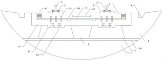
FIG. 1 is a schematic structural view of a subway rail of a rubber floating plate type polyurethane curing track bed according to the present invention;
FIG. 2 is a cross-sectional view of a rubber floating slab polyurethane cured track bed subway rail of the present invention;
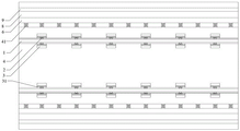
FIG. 3 is a schematic plan view of a subway rail of a rubber floating slab polyurethane curing track bed according to the present invention.
In the figure: 1. a steel rail; 2. a rail fastener; 3. a rail bearing platform; 31. a steel rail pressure-relieving pad; 4. a floating plate; 41. a buffer spring; 42. a buffer filler plate; 43. limiting the reinforcing steel bars; 44. a circular arc bump; 5. a rubber vibration damping pad; 6. a U-shaped groove; 61. a shear tooth groove; 62. shearing reinforcing steel bars; 7. polyurethane curing the ballast bed; 8. a ballast groove; 9. a drainage ditch; 10. an elastic cushion layer; 11. and (4) an inverted arch filling layer.
Detailed Description
The technical solution of the present invention will be clearly and completely described below with reference to the embodiments and the accompanying drawings. It should be apparent that the described embodiments are only some embodiments of the present invention, and not all embodiments. All other embodiments, which can be derived by a person skilled in the art from the embodiments given herein without making any creative effort, shall fall within the protection scope of the present invention. The specific embodiment is as follows:
a rubber floating plate type polyurethane curing track bed subway track structure is shown in figures 1, 2 and 3 and comprises a railway ballast groove 8 arranged along the direction of a line and a track structure in the railway ballast groove 8. The track structure mainly comprises a polyurethane curing track bed 7, a U-shaped groove 6 and a floating plate 4 from bottom to top. Polyurethane solidification track bed 7 is tiled in U type groove 6 bottom both sides, U type groove 6 bottom both sides are through setting up shear force tooth's socket 61 and shear force reinforcing bar 62 and polyurethane solidification track bed 7 concreties in fixing support department, floating plate 4 is located inside U type groove 6, be equipped with rubber damping pad 5 and buffer spring 41 between floating plate 4 and the U type groove 6, floating plate 4 and rubber damping pad 5 are through setting up spacing reinforcing bar 43 and circular arc lug 44 and U type groove 6 fixed connection, floating plate 4 inboard still is equipped with buffering infill panel 42 along the line direction.
The rubber floating plate type polyurethane curing track bed subway track structure is characterized in that the floating plates are of a prestressed reinforced concrete structure, a plurality of pairs of rail bearing platforms 3 are arranged on each floating plate 4, the upper parts of the rail bearing platforms 3 fix steel rails 1 through track fasteners 2, a layer of steel rail slow-pressing pad 31 is arranged between the rail bearing platforms 3 and the steel rails 1, when a locomotive passes through the steel rails 1, the impact load easily causes the breakage of the rail bearing platforms 3, and the steel rail slow-pressing pad 31 plays a first layer of buffering effect. The floating plate 4 is also provided with a buffer spring 41 and a buffer filling plate 42, any buffer spring 41 is positioned between the floating plate 4 and the side wall of the U-shaped groove 6, one end of the buffer spring 41 is fixedly connected with the floating plate 4, the other end of the buffer spring is fixedly connected with the side wall of the U-shaped groove 6, the buffer spring 41 is composed of a metal spiral spring and vulcanized rubber wrapped outside the metal spiral spring, and the buffer spring has very high load capacity, can disperse the impact force of a locomotive passing the floating plate 4 and limit the transverse displacement of the floating plate 4, and plays a role in protecting the second layer; the buffering filling plate 42 is positioned inside the floating plate 4 and fixedly connected with the floating plate 4, and the buffering filling plate 42 adopts rubber as a filling material, so that the impact force borne by the floating plate 4 can be dispersed, and the phenomenon that cracks appear on the solid floating plate 4 is effectively avoided.
This embodiment rubber floating plate formula polyurethane solidification railway roadbed subway track structure, 4 bottom both sides of floating plate are provided with spacing reinforcing bar 43 and circular arc lug 44 along the line direction, are equipped with one deck rubber damping pad 5 between floating plate 4 and the U type groove 6. Wherein, the rubber damping pad 5 can linearly support the upper floating plate 4, thereby reducing the integral natural frequency of the structure and having obvious damping effect. In addition, each limiting steel bar 43 and each circular arc bump 44 extend into the U-shaped groove 6, the floating plate 4, the rubber damping pad 5 and the U-shaped groove 6 are fixedly connected to form a composite structure, longitudinal force generated by the track structure is transmitted to the U-shaped groove 6, and longitudinal and transverse displacement of the floating plate 4 and the U-shaped groove 6 is limited.
This embodiment rubber floating plate formula polyurethane curing railway roadbed subway track structure, U type groove 6 is adopted from closely knit concrete to fill, can effectively bear vertical power and vertical horizontal power that the floating slab 4 transmitted, reaches the effect that disperses the train load, and 6 top both sides in U type groove and bottom middle zone are provided with railway ballast groove 8 along the line direction, and railway ballast groove 8 top both sides are equipped with escape canal 9. The two sides of the bottom of the U-shaped groove 6 are provided with shear tooth grooves 61 and shear steel bars 62 which are arranged at intervals along the line direction, the shear tooth grooves 61 can effectively control the telescopic deformation of the U-shaped groove 6, and meanwhile, the longitudinal and transverse displacements of the U-shaped groove 6 and the polyurethane curing track bed 7 are limited, and the shear steel bars 62 are combined with self-compaction concrete to solidify the U-shaped groove 6 and the polyurethane curing track bed 7 at a fixed support to form a high-level vibration damping track system.
In the subway track structure with the rubber floating plate type polyurethane curing track bed, the polyurethane curing track bed 7 is a basic structure formed by curing a high-molecular composite material, so that the stability of the track bed can be effectively enhanced, the accumulated deformation of the track bed can be slowed down, the huge load and impact generated when a train passes through a tunnel can be reduced, and the subway track structure with the rubber floating plate type polyurethane curing track bed has better vibration damping performance; the railway ballast groove 8 is formed by filling C35 mixed concrete, and the railway ballast groove 8 and the polyurethane solidified track bed 7 bear the load transmitted by the upper structure together. The elastic cushion layer 10 is arranged on the lower portions of the polyurethane curing ballast bed 7 and the ballast groove 8, so that impact of track structure load on a foundation can be effectively buffered, and the overall service life of the foundation is prolonged. An inverted arch filling layer 11 is laid below the elastic cushion layer 10, the inverted arch filling layer 11 is made of a self-repairing concrete material, and when the inner structure of the filling layer cracks due to large deformation, the repairing agent in the filling layer flows out to automatically bond.
It will be evident to those skilled in the art that the utility model is not limited to the details of the foregoing illustrative embodiments, and that the present invention may be embodied in other specific forms without departing from the spirit or essential attributes thereof. The present embodiments are therefore to be considered in all respects as illustrative and not restrictive, the scope of the utility model being indicated by the appended claims rather than by the foregoing description, and all changes which come within the meaning and range of equivalency of the claims are therefore intended to be embraced therein. Any reference sign in a claim should not be construed as limiting the claim concerned.
Furthermore, it should be understood that although the present description refers to embodiments, not every embodiment may contain only a single embodiment, and such description is for clarity only, and those skilled in the art should integrate the description, and the embodiments may be combined as appropriate to form other embodiments understood by those skilled in the art.