CN114715989B - Sponge City Sewage Treatment Recycling System - Google Patents
Sponge City Sewage Treatment Recycling System Download PDFInfo
- Publication number
- CN114715989B CN114715989B CN202210339141.0A CN202210339141A CN114715989B CN 114715989 B CN114715989 B CN 114715989B CN 202210339141 A CN202210339141 A CN 202210339141A CN 114715989 B CN114715989 B CN 114715989B
- Authority
- CN
- China
- Prior art keywords
- sewage
- pipe
- chamber
- vacuum chamber
- pipes
- Prior art date
- Legal status (The legal status is an assumption and is not a legal conclusion. Google has not performed a legal analysis and makes no representation as to the accuracy of the status listed.)
- Active
Links
- 239000010865 sewage Substances 0.000 title claims abstract description 154
- 238000004064 recycling Methods 0.000 title claims description 20
- XLYOFNOQVPJJNP-UHFFFAOYSA-N water Substances O XLYOFNOQVPJJNP-UHFFFAOYSA-N 0.000 claims abstract description 60
- 239000010802 sludge Substances 0.000 claims abstract description 35
- 238000005352 clarification Methods 0.000 claims abstract description 19
- 238000003756 stirring Methods 0.000 claims abstract description 16
- 239000007921 spray Substances 0.000 claims description 15
- 239000002351 wastewater Substances 0.000 claims description 2
- 238000005086 pumping Methods 0.000 claims 1
- 239000000725 suspension Substances 0.000 abstract description 28
- 238000004065 wastewater treatment Methods 0.000 abstract description 2
- 239000008394 flocculating agent Substances 0.000 abstract 1
- 238000011069 regeneration method Methods 0.000 abstract 1
- 238000005507 spraying Methods 0.000 abstract 1
- 239000007788 liquid Substances 0.000 description 30
- 239000000203 mixture Substances 0.000 description 16
- 239000006185 dispersion Substances 0.000 description 7
- 239000012535 impurity Substances 0.000 description 3
- 230000006698 induction Effects 0.000 description 3
- 238000007789 sealing Methods 0.000 description 3
- 230000009286 beneficial effect Effects 0.000 description 1
- 238000010586 diagram Methods 0.000 description 1
- 230000000694 effects Effects 0.000 description 1
- 238000005189 flocculation Methods 0.000 description 1
- 230000016615 flocculation Effects 0.000 description 1
- 239000003621 irrigation water Substances 0.000 description 1
- 238000004519 manufacturing process Methods 0.000 description 1
- 238000000034 method Methods 0.000 description 1
- 238000012986 modification Methods 0.000 description 1
- 230000004048 modification Effects 0.000 description 1
- 239000002245 particle Substances 0.000 description 1
- 238000000746 purification Methods 0.000 description 1
- 238000004062 sedimentation Methods 0.000 description 1
- 239000008247 solid mixture Substances 0.000 description 1
- 239000000126 substance Substances 0.000 description 1
Images

Classifications
-
- C—CHEMISTRY; METALLURGY
- C02—TREATMENT OF WATER, WASTE WATER, SEWAGE, OR SLUDGE
- C02F—TREATMENT OF WATER, WASTE WATER, SEWAGE, OR SLUDGE
- C02F1/00—Treatment of water, waste water, or sewage
- C02F1/52—Treatment of water, waste water, or sewage by flocculation or precipitation of suspended impurities
- C02F1/5209—Regulation methods for flocculation or precipitation
-
- Y—GENERAL TAGGING OF NEW TECHNOLOGICAL DEVELOPMENTS; GENERAL TAGGING OF CROSS-SECTIONAL TECHNOLOGIES SPANNING OVER SEVERAL SECTIONS OF THE IPC; TECHNICAL SUBJECTS COVERED BY FORMER USPC CROSS-REFERENCE ART COLLECTIONS [XRACs] AND DIGESTS
- Y02—TECHNOLOGIES OR APPLICATIONS FOR MITIGATION OR ADAPTATION AGAINST CLIMATE CHANGE
- Y02W—CLIMATE CHANGE MITIGATION TECHNOLOGIES RELATED TO WASTEWATER TREATMENT OR WASTE MANAGEMENT
- Y02W10/00—Technologies for wastewater treatment
- Y02W10/30—Wastewater or sewage treatment systems using renewable energies
- Y02W10/37—Wastewater or sewage treatment systems using renewable energies using solar energy
Landscapes
- Life Sciences & Earth Sciences (AREA)
- Hydrology & Water Resources (AREA)
- Engineering & Computer Science (AREA)
- Environmental & Geological Engineering (AREA)
- Water Supply & Treatment (AREA)
- Chemical & Material Sciences (AREA)
- Organic Chemistry (AREA)
- Treatment Of Sludge (AREA)
Abstract
Description
技术领域technical field
本发明涉及废水处理领域,具体涉及海绵城市污水处理后再生利用系统。The invention relates to the field of waste water treatment, in particular to a recycling system for sponge city sewage after treatment.
背景技术Background technique
为使污水达到排放标准或再次使用的水质要求,需要对污水进行净化处理,其中沉淀是常规净水处理工艺中的重要环节之一,利用悬浮层中的泥渣对原水中悬浮颗粒的接触絮凝作用来去除原水中悬浮杂质,具有占地面积小、处理效果好、生产效率高、布水较均匀以及节省药剂等特点。现有技术中,使悬浮层有规律的上下运动,将泥水进行分离,但存在悬浮层的固液混合物排出效率不高,排出的清水不干净的情况。In order to make the sewage meet the discharge standard or the water quality requirements for reuse, it is necessary to purify the sewage, among which sedimentation is one of the important links in the conventional water purification process. The contact flocculation of the suspended particles in the raw water by the sludge in the suspension layer is used It is used to remove suspended impurities in raw water, and has the characteristics of small footprint, good treatment effect, high production efficiency, uniform water distribution and saving chemicals. In the prior art, the suspension layer is moved up and down regularly to separate the muddy water, but the discharge efficiency of the solid-liquid mixture in the suspension layer is not high, and the discharged clear water is not clean.
发明内容Contents of the invention
发明人发现,现有技术中,悬浮层和清水层的排出位置比较接近,导致悬浮层上下移动时与清水混合,使得排出的固液混合物中杂质含量不高且清水中易混合杂质。The inventor found that in the prior art, the discharge positions of the suspension layer and the clear water layer are relatively close, causing the suspension layer to mix with the clean water when moving up and down, so that the impurity content in the discharged solid-liquid mixture is not high and the clean water is easy to mix impurities.
本发明提供海绵城市污水处理后再生利用系统,以解决现有技术中固液混合物排出效率不高且排出清水不干净的问题。The invention provides a sponge city sewage treatment recycling system to solve the problems in the prior art that the discharge efficiency of the solid-liquid mixture is not high and the discharged clean water is not clean.
本发明的海绵城市污水处理后再生利用系统采用如下技术方案:The sponge city sewage treatment post-recycling system of the present invention adopts the following technical scheme:
海绵城市污水处理后再生利用系统包括搅拌室、真空室、澄清池,搅拌室将污水和絮凝剂混合后持续送至真空室,真空室上方设置有真空泵和排气阀,真空泵用于对真空室的水面上方的空腔抽取真空,排气阀在真空泵开启状态下间歇开启和关闭;澄清池底部设置有多个污水管,每个污水管均为环形,且每个污水管的一端与真空室底部连通,另一端封闭;每个污水管上侧均设置有多个均匀分布的喷水口;多个污水管从内向外依次套接,且多个污水管的直径从内向外依次增大;多个污水管的一侧的间距小于另一侧的间距,且污水管间距较小的部分上方为密集区,间距较大的部分上方为分散区;澄清池内还设置有污泥收集池,污泥收集池侧壁开设有进污口,且进污口朝向密集区;澄清池侧壁且分散区的上方设置有出水管,出水管的高度高于进污口。Sponge city sewage recycling system includes mixing chamber, vacuum chamber and clarification tank. The stirring chamber mixes the sewage and flocculant and sends it to the vacuum chamber continuously. A vacuum pump and exhaust valve are installed above the vacuum chamber. The vacuum pump is used to clean the vacuum chamber. The cavity above the water surface draws vacuum, and the exhaust valve opens and closes intermittently when the vacuum pump is turned on; there are multiple sewage pipes at the bottom of the clarifier tank, each sewage pipe is ring-shaped, and one end of each sewage pipe is connected to the vacuum chamber The bottom is connected, and the other end is closed; the upper side of each sewage pipe is provided with a plurality of evenly distributed water spray ports; multiple sewage pipes are sequentially socketed from the inside to the outside, and the diameters of the multiple sewage pipes are sequentially increased from the inside to the outside; The distance between one side of multiple sewage pipes is smaller than that of the other side, and the part above the part with small distance between sewage pipes is a dense area, and the part above the part with large distance is a scattered area; A sewage inlet is opened on the side wall of the mud collection tank, and the sewage inlet faces the dense area; a water outlet pipe is arranged on the side wall of the clarification tank and above the dispersed area, and the height of the water outlet pipe is higher than the sewage inlet.
进一步地,污水管的与真空室底部连通的一端为首端,污水管的封闭的一端为末端;喷水口倾设置,喷水口使污水管内的污水从下往上且从污水管的首端向污水管的末端方向喷出。Further, the end of the sewage pipe connected to the bottom of the vacuum chamber is the head end, and the closed end of the sewage pipe is the end; the water spout is arranged at an angle, and the water spout makes the sewage in the sewage pipe flow from bottom to top and from the head end of the sewage pipe Spray toward the end of the sewage pipe.
进一步地,多个污水管的首端的间距和多个污水管的末端的间距均小于多个污水管的中部的间距,使得多个污水管的首端和末端处上方为密集区,多个污水管的中部上方为分散区。Further, the distance between the head ends of the plurality of sewage pipes and the distance between the ends of the plurality of sewage pipes are smaller than the distance between the middle parts of the plurality of sewage pipes, so that the upper ends of the plurality of sewage pipes and the ends are dense areas, and the plurality of sewage pipes Above the middle of the tube is the dispersion zone.
进一步地,搅拌室内设置有扇叶,扇叶转动安装于搅拌室内。Further, fan blades are arranged in the mixing chamber, and the fan blades are rotatably installed in the mixing chamber.
进一步地,海绵城市污水处理后再生利用系统还包括缓冲室,缓冲室位于搅拌室和真空室之间,且搅拌室内的污水水位达到第一预设高度后溢出至缓冲室;缓冲室底部设置有进水管,缓冲室内的污水通过进水管进入真空室。Further, the sponge city sewage treatment recycling system also includes a buffer chamber, the buffer chamber is located between the stirring chamber and the vacuum chamber, and the sewage water level in the stirring chamber overflows into the buffer chamber after reaching the first preset height; the bottom of the buffer chamber is provided with Water inlet pipe, the sewage in the buffer chamber enters the vacuum chamber through the water inlet pipe.
进一步地,污泥收集池有两个,分别位于污水管密集区的两侧,且两个污泥收集池上的进污口高度相等,均朝向密集区。Further, there are two sludge collection tanks, which are respectively located on both sides of the dense area of sewage pipes, and the sewage inlets on the two sludge collection tanks are of equal height, and both face the dense area.
进一步地,污泥收集池内设置有抽污管,抽污管在污泥收集池内污泥量积累至预设值时将污泥抽出。Further, a sewage suction pipe is provided in the sludge collection tank, and the sewage suction pipe will pump out the sludge when the amount of sludge in the sludge collection tank has accumulated to a preset value.
本发明的有益效果是:本发明的海绵城市污水处理后再生利用系统通过多个污水管的不均匀分布,使得澄清池内悬浮层的分布不均匀,且密集区的悬浮层高度大于分散区的悬浮层高度;并将污泥收集池的进污口朝向密集区,有利于悬浮层的泥水进入污泥收集池,且清水层的出水管设置于分散区上方,使得清水从悬浮层含量较少的分散区上方排出,避免排出的清水不干净。The beneficial effects of the present invention are: the uneven distribution of multiple sewage pipes in the sponge city sewage treatment recycling system of the present invention makes the distribution of the suspended layer in the clarifier uneven, and the height of the suspended layer in the dense area is greater than that in the dispersed area. The height of the layer; and the sewage inlet of the sludge collection tank is facing the dense area, which is conducive to the muddy water in the suspension layer entering the sludge collection tank, and the outlet pipe of the clear water layer is set above the dispersion area, so that the clean water can flow from the suspension layer with less content. Discharge above the dispersion area to avoid dirty water discharge.
进一步地,喷水口倾设置,使得污水管内的污水从下往上且从污水管的首端向污水管的末端方向喷出,促使悬浮层从分散区向密集区移动,进而使分散区悬浮层的固液混合物排出。Further, the water spray nozzle is set so that the sewage in the sewage pipe is sprayed from bottom to top and from the head end of the sewage pipe to the end of the sewage pipe, so that the suspended layer moves from the dispersed area to the dense area, and then the dispersed area is suspended. The solid-liquid mixture of the layer is discharged.
附图说明Description of drawings
为了更清楚地说明本发明实施例或现有技术中的技术方案,下面将对实施例或现有技术描述中所需要使用的附图作简单地介绍,显而易见地,下面描述中的附图仅仅是本发明的一些实施例,对于本领域普通技术人员来讲,在不付出创造性劳动性的前提下,还可以根据这些附图获得其他的附图。In order to more clearly illustrate the technical solutions in the embodiments of the present invention or the prior art, the following will briefly introduce the drawings that need to be used in the description of the embodiments or the prior art. Obviously, the accompanying drawings in the following description are only These are some embodiments of the present invention. For those skilled in the art, other drawings can also be obtained according to these drawings without any creative effort.
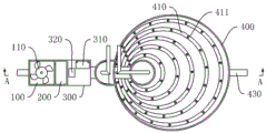
图1为本发明的海绵城市污水处理后再生利用系统的实施例整体结构俯视图;Fig. 1 is the top view of the overall structure of the embodiment of the sponge city sewage treatment recycling system of the present invention;
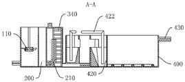
图2为图1的A-A向剖视图;Fig. 2 is the A-A direction sectional view of Fig. 1;
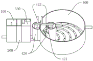
图3为本发明的海绵城市污水处理后再生利用系统的实施例整体结构示意图;3 is a schematic diagram of the overall structure of an embodiment of the sponge city sewage treatment recycling system of the present invention;
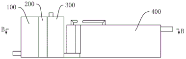
图4为本发明的海绵城市污水处理后再生利用系统的实施例整体结构正视图;Figure 4 is a front view of the overall structure of an embodiment of the sponge city sewage treatment recycling system of the present invention;
图5为图4的B-B向剖视图;Fig. 5 is the B-B direction sectional view of Fig. 4;
图中:100、搅拌室;110、扇叶;200、缓冲室;210、进水管;300、真空室;310、真空泵;320、排气阀;330、密封盖;340、梯子;400、澄清池;410、污水管;411、喷水口;420、污泥收集池;421、进污口;422、抽污管;430、出水管。In the figure: 100, mixing chamber; 110, fan blade; 200, buffer chamber; 210, water inlet pipe; 300, vacuum chamber; 310, vacuum pump; 320, exhaust valve; 330, sealing cover; 340, ladder; 400, clarification Pool; 410, sewage pipe; 411, water spout; 420, sludge collection tank; 421, sewage inlet; 422, sewage pipe; 430, outlet pipe.
具体实施方式Detailed ways
下面将结合本发明实施例中的附图,对本发明实施例中的技术方案进行清楚、完整地描述,显然,所描述的实施例仅仅是本发明一部分实施例,而不是全部的实施例。基于本发明中的实施例,本领域普通技术人员在没有做出创造性劳动前提下所获得的所有其他实施例,都属于本发明保护的范围。The following will clearly and completely describe the technical solutions in the embodiments of the present invention with reference to the accompanying drawings in the embodiments of the present invention. Obviously, the described embodiments are only some, not all, embodiments of the present invention. Based on the embodiments of the present invention, all other embodiments obtained by persons of ordinary skill in the art without making creative efforts belong to the protection scope of the present invention.
本发明的海绵城市污水处理后再生利用系统的实施例,如图1至图5所示,包括搅拌室100、真空室300、澄清池400,The embodiment of the recycling system after sponge city sewage treatment of the present invention, as shown in Figure 1 to Figure 5, comprises a
污水持续进入搅拌室100并在搅拌室100内与絮凝剂混合,搅拌室100将污水和絮凝剂混合后持续送至真空室300,The sewage continuously enters the
真空室300上端设置有密封盖330,密封盖330上安装有真空泵310和排气阀320,真空泵310用于对真空室300的液面上方的空腔抽取真空,排气阀320在真空泵310开启状态下间歇开启和关闭;且真空室300内设置有可进入底部的梯子340。The upper end of the
澄清池400底部设置有多个污水管410,每个污水管410均为环形,且每个污水管410的一端与真空室300底部连通,另一端封闭;每个污水管410上侧均设置有多个均匀分布的喷水口411;真空室300内的污水通过污水管410上的喷水口411进入澄清池400,并在澄清池400内分成悬浮层和清水层,其中,清水层位于悬浮层上方;多个污水管410从内向外依次套接,且多个污水管410的直径从内向外依次增大;多个污水管410的一侧的间距小于另一侧的间距,且污水管410间距较小的部分上方为密集区,间距较大的部分上方为分散区;由于喷水口411在污水管410上均匀分布,使得密集区的喷水口411的分布密度大于分散区喷水口411的分布密度,进而使密集区的悬浮层高度大于分散区的悬浮层高度;A plurality of
澄清池400内还设置有污泥收集池420,污泥收集池420侧壁开设有进污口421,且进污口421朝向密集区,悬浮层的固体混合物从进污口421进入污泥收集池420;澄清池400侧壁且分散区的上方设置有出水管430,出水管430的高度高于进污口421.清水层的水流从出水管430排出。A
澄清池400内液面高度与真空室300内液面高度相等时,真空泵310开启将真空室300内液面上方的空腔抽至真空,同时排气阀320处于关闭状态,进入真空室300内的污水不再向澄清池400流动,导致真空室300内液面升高,至真空室300内液面升高第二预设高度,排气阀320打开,真空室300内的污水进入澄清池400使得澄清池400内液面升高,澄清池400内悬浮层的固液混合物液面升高并从进污口421溢入污泥收集池420,上层的清水从出水管430排出;真空泵310保持开启状态,通过排气阀320的开启和关闭,使得澄清池400内液面间歇上升,进而使澄清池400内悬浮层的固液混合物间歇排出至污泥收集池420;且由于密集区的悬浮层高度大于分散区的悬浮层高度,进污口421朝向密集区更容易使悬浮层的固液混合物排出。When the liquid level in the
在本实施例中,污水管410的与真空室300底部连通的一端为首端,污水管410的封闭的一端为末端;喷水口411倾设置,喷水口411使污水管410内的污水从下往上且从污水管410的首端向污水管410的末端方向喷出,促使悬浮层从分散区上方向密集区上方移动,进而使分散区上方悬浮层的固液混合物排出。In this embodiment, the end of the
在本实施例中,多个污水管410的首端的间距和多个污水管410的末端的间距均小于多个污水管410的中部的间距,使得多个污水管410的首端和末端处的上方为密集区,多个污水管410的中部的上方为分散区。In this embodiment, the distance between the head ends of the
在本实施例中,搅拌室100内设置有扇叶110和电机,扇叶110安装于搅拌室100内并在电机的驱动下转动,以加速污水和絮凝剂的混合。In this embodiment, the
在本实施例中,海绵城市污水处理后再生利用系统还包括缓冲室200,缓冲室200位于搅拌室100和真空室300之间,且搅拌室100内的污水水位达到第一预设高度后溢出至缓冲室200;缓冲室200底部设置有进水管210,缓冲室200内的污水通过进水管210进入真空室300,缓冲室200为污水和絮凝剂的混合提供缓冲空间,从而使污水和絮凝剂充分混合。In this embodiment, the sponge city wastewater recycling system further includes a
在本实施例中,污泥收集池420有两个,分别位于污水管410密集区的两侧,且两个污泥收集池420上的进污口421高度相等,均朝向密集区,以使进入密集区的悬浮层的固液混合物从密集区的两侧均能排出。In this embodiment, there are two
在本实施例中,污泥收集池420内设置有抽污管422,抽污管422在污泥收集池420内污泥量积累至预设值时将污泥抽出,具体地,抽污管422可与抽吸泵连接,且污泥收集池420内预设高度处设置有感应装置,且感应装置与抽吸泵电连接,污泥收集池420内固液混合物达到预设值时,感应装置触发抽吸泵启动,抽吸泵通过抽污管422将污泥收集池420内的固液混合物抽出。In this embodiment, a
本发明的海绵城市污水处理后再生利用系统在使用时,污水持续进入搅拌室100且搅拌室100将污水和絮凝剂搅拌混合,搅拌室100内污水水位达到第一预设高度后溢出至缓冲室200,缓冲室200内的污水通过进水管210进入真空室300,真空室300内的污水通过污水管410上的喷水口411进入澄清池400,并在澄清池400内分成悬浮层和清水层,且清水层位于悬浮层上方。至澄清池400内液面高度与真空室300内液面高度相等时,真空泵310开启将真空室300内液面上方的空腔抽至真空,同时排气阀320处于关闭状态,进入真空室300内的污水不再向澄清池400流动,导致真空室300内液面升高,至真空室300内液面升高第二预设高度,排气阀320打开,真空室300内的污水进入澄清池400使得澄清池400内液面升高,澄清池400内悬浮层的固液混合物液面升高并从进污口421溢入污泥收集池420,上层的清水从出水管430排出后经处理可作为城市灌溉用水使用;真空泵310保持开启状态,通过排气阀320的开启和关闭,使得澄清池400内液面间歇上升,进而使澄清池400内悬浮层的固液混合物间歇排出至污泥收集池420;且由于密集区的悬浮层高度大于分散区的悬浮层高度,进污口421朝向密集区更容易使悬浮层的固液混合物排出。同时,由于喷水口411倾设置,喷水口411使污水管410内的污水从下往上且从污水管410的首端向污水管410的末端方向喷出,促使悬浮层从分散区向密集区上方移动,进而促使分散区悬浮层的固液混合物排出。When the sponge city sewage treatment recycling system of the present invention is in use, the sewage continuously enters the
以上所述仅为本发明的较佳实施例而已,并不用以限制本发明,凡在本发明的精神和原则之内,所作的任何修改、等同替换、改进等,均应包含在本发明的保护范围之内。The above descriptions are only preferred embodiments of the present invention, and are not intended to limit the present invention. Any modifications, equivalent replacements, improvements, etc. made within the spirit and principles of the present invention shall be included in the scope of the present invention. within the scope of protection.
Claims (7)
Priority Applications (1)
| Application Number | Priority Date | Filing Date | Title |
|---|---|---|---|
| CN202210339141.0A CN114715989B (en) | 2022-04-01 | 2022-04-01 | Sponge City Sewage Treatment Recycling System |
Applications Claiming Priority (1)
| Application Number | Priority Date | Filing Date | Title |
|---|---|---|---|
| CN202210339141.0A CN114715989B (en) | 2022-04-01 | 2022-04-01 | Sponge City Sewage Treatment Recycling System |
Publications (2)
| Publication Number | Publication Date |
|---|---|
| CN114715989A CN114715989A (en) | 2022-07-08 |
| CN114715989B true CN114715989B (en) | 2023-01-31 |
Family
ID=82241462
Family Applications (1)
| Application Number | Title | Priority Date | Filing Date |
|---|---|---|---|
| CN202210339141.0A Active CN114715989B (en) | 2022-04-01 | 2022-04-01 | Sponge City Sewage Treatment Recycling System |
Country Status (1)
| Country | Link |
|---|---|
| CN (1) | CN114715989B (en) |
Citations (11)
| Publication number | Priority date | Publication date | Assignee | Title |
|---|---|---|---|---|
| SU601025A1 (en) * | 1975-07-18 | 1978-04-05 | Государственный Проектный Институт "Укрводоканалпроект" | Water distributor |
| JPH1128312A (en) * | 1997-05-16 | 1999-02-02 | Hitachi Plant Eng & Constr Co Ltd | Coagulation sedimentation equipment |
| CN102179076A (en) * | 2011-04-04 | 2011-09-14 | 哈尔滨辰能工大环保科技股份有限公司 | Uniform surface water collecting apparatus |
| CN202208653U (en) * | 2011-09-04 | 2012-05-02 | 广东汇众环境科技股份有限公司 | Air float clarifying treatment equipment |
| CN202962001U (en) * | 2012-11-21 | 2013-06-05 | 常州江南环境工程有限公司 | Water distributor for defecator |
| CN203408504U (en) * | 2013-07-16 | 2014-01-29 | 重庆泰克环保工程设备有限公司 | Vertical sedimentation basin |
| CN203999108U (en) * | 2014-07-28 | 2014-12-10 | 武汉芳笛环保股份有限公司 | A kind of IBR central authorities' collective and distributive type water distribution collection mud aerator island |
| CN106277311A (en) * | 2016-10-21 | 2017-01-04 | 大连碧蓝节能环保科技有限公司 | Water conservancy diversion impeller up flow anaerobic sludge blanket reactor |
| CN107265585A (en) * | 2017-06-28 | 2017-10-20 | 王娜 | A kind of depositing reservoir pulse generating unit and method |
| JP2019150767A (en) * | 2018-03-02 | 2019-09-12 | 株式会社東芝 | Inflow part unit and settling tank |
| CN209500914U (en) * | 2019-01-16 | 2019-10-18 | 安徽利和水务有限公司 | A kind of water jet mud scum cleaning plant for secondary settling tank |
-
2022
- 2022-04-01 CN CN202210339141.0A patent/CN114715989B/en active Active
Patent Citations (11)
| Publication number | Priority date | Publication date | Assignee | Title |
|---|---|---|---|---|
| SU601025A1 (en) * | 1975-07-18 | 1978-04-05 | Государственный Проектный Институт "Укрводоканалпроект" | Water distributor |
| JPH1128312A (en) * | 1997-05-16 | 1999-02-02 | Hitachi Plant Eng & Constr Co Ltd | Coagulation sedimentation equipment |
| CN102179076A (en) * | 2011-04-04 | 2011-09-14 | 哈尔滨辰能工大环保科技股份有限公司 | Uniform surface water collecting apparatus |
| CN202208653U (en) * | 2011-09-04 | 2012-05-02 | 广东汇众环境科技股份有限公司 | Air float clarifying treatment equipment |
| CN202962001U (en) * | 2012-11-21 | 2013-06-05 | 常州江南环境工程有限公司 | Water distributor for defecator |
| CN203408504U (en) * | 2013-07-16 | 2014-01-29 | 重庆泰克环保工程设备有限公司 | Vertical sedimentation basin |
| CN203999108U (en) * | 2014-07-28 | 2014-12-10 | 武汉芳笛环保股份有限公司 | A kind of IBR central authorities' collective and distributive type water distribution collection mud aerator island |
| CN106277311A (en) * | 2016-10-21 | 2017-01-04 | 大连碧蓝节能环保科技有限公司 | Water conservancy diversion impeller up flow anaerobic sludge blanket reactor |
| CN107265585A (en) * | 2017-06-28 | 2017-10-20 | 王娜 | A kind of depositing reservoir pulse generating unit and method |
| JP2019150767A (en) * | 2018-03-02 | 2019-09-12 | 株式会社東芝 | Inflow part unit and settling tank |
| CN209500914U (en) * | 2019-01-16 | 2019-10-18 | 安徽利和水务有限公司 | A kind of water jet mud scum cleaning plant for secondary settling tank |
Also Published As
| Publication number | Publication date |
|---|---|
| CN114715989A (en) | 2022-07-08 |
Similar Documents
| Publication | Publication Date | Title |
|---|---|---|
| CN108379885A (en) | A kind of detention tank and its combined-flow are from clear method | |
| CN107381700A (en) | A kind of multistage ozone air-float technique slag-draining device based on siphon principle | |
| CN114715989B (en) | Sponge City Sewage Treatment Recycling System | |
| CN211283968U (en) | Novel flocculation basin | |
| CN113521808A (en) | New process for treating tail water of tap water | |
| CN112142151A (en) | Shallow layer air supporting device on water | |
| CN208517032U (en) | A kind of efficiently micro- sand sedimentation basin | |
| CN208869368U (en) | A kind of high-efficiency environment friendly sewage treatment sedimentation basin | |
| CN208975286U (en) | A kind of girt-water separation device in kitchen, kitchen waste processing | |
| CN217297496U (en) | Sewage sand removing device | |
| CN208065845U (en) | Combined-flow self-cleaning inclined tube or inclined-plate clarifying basin | |
| CN217972684U (en) | Membrane purification treatment device | |
| KR100753874B1 (en) | Agglomerator with scum discharge | |
| CN215161282U (en) | Sewage treatment device | |
| CN215102515U (en) | Pressure type ceramic tubular membrane hardness and silicon removal integrated system | |
| CN210973974U (en) | Cavitation air flotation machine for sewage treatment | |
| CN207072893U (en) | A kind of industrial wastewater processing unit | |
| CN220812147U (en) | Industrial sewage inclined tube precipitation device | |
| CN211676443U (en) | Clarification tank | |
| CN221166206U (en) | Sewage filters uses high-efficient sedimentation tank | |
| CN219701197U (en) | Sand discharge pipeline structure of cyclone sand setting tank | |
| CN212053165U (en) | An annular jet vacuum sewage suction truck | |
| CN221344170U (en) | Water circulation device of sedimentation tank | |
| CN216336781U (en) | Built-in mud reflux unit of sedimentation tank | |
| CN219630830U (en) | Efficient activated carbon micro-sand sedimentation tank |
Legal Events
| Date | Code | Title | Description |
|---|---|---|---|
| PB01 | Publication | ||
| PB01 | Publication | ||
| SE01 | Entry into force of request for substantive examination | ||
| SE01 | Entry into force of request for substantive examination | ||
| GR01 | Patent grant | ||
| GR01 | Patent grant |