CN114715989A - Sponge municipal sewage treatment post-regeneration utilization system - Google Patents
Sponge municipal sewage treatment post-regeneration utilization system Download PDFInfo
- Publication number
- CN114715989A CN114715989A CN202210339141.0A CN202210339141A CN114715989A CN 114715989 A CN114715989 A CN 114715989A CN 202210339141 A CN202210339141 A CN 202210339141A CN 114715989 A CN114715989 A CN 114715989A
- Authority
- CN
- China
- Prior art keywords
- sewage
- pipe
- chamber
- vacuum chamber
- pipes
- Prior art date
- Legal status (The legal status is an assumption and is not a legal conclusion. Google has not performed a legal analysis and makes no representation as to the accuracy of the status listed.)
- Granted
Links
Images
Classifications
-
- C—CHEMISTRY; METALLURGY
- C02—TREATMENT OF WATER, WASTE WATER, SEWAGE, OR SLUDGE
- C02F—TREATMENT OF WATER, WASTE WATER, SEWAGE, OR SLUDGE
- C02F1/00—Treatment of water, waste water, or sewage
- C02F1/52—Treatment of water, waste water, or sewage by flocculation or precipitation of suspended impurities
- C02F1/5209—Regulation methods for flocculation or precipitation
-
- Y—GENERAL TAGGING OF NEW TECHNOLOGICAL DEVELOPMENTS; GENERAL TAGGING OF CROSS-SECTIONAL TECHNOLOGIES SPANNING OVER SEVERAL SECTIONS OF THE IPC; TECHNICAL SUBJECTS COVERED BY FORMER USPC CROSS-REFERENCE ART COLLECTIONS [XRACs] AND DIGESTS
- Y02—TECHNOLOGIES OR APPLICATIONS FOR MITIGATION OR ADAPTATION AGAINST CLIMATE CHANGE
- Y02W—CLIMATE CHANGE MITIGATION TECHNOLOGIES RELATED TO WASTEWATER TREATMENT OR WASTE MANAGEMENT
- Y02W10/00—Technologies for wastewater treatment
- Y02W10/30—Wastewater or sewage treatment systems using renewable energies
- Y02W10/37—Wastewater or sewage treatment systems using renewable energies using solar energy
Landscapes
- Life Sciences & Earth Sciences (AREA)
- Hydrology & Water Resources (AREA)
- Engineering & Computer Science (AREA)
- Environmental & Geological Engineering (AREA)
- Water Supply & Treatment (AREA)
- Chemical & Material Sciences (AREA)
- Organic Chemistry (AREA)
- Treatment Of Sludge (AREA)
Abstract
The invention relates to the field of wastewater treatment, in particular to a sponge municipal sewage treatment and recycling system, which comprises a stirring chamber, a vacuum chamber and a clarification tank, wherein the stirring chamber is used for mixing sewage and a flocculating agent and then continuously sending the mixed sewage to the vacuum chamber, and a vacuum pump and an exhaust valve are arranged above the vacuum chamber; the bottom of the clarification tank is provided with a plurality of sewage pipes, each sewage pipe is annular, and each sewage pipe is communicated with the bottom of the vacuum chamber; the upper side of each sewage pipe is provided with a plurality of uniformly distributed water spraying ports; the upper parts of the sewage pipes which are unevenly distributed and have smaller intervals are dense areas, and the upper parts of the sewage pipes which have larger intervals are dispersive areas; causing the height of the suspension layer in the dense area to be greater than the height of the suspension layer in the dispersed area; and the sludge inlet of the sludge collection tank faces the dense area, so that muddy water on the suspended layer can enter the sludge collection tank, and the water outlet pipe of the clear water layer is arranged above the dispersed area, so that clear water is discharged from the upper part of the dispersed area with less content in the suspended layer, and the unclean clear water is avoided.
Description
Technical Field
The invention relates to the field of wastewater treatment, in particular to a sponge municipal sewage treatment and recycling system.
Background
In order to enable the sewage to reach the discharge standard or meet the water quality requirement of reuse, the sewage needs to be purified, wherein precipitation is one of important links in the conventional water purification treatment process, suspended impurities in raw water are removed by utilizing the contact flocculation effect of sludge in a suspended layer on suspended particles in the raw water, and the method has the characteristics of small floor area, good treatment effect, high production efficiency, uniform water distribution, medicament saving and the like. In the prior art, the suspension layer moves up and down regularly to separate mud and water, but the discharge efficiency of solid-liquid mixture in the suspension layer is not high, and the discharged clear water is not clean.
Disclosure of Invention
The inventor finds that in the prior art, the discharge positions of the suspension layer and the clear water layer are relatively close to each other, so that the suspension layer is mixed with the clear water when moving up and down, the impurity content in the discharged solid-liquid mixture is not high, and impurities are easy to mix in the clear water.
The invention provides a sponge municipal sewage treatment and recycling system, which aims to solve the problems that in the prior art, the discharge efficiency of solid-liquid mixtures is low and the discharged clear water is not clean.
The sponge municipal sewage treatment post-regeneration utilization system adopts the following technical scheme:
the recycling system for the treated sponge municipal sewage comprises a stirring chamber, a vacuum chamber and a clarification tank, wherein the stirring chamber continuously sends the sewage and a flocculating agent to the vacuum chamber after mixing the sewage and the flocculating agent, a vacuum pump and an exhaust valve are arranged above the vacuum chamber, the vacuum pump is used for pumping vacuum to a cavity above the water surface of the vacuum chamber, and the exhaust valve is intermittently opened and closed when the vacuum pump is opened; the bottom of the clarification tank is provided with a plurality of sewage pipes, each sewage pipe is annular, one end of each sewage pipe is communicated with the bottom of the vacuum chamber, and the other end of each sewage pipe is closed; the upper side of each sewage pipe is provided with a plurality of uniformly distributed water spraying ports; the sewage pipes are sequentially sleeved from inside to outside, and the diameters of the sewage pipes are sequentially increased from inside to outside; the space between one sides of the sewage pipes is smaller than that between the other sides of the sewage pipes, a dense area is arranged above the part with the smaller space between the sewage pipes, and a dispersed area is arranged above the part with the larger space between the sewage pipes; a sludge collecting tank is also arranged in the clarifying tank, a sewage inlet is formed in the side wall of the sludge collecting tank, and the sewage inlet faces to the dense area; and a water outlet pipe is arranged on the side wall of the clarification tank and above the dispersion area, and the height of the water outlet pipe is higher than that of the sewage inlet.
Furthermore, one end of the sewage pipe communicated with the bottom of the vacuum chamber is a head end, and the closed end of the sewage pipe is a tail end; the water spraying opening is arranged obliquely, and the water spraying opening enables sewage in the sewage pipe to be sprayed out from bottom to top and from the head end of the sewage pipe to the tail end direction of the sewage pipe.
Further, the distance between the head ends of the sewage pipes and the distance between the tail ends of the sewage pipes are smaller than the distance between the middle parts of the sewage pipes, so that dense areas are arranged above the head ends and the tail ends of the sewage pipes, and a dispersed area is arranged above the middle parts of the sewage pipes.
Furthermore, the stirring chamber is internally provided with fan blades which are rotatably arranged in the stirring chamber.
Furthermore, the sponge municipal sewage treatment and recycling system also comprises a buffer chamber, wherein the buffer chamber is positioned between the stirring chamber and the vacuum chamber, and the sewage level in the stirring chamber reaches a first preset height and then overflows to the buffer chamber; the bottom of the buffer chamber is provided with a water inlet pipe, and sewage in the buffer chamber enters the vacuum chamber through the water inlet pipe.
Furthermore, two sludge collecting tanks are respectively arranged at two sides of the sewage pipe dense area, and the heights of the sewage inlets on the two sludge collecting tanks are equal and all face the dense area.
Further, be provided with in the sludge collection pond and take out the dirty pipe, take out dirty pipe and take out mud when the sludge amount accumulation reaches the default in the sludge collection pond.
The invention has the beneficial effects that: the recycling system for the treated sponge municipal sewage ensures that the distribution of the suspension layer in the clarifying tank is uneven through the uneven distribution of the plurality of sewage pipes, and the height of the suspension layer in the dense area is greater than that of the suspension layer in the dispersed area; and the sludge inlet of the sludge collection tank faces the dense area, so that muddy water on the suspended layer can enter the sludge collection tank, and the water outlet pipe of the clear water layer is arranged above the dispersed area, so that clear water is discharged from the upper part of the dispersed area with less content in the suspended layer, and the unclean clear water is avoided.
Furthermore, the water spray nozzles are arranged in an inclined mode, so that sewage in the sewage pipe is sprayed out from bottom to top and from the head end of the sewage pipe to the tail end of the sewage pipe, the suspension layer is promoted to move from the dispersion area to the dense area, and then the solid-liquid mixture in the suspension layer in the dispersion area is discharged.
Drawings
In order to more clearly illustrate the embodiments of the present invention or the technical solutions in the prior art, the drawings used in the description of the embodiments or the prior art will be briefly described below, and it is obvious that the drawings in the following description are only some embodiments of the present invention, and for those skilled in the art, other drawings can be obtained according to these drawings without creative efforts.
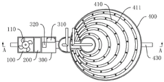
FIG. 1 is a top view of the overall structure of an embodiment of the sponge municipal sewage treatment and recycling system of the invention;
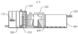
FIG. 2 is a sectional view taken along line A-A of FIG. 1;
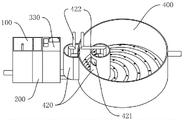
FIG. 3 is a schematic view of the overall structure of an embodiment of the sponge municipal sewage treatment and recycling system of the invention;
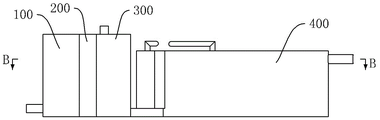
FIG. 4 is a front view of the overall structure of an embodiment of the sponge municipal sewage treatment and recycling system of the invention;
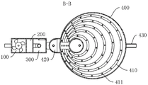
FIG. 5 is a sectional view taken along line B-B of FIG. 4;
in the figure: 100. a stirring chamber; 110. a fan blade; 200. a buffer chamber; 210. a water inlet pipe; 300. a vacuum chamber; 310. a vacuum pump; 320. an exhaust valve; 330. a sealing cover; 340. a ladder; 400. a clarification tank; 410. a sewage pipe; 411. a water jet; 420. a sludge collection tank; 421. a sewage inlet; 422. a sewage pumping pipe; 430. and (5) discharging a water pipe.
Detailed Description
The technical solutions in the embodiments of the present invention will be clearly and completely described below with reference to the drawings in the embodiments of the present invention, and it is obvious that the described embodiments are only a part of the embodiments of the present invention, and not all of the embodiments. All other embodiments, which can be derived by a person skilled in the art from the embodiments given herein without making any creative effort, shall fall within the protection scope of the present invention.
The embodiment of the sponge municipal sewage treatment and recycling system of the invention, as shown in figures 1 to 5, comprises a stirring chamber 100, a vacuum chamber 300 and a clarification tank 400,
the sewage continuously enters the stirring chamber 100 and is mixed with the flocculating agent in the stirring chamber 100, the stirring chamber 100 continuously sends the sewage and the flocculating agent to the vacuum chamber 300 after mixing,
the upper end of the vacuum chamber 300 is provided with a sealing cover 330, the sealing cover 330 is provided with a vacuum pump 310 and an exhaust valve 320, the vacuum pump 310 is used for pumping vacuum to the cavity above the liquid level of the vacuum chamber 300, and the exhaust valve 320 is intermittently opened and closed when the vacuum pump 310 is opened; and a ladder 340 is provided inside the vacuum chamber 300 to allow access to the bottom.
The bottom of the clarifier 400 is provided with a plurality of sewage pipes 410, each sewage pipe 410 is annular, one end of each sewage pipe 410 is communicated with the bottom of the vacuum chamber 300, and the other end is closed; a plurality of water spraying ports 411 which are uniformly distributed are arranged on the upper side of each sewage pipe 410; the sewage in the vacuum chamber 300 enters the clarification tank 400 through a water spray opening 411 on the sewage pipe 410 and is divided into a suspension layer and a clear water layer in the clarification tank 400, wherein the clear water layer is positioned above the suspension layer; the plurality of sewage pipes 410 are sequentially sleeved from inside to outside, and the diameters of the plurality of sewage pipes 410 are sequentially increased from inside to outside; the space between one side of the sewage pipes 410 is smaller than that between the other side, a dense area is arranged above the part with the smaller space between the sewage pipes 410, and a dispersed area is arranged above the part with the larger space; because the water spray ports 411 are uniformly distributed on the sewage pipe 410, the distribution density of the water spray ports 411 in the dense area is higher than that of the water spray ports 411 in the dispersed area, and further the height of the suspension layer in the dense area is higher than that of the suspension layer in the dispersed area;
a sludge collection tank 420 is further arranged in the clarification tank 400, a sludge inlet 421 is formed in the side wall of the sludge collection tank 420, the sludge inlet 421 faces the dense area, and the solid mixture in the suspension layer enters the sludge collection tank 420 from the sludge inlet 421; the side wall of the clarification tank 400 and above the dispersion area is provided with a water outlet pipe 430, the height of the water outlet pipe 430 is higher than the sewage inlet 421, and the water flow of the clean water layer is discharged from the water outlet pipe 430.
When the liquid level in the clarification tank 400 is equal to the liquid level in the vacuum chamber 300, the vacuum pump 310 is started to pump the cavity above the liquid level in the vacuum chamber 300 to vacuum, meanwhile, the exhaust valve 320 is in a closed state, the sewage entering the vacuum chamber 300 does not flow to the clarification tank 400 any more, so that the liquid level in the vacuum chamber 300 rises, the liquid level rises to the liquid level in the vacuum chamber 300 by a second preset height, the exhaust valve 320 is opened, the sewage entering the clarification tank 400 in the vacuum chamber 300 causes the liquid level in the clarification tank 400 to rise, the liquid level of the solid-liquid mixture in the suspension layer in the clarification tank 400 rises and overflows into the sludge collection tank 420 from the sewage inlet 421, and the upper clear water is discharged from the water outlet pipe 430; the vacuum pump 310 is kept in an open state, and the liquid level in the clarification tank 400 is intermittently raised through opening and closing of the exhaust valve 320, so that the solid-liquid mixture in the suspension layer in the clarification tank 400 is intermittently discharged to the sludge collection tank 420; and because the height of the suspension layer in the dense area is greater than that of the suspension layer in the dispersed area, the sewage inlet 421 faces the dense area, so that the solid-liquid mixture in the suspension layer is easier to discharge.
In this embodiment, one end of the sewage pipe 410 communicating with the bottom of the vacuum chamber 300 is a head end, and the closed end of the sewage pipe 410 is a tail end; the water spray opening 411 is arranged obliquely, and the water spray opening 411 enables sewage in the sewage pipe 410 to be sprayed out from bottom to top and from the head end of the sewage pipe 410 to the tail end direction of the sewage pipe 410, so that the suspension layer is promoted to move from the upper part of the dispersion area to the upper part of the dense area, and further the solid-liquid mixture in the suspension layer above the dispersion area is discharged.
In this embodiment, the distance between the head ends of the sewage pipes 410 and the distance between the tail ends of the sewage pipes 410 are smaller than the distance between the middle portions of the sewage pipes 410, so that the upper portions of the head ends and the tail ends of the sewage pipes 410 are dense areas, and the upper portions of the middle portions of the sewage pipes 410 are dispersion areas.
In the embodiment, a fan blade 110 and a motor are disposed in the stirring chamber 100, and the fan blade 110 is installed in the stirring chamber 100 and driven by the motor to rotate, so as to accelerate the mixing of the sewage and the flocculant.
In this embodiment, the sponge municipal sewage treatment and recycling system further comprises a buffer chamber 200, the buffer chamber 200 is located between the stirring chamber 100 and the vacuum chamber 300, and the sewage level in the stirring chamber 100 reaches a first preset height and then overflows to the buffer chamber 200; the bottom of the buffer chamber 200 is provided with a water inlet pipe 210, the sewage in the buffer chamber 200 enters the vacuum chamber 300 through the water inlet pipe 210, and the buffer chamber 200 provides a buffer space for the mixing of the sewage and the flocculating agent, so that the sewage and the flocculating agent are fully mixed.
In this embodiment, there are two sludge collecting tanks 420, which are respectively located at two sides of the dense area of the sewage pipe 410, and the height of the sewage inlets 421 on the two sludge collecting tanks 420 is equal and both face the dense area, so that the solid-liquid mixture entering the suspended layer of the dense area can be discharged from two sides of the dense area.
In this embodiment, be provided with in sludge collection pond 420 and take out dirty pipe 422, take out dirty pipe 422 and take out mud when the sludge amount accumulation reaches the default in sludge collection pond 420, specifically, take out dirty pipe 422 can be connected with the suction pump, and predetermine high department in the sludge collection pond 420 and be provided with induction system, and induction system is connected with the suction pump electricity, when solid-liquid mixture reaches the default in sludge collection pond 420, induction system triggers the suction pump and starts, the suction pump takes out the solid-liquid mixture in sludge collection pond 420 through taking out dirty pipe 422.
When the sponge municipal sewage treatment and recycling system is used, sewage continuously enters the stirring chamber 100, the stirring chamber 100 stirs and mixes the sewage and the flocculating agent, the sewage level in the stirring chamber 100 reaches a first preset height and then overflows to the buffer chamber 200, the sewage in the buffer chamber 200 enters the vacuum chamber 300 through the water inlet pipe 210, the sewage in the vacuum chamber 300 enters the clarification tank 400 through the water spray opening 411 on the sewage pipe 410, and is divided into a suspension layer and a clear water layer in the clarification tank 400, and the clear water layer is positioned above the suspension layer. When the liquid level in the clarification tank 400 is equal to the liquid level in the vacuum chamber 300, the vacuum pump 310 is started to pump the cavity above the liquid level in the vacuum chamber 300 to vacuum, the exhaust valve 320 is closed, the sewage entering the vacuum chamber 300 does not flow to the clarification tank 400 any more, so that the liquid level in the vacuum chamber 300 rises, the liquid level rises to the liquid level in the vacuum chamber 300 by a second preset height, the exhaust valve 320 is opened, the sewage entering the vacuum chamber 300 enters the clarification tank 400 to rise the liquid level in the clarification tank 400, the liquid level of a solid-liquid mixture in a suspension layer in the clarification tank 400 rises and overflows into the sludge collection tank 420 from the sewage inlet 421, and the upper clear water can be used as urban irrigation water after being discharged from the water outlet pipe 430 and treated; the vacuum pump 310 is kept in an open state, and the liquid level in the clarification tank 400 is intermittently raised through opening and closing of the exhaust valve 320, so that the solid-liquid mixture in the suspension layer in the clarification tank 400 is intermittently discharged to the sludge collection tank 420; and because the height of the suspension layer in the dense area is greater than that of the suspension layer in the dispersed area, the sewage inlet 421 faces the dense area, so that the solid-liquid mixture in the suspension layer is easier to discharge. Meanwhile, because the water spray opening 411 is arranged obliquely, the water spray opening 411 enables the sewage in the sewage pipe 410 to be sprayed out from bottom to top and from the head end of the sewage pipe 410 to the tail end direction of the sewage pipe 410, so that the suspension layer is enabled to move from the dispersion area to the upper part of the dense area, and further the solid-liquid mixture in the suspension layer in the dispersion area is enabled to be discharged.
The above description is only for the purpose of illustrating the preferred embodiments of the present invention and is not to be construed as limiting the invention, and any modifications, equivalents, improvements and the like that fall within the spirit and principle of the present invention are intended to be included therein.
Claims (7)
1. Sponge municipal sewage handles back regeneration system, its characterized in that: the sewage treatment device comprises a stirring chamber, a vacuum chamber and a clarification tank, wherein the stirring chamber continuously conveys sewage and a flocculating agent to the vacuum chamber after mixing the sewage and the flocculating agent, a vacuum pump and an exhaust valve are arranged above the vacuum chamber, the vacuum pump is used for pumping vacuum to a cavity above the water surface of the vacuum chamber, and the exhaust valve is intermittently opened and closed when the vacuum pump is opened; the bottom of the clarification tank is provided with a plurality of sewage pipes, each sewage pipe is annular, one end of each sewage pipe is communicated with the bottom of the vacuum chamber, and the other end of each sewage pipe is closed; the upper side of each sewage pipe is provided with a plurality of uniformly distributed water spraying ports; the sewage pipes are sequentially sleeved from inside to outside, and the diameters of the sewage pipes are sequentially increased from inside to outside; the space between one sides of the sewage pipes is smaller than that between the other sides of the sewage pipes, a dense area is arranged above the part with the smaller space between the sewage pipes, and a dispersed area is arranged above the part with the larger space between the sewage pipes; a sludge collecting tank is also arranged in the clarifying tank, a sewage inlet is formed in the side wall of the sludge collecting tank, and the sewage inlet faces to the dense area; and a water outlet pipe is arranged on the side wall of the clarification tank and above the dispersion area, and the height of the water outlet pipe is higher than that of the sewage inlet.
2. The sponge municipal sewage treatment and recycling system according to claim 1, wherein the sponge municipal sewage treatment and recycling system comprises: one end of the sewage pipe communicated with the bottom of the vacuum chamber is a head end, and the closed end of the sewage pipe is a tail end; the water spraying opening is arranged obliquely, and the water spraying opening enables sewage in the sewage pipe to be sprayed out from bottom to top and from the head end of the sewage pipe to the tail end direction of the sewage pipe.
3. The sponge municipal sewage treatment and recycling system according to claim 2, wherein the sponge municipal sewage treatment and recycling system comprises: the distance between the head ends of the sewage pipes and the distance between the tail ends of the sewage pipes are smaller than the distance between the middle parts of the sewage pipes, so that the upper parts of the head ends and the tail ends of the sewage pipes are compact areas, and the upper parts of the middle parts of the sewage pipes are dispersive areas.
4. The sponge municipal sewage treatment and recycling system according to claim 1, wherein the sponge municipal sewage treatment and recycling system comprises: the stirring chamber is internally provided with fan blades which are rotatably arranged in the stirring chamber.
5. The sponge municipal sewage treatment and recycling system according to claim 1, wherein the sponge municipal sewage treatment and recycling system comprises: the vacuum stirring device also comprises a buffer chamber, wherein the buffer chamber is positioned between the stirring chamber and the vacuum chamber, and the sewage level in the stirring chamber overflows to the buffer chamber after reaching a first preset height; the bottom of the buffer chamber is provided with a water inlet pipe, and sewage in the buffer chamber enters the vacuum chamber through the water inlet pipe.
6. The sponge municipal sewage treatment and recycling system according to claim 1, wherein the sponge municipal sewage treatment and recycling system comprises: the two sludge collecting tanks are respectively positioned at two sides of the sewage pipe dense area, and the height of the sewage inlets on the two sludge collecting tanks is equal and both face the dense area.
7. The sponge municipal sewage treatment post-regeneration utilization system according to claim 6, wherein: be provided with in the sludge collection pond and take out the dirty pipe, take out dirty pipe and take out mud when the sludge mass accumulation reaches the default in the sludge collection pond.
Priority Applications (1)
| Application Number | Priority Date | Filing Date | Title |
|---|---|---|---|
| CN202210339141.0A CN114715989B (en) | 2022-04-01 | 2022-04-01 | Sponge municipal sewage treatment post-regeneration utilization system |
Applications Claiming Priority (1)
| Application Number | Priority Date | Filing Date | Title |
|---|---|---|---|
| CN202210339141.0A CN114715989B (en) | 2022-04-01 | 2022-04-01 | Sponge municipal sewage treatment post-regeneration utilization system |
Publications (2)
| Publication Number | Publication Date |
|---|---|
| CN114715989A true CN114715989A (en) | 2022-07-08 |
| CN114715989B CN114715989B (en) | 2023-01-31 |
Family
ID=82241462
Family Applications (1)
| Application Number | Title | Priority Date | Filing Date |
|---|---|---|---|
| CN202210339141.0A Active CN114715989B (en) | 2022-04-01 | 2022-04-01 | Sponge municipal sewage treatment post-regeneration utilization system |
Country Status (1)
| Country | Link |
|---|---|
| CN (1) | CN114715989B (en) |
Citations (11)
| Publication number | Priority date | Publication date | Assignee | Title |
|---|---|---|---|---|
| SU601025A1 (en) * | 1975-07-18 | 1978-04-05 | Государственный Проектный Институт "Укрводоканалпроект" | Water distributor |
| JPH1128312A (en) * | 1997-05-16 | 1999-02-02 | Hitachi Plant Eng & Constr Co Ltd | Flocculator |
| CN102179076A (en) * | 2011-04-04 | 2011-09-14 | 哈尔滨辰能工大环保科技股份有限公司 | Uniform surface water collecting apparatus |
| CN202208653U (en) * | 2011-09-04 | 2012-05-02 | 广东汇众环境科技股份有限公司 | Air float clarifying treatment equipment |
| CN202962001U (en) * | 2012-11-21 | 2013-06-05 | 常州江南环境工程有限公司 | Water distributor for defecator |
| CN203408504U (en) * | 2013-07-16 | 2014-01-29 | 重庆泰克环保工程设备有限公司 | Vertical sedimentation basin |
| CN203999108U (en) * | 2014-07-28 | 2014-12-10 | 武汉芳笛环保股份有限公司 | A kind of IBR central authorities' collective and distributive type water distribution collection mud aerator island |
| CN106277311A (en) * | 2016-10-21 | 2017-01-04 | 大连碧蓝节能环保科技有限公司 | Water conservancy diversion impeller up flow anaerobic sludge blanket reactor |
| CN107265585A (en) * | 2017-06-28 | 2017-10-20 | 王娜 | A kind of depositing reservoir pulse generating unit and method |
| JP2019150767A (en) * | 2018-03-02 | 2019-09-12 | 株式会社東芝 | Inflow part unit and settling tank |
| CN209500914U (en) * | 2019-01-16 | 2019-10-18 | 安徽利和水务有限公司 | A kind of water jet mud scum cleaning plant for secondary settling tank |
-
2022
- 2022-04-01 CN CN202210339141.0A patent/CN114715989B/en active Active
Patent Citations (11)
| Publication number | Priority date | Publication date | Assignee | Title |
|---|---|---|---|---|
| SU601025A1 (en) * | 1975-07-18 | 1978-04-05 | Государственный Проектный Институт "Укрводоканалпроект" | Water distributor |
| JPH1128312A (en) * | 1997-05-16 | 1999-02-02 | Hitachi Plant Eng & Constr Co Ltd | Flocculator |
| CN102179076A (en) * | 2011-04-04 | 2011-09-14 | 哈尔滨辰能工大环保科技股份有限公司 | Uniform surface water collecting apparatus |
| CN202208653U (en) * | 2011-09-04 | 2012-05-02 | 广东汇众环境科技股份有限公司 | Air float clarifying treatment equipment |
| CN202962001U (en) * | 2012-11-21 | 2013-06-05 | 常州江南环境工程有限公司 | Water distributor for defecator |
| CN203408504U (en) * | 2013-07-16 | 2014-01-29 | 重庆泰克环保工程设备有限公司 | Vertical sedimentation basin |
| CN203999108U (en) * | 2014-07-28 | 2014-12-10 | 武汉芳笛环保股份有限公司 | A kind of IBR central authorities' collective and distributive type water distribution collection mud aerator island |
| CN106277311A (en) * | 2016-10-21 | 2017-01-04 | 大连碧蓝节能环保科技有限公司 | Water conservancy diversion impeller up flow anaerobic sludge blanket reactor |
| CN107265585A (en) * | 2017-06-28 | 2017-10-20 | 王娜 | A kind of depositing reservoir pulse generating unit and method |
| JP2019150767A (en) * | 2018-03-02 | 2019-09-12 | 株式会社東芝 | Inflow part unit and settling tank |
| CN209500914U (en) * | 2019-01-16 | 2019-10-18 | 安徽利和水务有限公司 | A kind of water jet mud scum cleaning plant for secondary settling tank |
Also Published As
| Publication number | Publication date |
|---|---|
| CN114715989B (en) | 2023-01-31 |
Similar Documents
| Publication | Publication Date | Title |
|---|---|---|
| CN204151142U (en) | A kind of sequence batch (biochemical sewage treatment device | |
| CN110127826A (en) | A kind of environment protection field sedimentation basin of sewage disposal | |
| CN116768342A (en) | Internal electric precipitation coupling magnetic coagulation separation odorless advanced treatment device and treatment process thereof | |
| CN113521808A (en) | New process for treating tail water of tap water | |
| CN211367069U (en) | Integrated water purifier | |
| CN114715989B (en) | Sponge municipal sewage treatment post-regeneration utilization system | |
| CN217297496U (en) | Sewage sand removing device | |
| CN209853876U (en) | Integrated grease separation water purifier | |
| CN113797606A (en) | Rectangular peripheral inlet and outlet sedimentation tank with optimized water inlet and outlet and sludge discharge modes | |
| CN215627276U (en) | A air supporting deposits all-in-one for sewage treatment | |
| KR100753874B1 (en) | Flocculator having a scum discharging part | |
| CN114524554A (en) | Chemical wastewater treatment device and treatment method capable of performing solid-liquid separation | |
| CN210711079U (en) | Pipeline cleaning sewage treatment device | |
| CN209940753U (en) | Micro-nano bubble emulsion processing device | |
| CN209853875U (en) | Integrated water purifying device | |
| CN110156265A (en) | Integrated effluent disposal system | |
| CN220812147U (en) | Industrial sewage inclined tube precipitation device | |
| CN220351941U (en) | Waste water dissolved air flotation machine | |
| CN211595177U (en) | Inverted cone up-flow anaerobic sludge reaction device | |
| CN212680166U (en) | Sand-water separation equipment | |
| CN219823802U (en) | Coagulating sedimentation tank | |
| CN215975110U (en) | Energy-saving efficient deep cone concentration tank | |
| CN220684895U (en) | High-density magnetic flocculation wastewater pretreatment system | |
| CN216236378U (en) | Air flotation and coagulation integrated machine | |
| CN220056469U (en) | Remove container formula supermagnetic sewage treatment system |
Legal Events
| Date | Code | Title | Description |
|---|---|---|---|
| PB01 | Publication | ||
| PB01 | Publication | ||
| SE01 | Entry into force of request for substantive examination | ||
| SE01 | Entry into force of request for substantive examination | ||
| GR01 | Patent grant | ||
| GR01 | Patent grant |