CN114696732A - Can inhale fixed solar panel equipment certainly - Google Patents
Can inhale fixed solar panel equipment certainly Download PDFInfo
- Publication number
- CN114696732A CN114696732A CN202210421407.6A CN202210421407A CN114696732A CN 114696732 A CN114696732 A CN 114696732A CN 202210421407 A CN202210421407 A CN 202210421407A CN 114696732 A CN114696732 A CN 114696732A
- Authority
- CN
- China
- Prior art keywords
- solar panel
- locking
- positioning
- groove
- self
- Prior art date
- Legal status (The legal status is an assumption and is not a legal conclusion. Google has not performed a legal analysis and makes no representation as to the accuracy of the status listed.)
- Granted
Links
- 230000007246 mechanism Effects 0.000 claims abstract description 34
- 230000001681 protective effect Effects 0.000 claims abstract description 29
- 230000005540 biological transmission Effects 0.000 claims description 15
- 238000003466 welding Methods 0.000 claims description 10
- 230000000149 penetrating effect Effects 0.000 claims 1
- 238000009434 installation Methods 0.000 abstract description 8
- 238000010521 absorption reaction Methods 0.000 abstract description 4
- 238000011900 installation process Methods 0.000 abstract description 4
- 238000010248 power generation Methods 0.000 description 5
- 230000009471 action Effects 0.000 description 3
- 238000005286 illumination Methods 0.000 description 3
- 230000002146 bilateral effect Effects 0.000 description 2
- 230000008859 change Effects 0.000 description 2
- 238000012423 maintenance Methods 0.000 description 2
- 238000001179 sorption measurement Methods 0.000 description 2
- 230000004075 alteration Effects 0.000 description 1
- 230000009286 beneficial effect Effects 0.000 description 1
- 230000007547 defect Effects 0.000 description 1
- 230000005611 electricity Effects 0.000 description 1
- 238000000034 method Methods 0.000 description 1
- 230000004048 modification Effects 0.000 description 1
- 238000012986 modification Methods 0.000 description 1
- 230000008569 process Effects 0.000 description 1
- 239000011435 rock Substances 0.000 description 1
- 238000006467 substitution reaction Methods 0.000 description 1
Images


Classifications
-
- H—ELECTRICITY
- H02—GENERATION; CONVERSION OR DISTRIBUTION OF ELECTRIC POWER
- H02S—GENERATION OF ELECTRIC POWER BY CONVERSION OF INFRARED RADIATION, VISIBLE LIGHT OR ULTRAVIOLET LIGHT, e.g. USING PHOTOVOLTAIC [PV] MODULES
- H02S20/00—Supporting structures for PV modules
- H02S20/30—Supporting structures being movable or adjustable, e.g. for angle adjustment
- H02S20/32—Supporting structures being movable or adjustable, e.g. for angle adjustment specially adapted for solar tracking
-
- F—MECHANICAL ENGINEERING; LIGHTING; HEATING; WEAPONS; BLASTING
- F24—HEATING; RANGES; VENTILATING
- F24S—SOLAR HEAT COLLECTORS; SOLAR HEAT SYSTEMS
- F24S30/00—Arrangements for moving or orienting solar heat collector modules
- F24S30/40—Arrangements for moving or orienting solar heat collector modules for rotary movement
- F24S30/42—Arrangements for moving or orienting solar heat collector modules for rotary movement with only one rotation axis
- F24S30/425—Horizontal axis
-
- H—ELECTRICITY
- H02—GENERATION; CONVERSION OR DISTRIBUTION OF ELECTRIC POWER
- H02S—GENERATION OF ELECTRIC POWER BY CONVERSION OF INFRARED RADIATION, VISIBLE LIGHT OR ULTRAVIOLET LIGHT, e.g. USING PHOTOVOLTAIC [PV] MODULES
- H02S30/00—Structural details of PV modules other than those related to light conversion
-
- Y—GENERAL TAGGING OF NEW TECHNOLOGICAL DEVELOPMENTS; GENERAL TAGGING OF CROSS-SECTIONAL TECHNOLOGIES SPANNING OVER SEVERAL SECTIONS OF THE IPC; TECHNICAL SUBJECTS COVERED BY FORMER USPC CROSS-REFERENCE ART COLLECTIONS [XRACs] AND DIGESTS
- Y02—TECHNOLOGIES OR APPLICATIONS FOR MITIGATION OR ADAPTATION AGAINST CLIMATE CHANGE
- Y02E—REDUCTION OF GREENHOUSE GAS [GHG] EMISSIONS, RELATED TO ENERGY GENERATION, TRANSMISSION OR DISTRIBUTION
- Y02E10/00—Energy generation through renewable energy sources
- Y02E10/50—Photovoltaic [PV] energy
Abstract
The invention discloses a solar panel device capable of self-absorption fixing, which relates to the technical field of solar panel devices and comprises an installation support, wherein the upper end of the inner side of the installation support is rotatably connected with a cross rod through a pin shaft, the upper end of the cross rod is provided with a positioning hole, the side surface of the installation support is welded with a protective shell, a rotating mechanism is arranged in the protective shell, and a fixed seat is installed on the cross rod. The solar panel main body can be quickly fixed through the positioning mechanism, the sucker is extruded by the solar panel main body in the installation process of the solar panel main body, the sucker is firmly adsorbed on the side face of the solar panel main body, and then the fixing screw is screwed out of the round block, so that the solar panel main body and the protection base are firmly fixed.
Description
Technical Field
The invention relates to the technical field of solar panel equipment, in particular to solar panel equipment capable of being fixed in a self-absorption mode.
Background
An assembly of a plurality of solar cells of a solar panel (also called a solar cell module) is a core part of a solar power generation system and is also the most important part of the solar power generation system. The existing solar panel has certain defects in the actual use process:
the installation process between the existing solar panel and the protective shell and between the existing solar panel and the fixing support is complicated, the solar panel needs to be fixed through more small screws, the installation efficiency is greatly reduced, and the solar panel is not convenient to detach. The efficiency of solar panel electricity generation has very big relation with solar panel receiving illumination's time, and current solar panel's inclination can't change after the installation is fixed, and then can't change solar panel's inclination along with solar removal, leads to solar panel receiving illumination's time limited like this, and then leads to solar panel's generating efficiency low.
Disclosure of Invention
The present invention is directed to a self-priming solar panel apparatus to solve the above problems.
In order to achieve the purpose, the invention provides the following technical scheme: a self-suction fixed solar panel device comprises a mounting support, wherein the upper end of the inner side of the mounting support is rotatably connected with a cross rod through a pin shaft, the upper end of the cross rod is provided with a positioning hole, the side surface of the mounting support is welded with a protective shell, a rotating mechanism is arranged in the protective shell, a fixed seat is arranged on the cross rod, the lower end of the fixed seat is welded with a positioning cylinder, the lower end of the fixed seat is provided with a locking groove, the side surface of the locking groove is penetrated with a threaded groove, the upper end of the fixed seat is welded with a supporting frame, the lower end of the fixed seat is provided with a locking mechanism, the upper end of the supporting frame is connected with a protective base through a bolt, a pair of limiting grooves are symmetrically arranged at the two ends of the protective base, a positioning mechanism is arranged in the limiting groove, a solar panel main body is arranged in the protective base, and clamping grooves are symmetrically arranged at the two ends of the solar panel main body, the lower end of the protection base is symmetrically provided with a pair of self-suction fixing mechanisms.
Preferably, the rotating mechanism includes: the protective shell is rotatably connected with a transmission gear, the transmission gear is fixedly connected with the cross rod through a pin shaft, the lower end of the transmission gear is meshed with the main gear, and the main gear is rotatably connected with the protective shell through a motor shaft.
Preferably, the horizontal pole is a circular pole the upper end of which is provided with a plane, the fixing seat is clamped at the upper end of the horizontal pole, and the positioning cylinder is inserted into the positioning hole.
Preferably, the locking mechanism comprises: semi-annular cardboard, fan-shaped tooth piece, locking tooth piece, concave plate, gag lever post, spacing plectane, locking spring and locking screw, the lower extreme of fixing base rotates through the round pin axle and is connected with semi-annular cardboard, the one end welding of semi-annular cardboard has fan-shaped tooth piece, fan-shaped tooth piece and locking groove joint, the locking inslot is provided with the locking tooth piece, the side welding of locking tooth piece has the concave plate, the side sliding connection of concave plate has the gag lever post, the one end of gag lever post is passed concave plate welding and is had spacing plectane, the cover is equipped with locking spring on the gag lever post, thread groove female connection has locking screw, locking screw's one end is passed thread groove and is welded with the gag lever post.
Preferably, the semi-annular clamping plate is clamped with the cross rod, and the inner side of the semi-annular clamping plate is bonded with the non-slip mat.
Preferably, locking tooth piece and locking groove sliding connection, locking tooth piece and fan-shaped tooth piece joint, spacing plectane and concave plate sliding connection, the diameter of stop lever is less than the internal diameter of thread groove.
Preferably, the positioning mechanism comprises: the protective base comprises a pull rod, a positioning spring and a positioning fixture block, wherein a pair of pull rods are symmetrically inserted into two ends of the protective base in a plugging mode, the positioning spring is sleeved at one end of the pull rod, and the positioning fixture block is welded at one end of the pull rod.
Preferably, the positioning spring is arranged in the limiting groove, the positioning clamping block is connected with the limiting groove in a sliding mode, and the positioning clamping block is connected with the clamping groove in a clamping mode.
Preferably, the self-priming fixing mechanism comprises: the solar panel protection base comprises a circular block, a circular groove, a fixing screw and a sucker, wherein the pair of circular blocks are symmetrically welded at the left and right sides of the lower end of the protection base, the circular groove is formed in the upper end of each circular block, the sucker is arranged in the circular groove, the fixing screw is connected with the side face of each circular block in a threaded mode, one end of the fixing screw is connected with the sucker in a rotating mode through the convex block, and the upper end of the sucker is connected with the side face of the solar panel main body in an adsorbing mode.
Compared with the prior art, the invention has the beneficial effects that: the invention has reasonable structure and strong functionality, and has the following advantages:
1. the motor shaft drives the main gear to rotate, the main gear drives the transmission gear to rotate, the transmission gear drives the cross rod to rotate, the cross rod drives the fixing seat and the supporting frame to rotate, the supporting frame drives the protective base to rotate, and the protective base drives the solar panel main body to rotate, so that the solar panel main body rotates along with the irradiation angle of sunlight, the sunlight can irradiate on the solar panel main body for a long time, and the power generation efficiency of the solar panel is improved;
2. the solar panel main body can be rapidly fixed through the arranged positioning mechanism, the sucker is extruded by the solar panel main body in the installation process of the solar panel main body, the sucker is firmly adsorbed on the side face of the solar panel main body, the fixing screw is screwed out of the circular block, the fixing screw drives one side of the sucker to move, the sucker is slowly opened, the adsorption force of the sucker on the solar panel main body is increased, and the solar panel main body and the protective base are firmly fixed through the matching of the arranged positioning mechanism and the self-absorption fixing mechanism;
3. the solar panel equipment structure of the invention is a detachable structure, which is convenient for later maintenance and replacement, when the protective base needs to be detached, the locking tooth block in the locking mechanism is separated from the fan-shaped tooth block, at the moment, the semi-annular clamping plate can be conveniently rotated downwards, at the moment, the fixed seat can be conveniently taken down from the cross rod, when the solar panel equipment needs to be installed, the installation support is firstly fixed on the ground or the connecting frame, then the fixed seat is clamped at the upper end of the cross rod, the semi-annular clamping plate is rotated upwards, the fan-shaped tooth block is clamped along the locking groove, simultaneously, the fan-shaped gear pushes the locking tooth block to slide along the locking groove, the locking tooth block pushes the concave plate to move, the concave plate extrudes the locking spring, after the fan-shaped tooth block is completely clamped in the locking groove, under the action of the elastic force of the locking spring, the locking tooth block is clamped with the fan-shaped tooth block, and then the locking screw is screwed into the fixed seat, the locking screw pushes the limiting rod and the limiting circular plate to move, so that the limiting circular plate is firmly propped against the concave plate, and the locking tooth block is firmly clamped with the fan-shaped tooth block.
Drawings
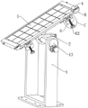
FIG. 1 is a schematic view of a solar panel apparatus according to the present invention;
FIG. 2 is a schematic sectional view of the structure of the fixing base and the locking mechanism of the present invention;
FIG. 3 is an enlarged view of the structure at A in FIG. 2;
FIG. 4 is a schematic view of a mounting bracket and rotating mechanism of the present invention;
FIG. 5 is an exploded view of the mounting and locking mechanism of the present invention;
FIG. 6 is a schematic cross-sectional view of a solar panel apparatus of the present invention;
FIG. 7 is an enlarged view of the structure at B in FIG. 6;
fig. 8 is an enlarged view of the structure at C in fig. 6.
In the figure: 1. mounting a bracket; 11. a cross bar; 12. positioning holes; 13. a protective shell; 14. a transmission gear; 15. a main gear; 2. a fixed seat; 21. positioning the cylinder; 22. a locking groove; 23. a thread groove; 24. a support frame; 3. a semi-annular snap gauge; 31. a sector-shaped tooth block; 32. locking the tooth block; 33. a concave plate; 34. a limiting rod; 35. a limiting circular plate; 36. a locking spring; 37. locking the screw; 4. a protective base; 41. a limiting groove; 42. a pull rod; 43. a positioning spring; 44. positioning a fixture block; 5. a solar panel body; 51. a card slot; 6. a circular block; 61. a circular groove; 62. a set screw; 63. and (4) sucking discs.
Detailed Description
The technical solutions in the embodiments of the present invention will be clearly and completely described below with reference to the drawings in the embodiments of the present invention, and it is obvious that the described embodiments are only a part of the embodiments of the present invention, and not all of the embodiments. All other embodiments, which can be derived by a person skilled in the art from the embodiments given herein without making any creative effort, shall fall within the protection scope of the present invention.
Referring to fig. 1 to 8, the present invention provides a technical solution: the utility model provides a can inhale fixed solar panel equipment certainly, includes installing support 1, and the upper end of 1 inboards of installing support is connected with horizontal pole 11 through the round pin hub rotation, and locating hole 12 has been seted up to the upper end of horizontal pole 11, and the side welding of installing support 1 has protective housing 13, is provided with rotary mechanism in the protective housing 13, and rotary mechanism is including: the solar panel comprises a transmission gear 14 and a main gear 15, the transmission gear 14 is rotatably connected to a protective shell 13, the transmission gear 14 is fixedly connected with a cross rod 11 through a pin shaft, the main gear 15 is meshed at the lower end of the transmission gear 14, the main gear 15 is rotatably connected with the protective shell 13 through a motor shaft, a sunlight sensor is mounted on the side surface of the protective shell 13, the motor is controlled through the cooperation of the sunlight sensor and a PLC (programmable logic controller), the motor shaft in the motor rotates along with sunlight, even if the solar panel main body 5 rotates along with the illumination angle of the sunlight, the sunlight can irradiate on the solar panel main body 5 for a long time, and the power generation efficiency of the solar panel is improved.
Install fixing base 2 on horizontal pole 11, the lower extreme welding of fixing base 2 has positioning cylinder 21, a plane has been seted up for the upper end of a circular rod to horizontal pole 11, 2 joints of fixing base are in the upper end of horizontal pole 11, positioning cylinder 21 pegs graft with locating hole 12, when needs are installed fixing base 2, positioning cylinder 21 that makes 2 lower extremes of fixing base insert along the locating hole 12 of horizontal pole 11, make the installation that fixing base 2 can be accurate, prevent solar panel main part 5 when rotatory simultaneously, fixing base 2 rocks.
Locking groove 22 has been seted up to the lower extreme of fixing base 2, and threaded groove 23 has been seted up in running through to the side in locking groove 22, and the welding of the upper end of fixing base 2 has support frame 24, and the lower extreme of fixing base 2 is provided with locking mechanism, and locking mechanism is including: the semi-annular clamping plate 3, the fan-shaped tooth blocks 31, the locking tooth blocks 32, the concave plates 33, the limiting rods 34, the limiting circular plates 35, the locking springs 36 and the locking screws 37, the semi-annular clamping plate 3 is rotatably connected to the lower end of the fixing seat 2 through a pin shaft, the semi-annular clamping plate 3 is clamped with the cross rod 11, the anti-slip pads are bonded on the inner side of the semi-annular clamping plate 3, the fan-shaped tooth blocks 31 are welded at one end of the semi-annular clamping plate 3, the fan-shaped tooth blocks 31 are clamped with the locking grooves 22, the locking tooth blocks 32 are arranged in the locking grooves 22, the concave plates 33 are welded on the side faces of the locking tooth blocks 32, the limiting rods 34 are slidably connected on the side faces of the concave plates 33, the limiting circular plates 35 are welded at one ends of the limiting rods 34 through the concave plates 33, the locking tooth blocks 32 are slidably connected with the locking grooves 22, the locking tooth blocks 32 are clamped with the fan-shaped tooth blocks 31, the limiting circular plates 35 are slidably connected with the concave plates 33, the diameter of the limiting rods 34 is smaller than the inner diameter of the threaded grooves 23, the limiting rod 34 is sleeved with a locking spring 36, the thread groove 23 is connected with a locking screw 37 in a threaded manner, one end of the locking screw 37 penetrates through the thread groove 23 to be welded with the limiting rod 34, one end of the locking spring 36 is welded with the concave plate 33, the other end of the locking spring 36 is welded with the locking groove 22, and the locking spring 36 applies elasticity to the concave plate 33.
There is protection base 4 in the upper end of support frame 24 through bolted connection, and a pair of spacing groove 41 has been seted up to protection base 4's both ends symmetry, is provided with positioning mechanism in the spacing groove 41, and positioning mechanism is including: the protection base comprises a pull rod 42, a positioning spring 43 and a positioning fixture block 44, a pair of pull rods 42 is symmetrically inserted at two ends of the protection base 4, one end of each pull rod 42 is sleeved with the positioning spring 43, one end of each pull rod 42 is welded with the positioning fixture block 44, the positioning spring 43 is arranged in the limiting groove 41, the positioning fixture blocks 44 are in sliding connection with the limiting groove 41, the positioning fixture blocks 44 are clamped with the clamping grooves 51, the pull rods 42 are in sliding connection with the protection base 4, one end of each positioning spring 43 is inserted with the limiting groove 41, the other end of each positioning spring 43 is inserted with the positioning fixture blocks 44, and the positioning springs 43 apply elasticity to the positioning fixture blocks 44.
Install solar panel main part 5 in the protection base 4, draw-in groove 51 has been seted up to the both ends symmetry of solar panel main part 5, and the lower extreme symmetry of protection base 4 is provided with a pair of self-priming fixed establishment, and self-priming fixed establishment is including: circular block 6, circular recess 61, set screw 62 and sucking disc 63, the welding of the lower extreme bilateral symmetry of protection base 4 has a pair of circular block 6, circular recess 61 has been seted up to the upper end of circular block 6, be provided with sucking disc 63 in the circular recess 61, the side threaded connection of circular block 6 has set screw 62, set screw 62's one end is passed through the convex block and is rotated with sucking disc 63 and be connected, the upper end of sucking disc 63 adsorbs with the side of solar panel main part 5 and is connected, a pair of circular logical groove has been seted up to protection base 4 bottom plate bilateral symmetry, circular block 6 sets up the tip at circular logical groove.
The main gear 15 is driven to rotate through the motor shaft, the main gear 15 drives the transmission gear 14 to rotate, the transmission gear 14 drives the cross rod 11 to rotate, the cross rod 11 drives the fixing seat 2 and the supporting frame 24 to rotate, and the supporting frame 24 drives the protection base 4 and the solar panel main body 5 to rotate, so that the solar panel main body 5 rotates along with the irradiation angle of sunlight, the sunlight can irradiate on the solar panel main body 5 for a long time, and the power generation efficiency of the solar panel is improved;
when the solar panel main body 5 is installed, the solar panel main body 5 is clamped along the protection base 4, the positioning fixture block 44 is clamped with the clamping groove 51 of the solar panel main body 5 under the action of the elastic force of the positioning spring 43, the solar panel main body 5 is firmly fixed with the protection base 4 through the arranged positioning mechanism, the solar panel main body 5 extrudes the sucker 63 in the installation process of the solar panel main body 5, the sucker 63 is firmly adsorbed on the side surface of the solar panel main body 5, then the fixing screw 62 is screwed out of the circular block 6, the fixing screw 62 drives one end of the sucker 63 to move, the sucker 63 is slowly opened, the adsorption force of the sucker 63 on the solar panel main body 5 is increased, and the solar panel main body 5 is firmly fixed with the protection base 4 through the matching of the arranged positioning mechanism and the self-absorption fixing mechanism, so that the operation is simple and convenient; the solar panel equipment structure is a detachable structure, later maintenance and replacement are convenient, when the protective base 4 and the solar panel main body 5 need to be detached from the cross rod 11, the locking screw 37 is firstly screwed out of the fixed seat 2, after the locking screw 37 is completely screwed out of the thread groove 23, the locking screw 37 is pulled, the locking screw 37 drives the limiting rod 34 to move, the limiting rod 34 drives the concave plate 33 to move through the limiting circular plate 35, the concave plate 33 drives the locking tooth block 32 to move, so that the locking tooth block 32 is separated from the fan-shaped tooth block 31, and at the moment, the semi-annular clamping plate 3 can be conveniently rotated downwards, so that the fixed seat 2 can be conveniently detached from the cross rod 11; when the solar panel equipment needs to be installed, the installation support 1 is fixed on the ground or the connecting frame, the fixed seat 2 is clamped at the upper end of the cross rod 11, the semi-annular clamping plate 3 is rotated upwards, the fan-shaped tooth block 31 is clamped along the locking groove 22, meanwhile, the fan-shaped tooth block 31 pushes the locking tooth block 32 to slide along the locking groove 22, the locking tooth block 32 pushes the concave plate 33 to move, the concave plate 33 extrudes the locking spring 36, after the fan-shaped tooth block 31 is completely clamped in the locking groove 22, the locking tooth block 32 is clamped with the fan-shaped tooth block 31 under the action of the elastic force of the locking spring 36, the locking screw 37 is screwed into the fixed seat 2, the locking screw 37 pushes the limiting rod 34 and the limiting circular plate 35 to move, the limiting circular plate 35 firmly supports against the concave plate 33, the concave plate 33 supports against the locking tooth block 32, and accordingly, the locking tooth block 32 is firmly clamped with the fan-shaped tooth block 31, thereby firmly fixing the fixed seat 2 with the cross rod 11.
Although embodiments of the present invention have been shown and described, it will be appreciated by those skilled in the art that changes, modifications, substitutions and alterations can be made in these embodiments without departing from the principles and spirit of the invention, the scope of which is defined in the appended claims and their equivalents.
Claims (9)
1. The utility model provides a can inhale fixed solar panel equipment certainly, includes the installing support, its characterized in that: the upper end of the inner side of the mounting support is rotatably connected with a cross rod through a pin shaft, the upper end of the cross rod is provided with a positioning hole, and a protective shell is welded on the side surface of the mounting support;
the solar panel protection device is characterized in that a rotating mechanism is arranged in the protection shell, a fixing seat is installed on the cross rod, a positioning cylinder is welded at the lower end of the fixing seat, a locking groove is formed in the lower end of the fixing seat, a threaded groove is formed in the side face of the locking groove in a penetrating mode, a supporting frame is welded at the upper end of the fixing seat, a locking mechanism is arranged at the lower end of the fixing seat, a protection base is connected to the upper end of the supporting frame through bolts, a pair of limiting grooves are symmetrically formed in the two ends of the protection base, a positioning mechanism is arranged in each limiting groove, a solar panel main body is installed in each protection base, clamping grooves are symmetrically formed in the two ends of each solar panel main body, and a pair of self-suction fixing mechanisms is symmetrically arranged at the lower end of each protection base.
2. The self-priming fixable solar panel apparatus according to claim 1, wherein: the rotary mechanism comprises: the protective shell is rotatably connected with a transmission gear, the transmission gear is fixedly connected with the cross rod through a pin shaft, the lower end of the transmission gear is meshed with the main gear, and the main gear is rotatably connected with the protective shell through a motor shaft.
3. The self-priming fixable solar panel apparatus according to claim 1, wherein: the upper end of the round rod of the cross rod is provided with a plane, the fixing seat is clamped at the upper end of the cross rod, and the positioning cylinder is inserted into the positioning hole.
4. The self-priming fixable solar panel apparatus according to claim 1, wherein: the locking mechanism comprises: semi-annular cardboard, fan-shaped tooth piece, locking tooth piece, concave plate, gag lever post, spacing plectane, locking spring and locking screw, the lower extreme of fixing base rotates through the round pin axle and is connected with semi-annular cardboard, the one end welding of semi-annular cardboard has fan-shaped tooth piece, fan-shaped tooth piece and locking groove joint, the locking inslot is provided with the locking tooth piece, the side welding of locking tooth piece has the concave plate, the side sliding connection of concave plate has the gag lever post, the one end of gag lever post is passed concave plate welding and is had spacing plectane, the cover is equipped with locking spring on the gag lever post, thread groove female connection has locking screw, locking screw's one end is passed thread groove and is welded with the gag lever post.
5. The self-priming fixable solar panel apparatus according to claim 4, wherein: the semi-annular clamping plate is clamped with the cross rod, and the inner side of the semi-annular clamping plate is bonded with the non-slip mat.
6. The self-priming fixable solar panel apparatus according to claim 5, wherein: locking tooth piece and locking groove sliding connection, locking tooth piece and fan-shaped tooth piece joint, spacing plectane and concave plate sliding connection, the diameter of stop lever is less than the internal diameter of thread groove.
7. The self-priming fixable solar panel apparatus according to claim 1, wherein: the positioning mechanism comprises: the protective base comprises a pull rod, positioning springs and positioning fixture blocks, wherein a pair of pull rods are symmetrically inserted into two ends of the protective base, one end of each pull rod is sleeved with one positioning spring, and one end of each pull rod is welded with one positioning fixture block.
8. The self-priming fixable solar panel apparatus according to claim 7, wherein: the positioning spring is arranged in the limiting groove, the positioning clamping block is connected with the limiting groove in a sliding mode, and the positioning clamping block is connected with the clamping groove in a clamping mode.
9. A self-priming fixable solar panel apparatus according to claim 1, characterised in that: the self-suction fixing mechanism comprises: the solar panel protection base comprises a circular block, a circular groove, a fixing screw and a sucker, wherein the pair of circular blocks are symmetrically welded at the left and right sides of the lower end of the protection base, the circular groove is formed in the upper end of each circular block, the sucker is arranged in the circular groove, the fixing screw is connected with the side face of each circular block in a threaded mode, one end of the fixing screw is connected with the sucker in a rotating mode through the convex block, and the upper end of the sucker is connected with the side face of the solar panel main body in an adsorbing mode.
Priority Applications (1)
| Application Number | Priority Date | Filing Date | Title |
|---|---|---|---|
| CN202210421407.6A CN114696732B (en) | 2022-04-21 | 2022-04-21 | Can inhale fixed solar panel equipment certainly |
Applications Claiming Priority (1)
| Application Number | Priority Date | Filing Date | Title |
|---|---|---|---|
| CN202210421407.6A CN114696732B (en) | 2022-04-21 | 2022-04-21 | Can inhale fixed solar panel equipment certainly |
Publications (2)
| Publication Number | Publication Date |
|---|---|
| CN114696732A true CN114696732A (en) | 2022-07-01 |
| CN114696732B CN114696732B (en) | 2022-09-20 |
Family
ID=82144027
Family Applications (1)
| Application Number | Title | Priority Date | Filing Date |
|---|---|---|---|
| CN202210421407.6A Active CN114696732B (en) | 2022-04-21 | 2022-04-21 | Can inhale fixed solar panel equipment certainly |
Country Status (1)
| Country | Link |
|---|---|
| CN (1) | CN114696732B (en) |
Cited By (1)
| Publication number | Priority date | Publication date | Assignee | Title |
|---|---|---|---|---|
| CN116582067A (en) * | 2023-07-03 | 2023-08-11 | 中铁电气化局集团第一工程有限公司 | Connect fast mode photovoltaic board mounting structure on water soon |
Citations (5)
| Publication number | Priority date | Publication date | Assignee | Title |
|---|---|---|---|---|
| CN111003044A (en) * | 2019-12-31 | 2020-04-14 | 蔡燕旋 | Solar panel mounting and positioning device and positioning method thereof |
| CN213461642U (en) * | 2020-12-04 | 2021-06-15 | 简凯纳 | Solar panel capable of rotating along with sun |
| WO2022045588A1 (en) * | 2020-08-28 | 2022-03-03 | 신정훈 | Solar photovoltaic rotation device having backlash control structure |
| CN114157225A (en) * | 2021-12-08 | 2022-03-08 | 滁州学院 | Photovoltaic solar panel self-adaptive adjusting device and implementation method thereof |
| CN216048435U (en) * | 2021-08-06 | 2022-03-15 | 淮安瑞鑫光伏科技有限公司 | Solar panel protective bracket |
-
2022
- 2022-04-21 CN CN202210421407.6A patent/CN114696732B/en active Active
Patent Citations (5)
| Publication number | Priority date | Publication date | Assignee | Title |
|---|---|---|---|---|
| CN111003044A (en) * | 2019-12-31 | 2020-04-14 | 蔡燕旋 | Solar panel mounting and positioning device and positioning method thereof |
| WO2022045588A1 (en) * | 2020-08-28 | 2022-03-03 | 신정훈 | Solar photovoltaic rotation device having backlash control structure |
| CN213461642U (en) * | 2020-12-04 | 2021-06-15 | 简凯纳 | Solar panel capable of rotating along with sun |
| CN216048435U (en) * | 2021-08-06 | 2022-03-15 | 淮安瑞鑫光伏科技有限公司 | Solar panel protective bracket |
| CN114157225A (en) * | 2021-12-08 | 2022-03-08 | 滁州学院 | Photovoltaic solar panel self-adaptive adjusting device and implementation method thereof |
Cited By (2)
| Publication number | Priority date | Publication date | Assignee | Title |
|---|---|---|---|---|
| CN116582067A (en) * | 2023-07-03 | 2023-08-11 | 中铁电气化局集团第一工程有限公司 | Connect fast mode photovoltaic board mounting structure on water soon |
| CN116582067B (en) * | 2023-07-03 | 2024-04-09 | 中铁电气化局集团第一工程有限公司 | Connect fast mode photovoltaic board mounting structure on water soon |
Also Published As
| Publication number | Publication date |
|---|---|
| CN114696732B (en) | 2022-09-20 |
Similar Documents
| Publication | Publication Date | Title |
|---|---|---|
| CN114696732B (en) | Can inhale fixed solar panel equipment certainly | |
| CN212963969U (en) | Automatic plugging mechanism for plugging service life detector | |
| CN210469202U (en) | Photovoltaic support with adjustable rotate | |
| CN111911792A (en) | Monitoring equipment's for construction steel platform mounting structure | |
| CN218760219U (en) | Novel wind driven generator | |
| CN210578373U (en) | Rotation type photovoltaic power generation board installing support | |
| CN211423344U (en) | Electric automobile generator wheel groove sheath subassembly | |
| CN207724185U (en) | A kind of curtain wall test specimen frame installation gripping mechanism | |
| CN210290980U (en) | Multifunctional pipeline supporting and hanging frame | |
| CN220629215U (en) | Novel photovoltaic mounting support | |
| CN215771914U (en) | Electric power safety early warning device | |
| CN209831343U (en) | Labor-saving lever mechanism | |
| CN218181630U (en) | Geological disaster monitoring instrument | |
| CN220019180U (en) | Motor shaft strength test fixture | |
| CN216793756U (en) | Fuel cell system assembling tool | |
| CN219079257U (en) | Filler support for high-efficiency sewage treatment aeration tank | |
| CN211343751U (en) | Bearing seat capable of being rapidly disassembled | |
| CN220896272U (en) | Cable support for power construction | |
| CN218061290U (en) | Simple to operate's construction wheel buckle scaffold | |
| CN215617554U (en) | Well jar anchor clamps convenient to it is fixed | |
| CN219394764U (en) | Angle-adjustable solar photovoltaic power generation panel bracket | |
| CN215420149U (en) | Automatic turned angle's photovoltaic support | |
| CN219611683U (en) | Maintainable photovoltaic solar tracker | |
| CN219747667U (en) | Steel pipe mounting fixture | |
| CN220112893U (en) | Polishing device for street lamp pole |
Legal Events
| Date | Code | Title | Description |
|---|---|---|---|
| PB01 | Publication | ||
| PB01 | Publication | ||
| SE01 | Entry into force of request for substantive examination | ||
| SE01 | Entry into force of request for substantive examination | ||
| GR01 | Patent grant | ||
| GR01 | Patent grant |