CN114682722A - Red online trimming mechanism that dashes - Google Patents
Red online trimming mechanism that dashes Download PDFInfo
- Publication number
- CN114682722A CN114682722A CN202210473270.9A CN202210473270A CN114682722A CN 114682722 A CN114682722 A CN 114682722A CN 202210473270 A CN202210473270 A CN 202210473270A CN 114682722 A CN114682722 A CN 114682722A
- Authority
- CN
- China
- Prior art keywords
- trimming
- die
- seat
- side cut
- top die
- Prior art date
- Legal status (The legal status is an assumption and is not a legal conclusion. Google has not performed a legal analysis and makes no representation as to the accuracy of the status listed.)
- Pending
Links
Images


Classifications
-
- B—PERFORMING OPERATIONS; TRANSPORTING
- B21—MECHANICAL METAL-WORKING WITHOUT ESSENTIALLY REMOVING MATERIAL; PUNCHING METAL
- B21J—FORGING; HAMMERING; PRESSING METAL; RIVETING; FORGE FURNACES
- B21J5/00—Methods for forging, hammering, or pressing; Special equipment or accessories therefor
- B21J5/02—Die forging; Trimming by making use of special dies ; Punching during forging
-
- B—PERFORMING OPERATIONS; TRANSPORTING
- B21—MECHANICAL METAL-WORKING WITHOUT ESSENTIALLY REMOVING MATERIAL; PUNCHING METAL
- B21J—FORGING; HAMMERING; PRESSING METAL; RIVETING; FORGE FURNACES
- B21J13/00—Details of machines for forging, pressing, or hammering
-
- B—PERFORMING OPERATIONS; TRANSPORTING
- B21—MECHANICAL METAL-WORKING WITHOUT ESSENTIALLY REMOVING MATERIAL; PUNCHING METAL
- B21J—FORGING; HAMMERING; PRESSING METAL; RIVETING; FORGE FURNACES
- B21J13/00—Details of machines for forging, pressing, or hammering
- B21J13/04—Frames; Guides
-
- B—PERFORMING OPERATIONS; TRANSPORTING
- B21—MECHANICAL METAL-WORKING WITHOUT ESSENTIALLY REMOVING MATERIAL; PUNCHING METAL
- B21J—FORGING; HAMMERING; PRESSING METAL; RIVETING; FORGE FURNACES
- B21J13/00—Details of machines for forging, pressing, or hammering
- B21J13/08—Accessories for handling work or tools
- B21J13/10—Manipulators
-
- B—PERFORMING OPERATIONS; TRANSPORTING
- B21—MECHANICAL METAL-WORKING WITHOUT ESSENTIALLY REMOVING MATERIAL; PUNCHING METAL
- B21J—FORGING; HAMMERING; PRESSING METAL; RIVETING; FORGE FURNACES
- B21J13/00—Details of machines for forging, pressing, or hammering
- B21J13/08—Accessories for handling work or tools
- B21J13/14—Ejecting devices
-
- B—PERFORMING OPERATIONS; TRANSPORTING
- B21—MECHANICAL METAL-WORKING WITHOUT ESSENTIALLY REMOVING MATERIAL; PUNCHING METAL
- B21J—FORGING; HAMMERING; PRESSING METAL; RIVETING; FORGE FURNACES
- B21J5/00—Methods for forging, hammering, or pressing; Special equipment or accessories therefor
- B21J5/02—Die forging; Trimming by making use of special dies ; Punching during forging
- B21J5/027—Trimming
-
- F—MECHANICAL ENGINEERING; LIGHTING; HEATING; WEAPONS; BLASTING
- F16—ENGINEERING ELEMENTS AND UNITS; GENERAL MEASURES FOR PRODUCING AND MAINTAINING EFFECTIVE FUNCTIONING OF MACHINES OR INSTALLATIONS; THERMAL INSULATION IN GENERAL
- F16P—SAFETY DEVICES IN GENERAL; SAFETY DEVICES FOR PRESSES
- F16P1/00—Safety devices independent of the control and operation of any machine
- F16P1/02—Fixed screens or hoods
Abstract
The invention provides a red punching online trimming mechanism, and belongs to the technical field of edge trimmers. The trimming mechanism comprises a frame, a trimming mechanism seat is arranged on the frame, a forming area is arranged on the trimming mechanism seat, a trimming section die is arranged in the forming area, a trimming forming through groove for trimming and forming parts is formed in the trimming section die, and a trimming top die is arranged above the trimming section die. The red punching machine punches products at the trimming section mould department of shaping district and can lead to the groove department at the trimming shaping and stereotype out and wait to cut the limit product, the sideslip mechanism can remove the trimming section mould to trimming top mould downside after accomplishing the punching press, the vertical lift mechanism drive trimming top mould pushes down can cut edge the product of waiting to cut the limit in the groove and will accomplish the ejecting of product to ejection of compact structure department from the trimming shaping logical inslot ejecting of product after cutting edge of trimming, thereby can make trimming mechanism and red punching machine realize the linkage through setting up the sideslip mechanism and can effectively improve the production efficiency of product.
Description
Technical Field
The invention belongs to the technical field of edge cutters and relates to a red punching online edge cutting mechanism.
Background
"hong Chong" is a new noun whose origin is difficult to find in a dictionary. Since the red punching process is an advanced professional process which is just developed from the modern precision forging and hot extrusion. With the advance of society and the development of science and technology, the mechanical industry puts forward new mechanical strength requirements on mechanical parts. The mechanical strength is improved by two methods, namely, the material of the parts is changed, and the processing method is changed. The red punching process is one of effective methods for improving the mechanical property of parts by changing the processing method, so that the red punching process has strong vitality and good development prospect as the forging process. The red punching process is a process of heating a metal blank and then forming the metal blank in a die like a finish forging process, but the red punching process generally adopts one-time forming except a large red punching part, and the finish forging process generally adopts several times of pressure forming.
The product that forms through red punching press generally can form the overlap, gets rid of the overlap of product among the prior art and needs two steps, at first need take out the product that the red punching press formed from the red punching machine earlier, and the manual work is sent to the bead cutter and is cut edge, and degree of automation is lower, wastes time and energy.
In order to overcome the defects of the prior art, people continuously explore and provide various solutions, for example, a chinese patent discloses an automatic punching and cutting waste device with a protective structure for producing a glasses packaging box [ application number: 202021912454.3], including supporting seat and die-cut base, the supporting seat top is provided with the transmission band, die-cut die holder top middle-end is provided with die-cut piece, and die-cut die holder top inboard has seted up the punching groove, die-cut base is settled at the fixed plate top, and die-cut base outside top is provided with down the echelette, die-cut roof bottom avris is connected with last echelette, die-cut base bottom middle-end is connected with the die-cutting sword, but also has above-mentioned problem.
Disclosure of Invention
The invention aims to solve the problems and provides an online trimming mechanism of a red punch.
In order to achieve the purpose, the invention adopts the following technical scheme:
the utility model provides a red online trimming mechanism that dashes, includes the frame, is equipped with the trimming mechanism seat in the frame, the trimming mechanism seat on be equipped with the shaping district, be equipped with the side cut section mould in the shaping district, the side cut section mould on be equipped with the side cut shaping that is used for the part side cut to finalize the design and lead to the groove, side cut section mould top be equipped with the side cut top die, side cut top die link to each other with vertical lift mechanism, side cut section mould below be equipped with ejection of compact structure, the side cut section mould on be connected with and drive the side cut section mould and shift out the sideslip mechanism that the shaping district got the material.
In the red punching online trimming mechanism, the vertical lifting mechanism comprises a gas-liquid pressure cylinder arranged on the rack, a driving shaft of the gas-liquid pressure cylinder is connected with the trimming top die, and a driving shaft guide structure is arranged between the driving shaft of the gas-liquid pressure cylinder and the rack.
In the above-mentioned online trimming mechanism with red punching, the driving shaft guide structure comprises a square upper plate of the trimming mechanism arranged between a pneumatic-hydraulic cylinder and a trimming top die, a guide seat is fixed on the upper plate of the trimming mechanism, and the pneumatic-hydraulic cylinder driving shaft is arranged on the guide seat in a penetrating manner and connected with the trimming top die.
In the above-mentioned online trimming mechanism of red punching, the trimming section mould is provided with at least one trimming forming through groove for trimming and shaping the part, the bottom of the trimming top mould is provided with at least one trimming ejecting piece for ejecting the part, and the trimming forming through groove and the trimming ejecting piece are arranged in a one-to-one correspondence manner.
In the above-mentioned online trimming mechanism of punching red, the side cut section mould on seted up four and be the side cut shaping logical groove that the rectangle array distributes, side cut top die bottom be equipped with four and be the side cut liftout that the rectangle array distributes and be used for ejecting part.
The cross sections of the four trimming ejecting pieces and the four trimming forming through grooves are L-shaped, and the length of the trimming ejecting pieces is greater than the depth of the trimming forming through grooves.
In the red punching online trimming mechanism, the trimming top die is sleeved with a chip-preventing cover fixed on the frame, and a secondary guide assembly is arranged between the chip-preventing cover and the trimming top die.
The secondary direction subassembly including set up on the chip-proof cover four around the circumferencial direction on evenly distributed's the bar lead to the groove, side cut top die on be equipped with four and be on a parallel with the bottom surface can bar lead to groove complex guide bar.
In foretell red online trimming mechanism that dashes, ejection of compact structure including setting up two through-holes on the trimming mechanism seat, two through-holes are separated through the stiffener, are equipped with the play hopper of fixing on the trimming mechanism seat below two through-holes.
In the above-mentioned red-punching online trimming mechanism, the traverse mechanism comprises a traverse slide rail connected with the trimming section die, the traverse slide rail is connected with two traverse sliders, the two traverse sliders are fixed on a discharging hand slide pedestal connected with the trimming mechanism seat, and a traverse driving assembly is arranged between the traverse sliders and the traverse slide rail.
In the above-mentioned red punching on-line trimming mechanism, the traverse driving assembly includes a rack fixed on the traverse slide rail, a driving gear is provided on the rack, and the driving gear is connected with the driving motor.
In the above-mentioned online trimming mechanism of red punching, the ejection of compact slide bench seat link to each other with the trimming mechanism seat through the slip table connecting plate that is L shape, still be equipped with on the slip table connecting plate and strengthen support piece, the slip table connecting plate link to each other with frame vertical lift mechanism.
Compared with the prior art, the invention has the advantages that:
1. the red punching machine can punch products at the trimming section die of the forming area and can form products to be cut at the trimming section forming through groove, the transverse moving mechanism can move the trimming section die to the lower side of the trimming top die after punching is completed, the vertical lifting mechanism drives the trimming top die to downwards press the trimming top die, the products to be cut in the trimming section forming through groove can be trimmed, the products after trimming are ejected from the trimming section forming through groove to the ejection of the products at the discharging structure, and the transverse moving mechanism can enable the trimming mechanism and the red punching machine to be linked, so that the production efficiency of the products can be effectively improved.
2. Set up four and cut edge shaping and lead to four products of groove ability one-time stamping forming, can improve the production efficiency of product, four are cut edge shaping and lead to the groove and be rectangular array distribution and can prevent the overlap of product and influence each other, and the length that the ejecting piece of side cut is greater than the degree of depth that the groove was led to in the shaping of side cut and can ensure that the product can follow that the groove is ejecting in the shaping of side cut.
3. Prevent that the overlap that the bits cover can prevent to cut off from the product from splashing and lead to operator's injury or influence sanitation, secondary guide subassembly can further carry on spacingly to the side cut top mould, receives the offset of marcing position after the recoil force when preventing that side cut top mould from pushing down.
4. The vertical lifting mechanism of the rack can drive the trimming mechanism seat to lift along the vertical direction through the sliding table connecting plate, the height of the trimming mechanism seat can be adjusted to enable the equipment to be suitable for the red punching machines with different heights, and the reinforced supporting piece can improve the bearing of the sliding table connecting plate.
Additional advantages, objects, and features of the invention will be set forth in part in the description which follows and in part will become apparent to those having ordinary skill in the art upon examination of the following or may be learned from practice of the invention.
Drawings
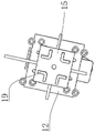
FIG. 1 is a three-dimensional view of the present invention;
FIG. 2 is a three-dimensional view of another aspect of the invention;
FIG. 3 is a schematic view of the upper plate of the trimming mechanism;
fig. 4 is a schematic structural view of the frame vertical lifting mechanism.
In the figure, a trimming mechanism seat 1, a vertical lifting mechanism 2, a trimming die 3, a traversing mechanism 4, a driving motor 6, a traversing slide rail 8, a driving gear 9, a rack 10, a traversing slide block 11, a trimming mechanism upper plate 12, a mounting plate 13, a gas-liquid pressure cylinder 14, a trimming top die 15, a trimming forming through groove 18, a trimming ejecting piece 19, a through hole 20, a discharging hopper 21, a chip-proof cover 22, a sliding table connecting plate 24, a discharging hand slide seat 26, a lifting driver 27, a lifting screw 28, a lifting slide block 29, a limiting slide block 30, a vertical slide rail 31, a forming area 100, a rack 200, a discharging structure 201, a driving shaft guide structure 202, a guide seat 203, a secondary guide component 204, a guide rod 205, a reinforcing rod 206, a traversing driving component 207, a reinforcing support piece 208, a rack vertical lifting mechanism 209 and a supporting rod 210.
Detailed Description
As shown in fig. 1 and 2, an online trimming mechanism of red punching comprises a frame 200, a trimming mechanism seat 1 is arranged on the frame 200, a forming area 100 is arranged on the trimming mechanism seat 1, a trimming section die 3 is arranged in the forming area 100, a trimming forming through groove 18 for trimming and shaping a part is arranged on the trimming section die 3, a trimming top die 15 is arranged above the trimming section die 3, the trimming top die 15 is connected with a vertical lifting mechanism 2, a discharging structure 201 is arranged below the trimming section die 3, and a traversing mechanism 4 capable of driving the trimming section die 3 to move out of the forming area 100 for taking a material is connected to the trimming section die 3.
In this embodiment, the red punching machine is at the side cut section mould department punching press product in the shaping district and can pass through 18 departments of the shaping in the side cut shaping and go out the product of waiting to cut the limit, the sideslip mechanism can remove the side cut section mould to side cut top mould downside after accomplishing the punching press, vertical lift mechanism drive side cut top mould pushes down can be with the side cut product of waiting to cut the limit in the side cut shaping logical groove and ejecting to ejection of compact structure department completion product in the logical inslot of the product of accomplishing the side cut, thereby can make trimming mechanism and red punching machine realize the linkage through setting up the sideslip mechanism and can effectively improve the production efficiency of product.
Specifically, as shown in fig. 1 and 2, the vertical lifting mechanism 2 includes an air-liquid pressurizing cylinder 14 disposed on the machine frame 200, a driving shaft of the air-liquid pressurizing cylinder 14 is connected to the trimming top die 15, and a driving shaft guide 202 is disposed between the driving shaft of the air-liquid pressurizing cylinder 14 and the machine frame 200. The gas-liquid pressure cylinder 14 can drive the edge cutting top die to lift along the vertical direction, and can limit the edge cutting top die through the driving shaft guide structure when the edge cutting top die acts.
Specifically, the driving shaft guide structure 202 comprises a square upper plate 12 of the trimming mechanism arranged between the pneumatic and hydraulic cylinder 14 and the trimming top die 15, a guide seat 203 is fixed on the upper plate 12 of the trimming mechanism, and the driving shaft of the pneumatic and hydraulic cylinder 14 is arranged on the guide seat 203 in a penetrating manner and connected with the trimming top die 15. The trimming top die can penetrate through the upper plate of the trimming mechanism in the shape of a square circle, and the guide seat can limit the driver of the gas-liquid pressure cylinder so as to prevent the trimming top die from deviating during action.
Specifically, the top of the upper plate 12 of the edge cutting mechanism is further fixedly connected with four support rods 210 which are uniformly distributed around the circumferential direction, and the top of each of the four support rods 210 is fixedly connected with a mounting plate 13 for mounting a gas-liquid pressurizing cylinder 14.
Preferably, as shown in fig. 1 to fig. 3, at least one trimming forming through groove 18 for trimming and shaping the part is formed in the trimming die 3, at least one trimming ejecting member 19 for ejecting the part is arranged at the bottom of the trimming ejecting die 15, and the trimming forming through grooves 18 and the trimming ejecting members 19 are arranged in a one-to-one correspondence manner. The trimming ejection piece corresponding to the trimming through groove can eject the main body of the product in the trimming through groove, and can cut off the flash on the product through the trimming through groove and the trimming die.
Specifically, the trimming die 3 is provided with four trimming forming through grooves 18 distributed in a rectangular array, and the bottom of the trimming top die 15 is provided with four trimming ejecting pieces 19 distributed in a rectangular array and used for ejecting parts. The cross-sections of the four trimming ejectors 19 and the four trimming forming through grooves 18 are L-shaped, and the length of the trimming ejectors 19 is greater than the depth of the trimming forming through grooves 18.
Four trimming forming through grooves are arranged to punch and form four products at one time, the production efficiency of the products can be improved, the four trimming forming through grooves are distributed in a rectangular array mode and can prevent the overlap of the products from influencing each other, and the length of the trimming ejecting piece 19 is larger than the depth of the trimming forming through groove 18, so that the products can be ejected out of the trimming forming through grooves.
Preferably, as shown in fig. 1 and 2, the periphery of the trimming top die 15 is sleeved with a chip-preventing cover 22 fixed on the frame 200, and a secondary guide assembly 204 is arranged between the chip-preventing cover 22 and the trimming top die 15. The scrap-proof cover 22 can prevent the situation that the flying edge cut off from the product splashes to cause injury to an operator or influence environmental sanitation, and the secondary guide assembly 204 can further limit the trimming top die and prevent the deviation of the traveling position after the trimming top die is pressed down by the recoil force.
Specifically, the secondary guide assembly 204 comprises four strip-shaped through grooves uniformly distributed in the circumferential direction on the chip-proof cover 22, and four guide rods 205 which are parallel to the bottom surface and can be matched with the strip-shaped through grooves are arranged on the trimming top die 15. Can carry on spacingly to side cut top die through the bar logical groove cooperation guide bar that sets up on preventing the bits groove.
Specifically, as shown in fig. 1 and fig. 2, the discharging structure 201 includes two through holes 20 disposed on the trimming mechanism seat 1, the two through holes 20 are separated by a reinforcing rod 206, and a discharging hopper 21 fixed on the trimming mechanism seat 1 is disposed below the two through holes 20. The two through holes on the trimming mechanism seat correspond to the two trimming forming through grooves respectively, and products ejected out of the trimming forming through grooves can fall down from the through holes and are guided to the product output mechanism or the product collecting device through the discharge hopper in a unified mode.
Specifically, as shown in fig. 1, 2 and 4, the traverse mechanism 4 includes a traverse slide 8 connected to the trimming die 3, the traverse slide 8 is connected to two traverse sliders 11, the two traverse sliders 11 are fixed to a discharging slide base 26 connected to the trimming mechanism base 1, and a traverse driving assembly 207 is provided between the traverse sliders 11 and the traverse slide 8.
The sideslip drive assembly on ejection of compact hand sliding pedestal 26 can drive sideslip slide rail 8 along the reciprocal sideslip of horizontal direction thereby can drive the reciprocal switching between the red towards machine in shaping district and the side cut top mould downside of side cut section of mould, and sideslip slider 11 can carry out spacingly to sideslip slide rail 8.
Specifically, the traverse driving assembly 207 comprises a rack 10 fixed on the traverse slide rail 8, a driving gear 9 is arranged on the rack 10, and the driving gear 9 is connected with the driving motor 6. The driving motor 6 can drive the driving gear to rotate, the driving gear can drive the rack to move, and the rack can drive the transverse moving sliding rail to move transversely in a reciprocating mode in the horizontal direction.
Preferably, as shown in fig. 4, the discharging hand-sliding table base 26 is connected with the trimming mechanism base 1 through an L-shaped sliding table connecting plate 24, a reinforcing support member 208 is further arranged on the sliding table connecting plate 24, and the sliding table connecting plate 24 is connected with a rack vertical lifting mechanism 209. The vertical lifting mechanism 209 of the rack can drive the trimming mechanism seat 1 to lift along the vertical direction through the sliding table connecting plate 24, the height of the trimming mechanism seat can be adjusted to enable the device to be suitable for the red punching machines with different heights, and the reinforcing support piece 208 can improve the bearing of the sliding table connecting plate.
Specifically, at least two reinforcing support members 208 are provided on the slip connection plate 24, and the cross section of the reinforcing support members 208 is a right triangle.
Specifically speaking, frame vertical lift mechanism 209 is including setting up the lift driver 27 on ejection of compact hand sliding pedestal 26, the output shaft tip of lift driver 27 link firmly the lifting screw 28 of vertical setting, the spiro union has lifting slide 29 on the lifting screw 28, lifting slide 29 both sides pass through limit slide 30 and slip table connecting plate 24 and link to each other, ejection of compact hand sliding pedestal 26 on still be equipped with two vertical slide rails 31 that link to each other with limit slide 30.
The lifting driver 27 can drive the lifting screw to rotate, the lifting screw can drive the lifting slide block to lift along the vertical direction, the lifting slide block can drive the two limit slide blocks to lift along the vertical direction by lifting along the vertical direction, the limit slide block can drive the sliding table connecting plate 24 to lift along the vertical direction by lifting, and the vertical slide rail can limit the limit slide block so as to prevent the sliding table connecting plate 24 from deviating during movement.
The working principle of the invention is as follows: the red punching machine punches a product at the trimming section die of the forming area and can form a product to be trimmed at the trimming section forming through groove 18, the transverse moving mechanism can move the trimming section die to the lower side of the trimming top die after punching is completed, the vertical lifting mechanism drives the trimming top die to press downwards, the product to be trimmed in the trimming section forming through groove can be trimmed, the product after trimming is ejected out from the trimming section forming through groove to the discharging structure, and ejection of the product is completed, and the trimming mechanism and the red punching machine can be linked by arranging the transverse moving mechanism, so that the production efficiency of the product can be effectively improved;
the pneumatic-hydraulic cylinder 14 can drive the trimming top die to lift in the vertical direction, the trimming top die can be limited through the driving shaft guide structure when the trimming top die acts, the trimming top die can penetrate through the upper plate of the trimming mechanism in a shape of a Chinese character 'hui', a driver of the pneumatic-hydraulic cylinder can be limited by the guide seat so as to prevent the trimming top die from deviating when acting, a trimming ejecting piece arranged corresponding to the trimming forming through groove can eject a product main body in the trimming forming through groove, and burrs on the product can be cut through a shearing surface between the trimming forming through groove and the trimming section die;
the four trimming forming through grooves are arranged, so that four products can be formed in a one-step stamping mode, the production efficiency of the products can be improved, the four trimming forming through grooves are distributed in a rectangular array mode, the mutual influence of the flashes of the products can be prevented, and the length of the trimming ejecting piece 19 is larger than the depth of the trimming forming through groove 18, so that the products can be ejected from the trimming forming through grooves;
the scrap-proof cover 22 can prevent the flying edge cut off from the product from splashing to cause injury to an operator or influence on environmental sanitation, the secondary guide assembly 204 can further limit the edge-cutting top die, the traveling position of the edge-cutting top die is prevented from shifting after the edge-cutting top die is subjected to recoil force when being pressed down, and the edge-cutting top die can be limited by matching a strip-shaped through groove arranged on the scrap-proof groove with a guide rod; the two through holes on the trimming mechanism seat correspond to the two trimming forming through grooves respectively, and products ejected out of the trimming forming through grooves can fall from the through holes and are guided to the product output mechanism or the product collecting device through the discharge hopper in a unified way;
the transverse moving driving assembly on the discharging trolley pedestal 26 can drive the transverse moving slide rail 8 to move transversely in a reciprocating manner along the horizontal direction so as to drive the trimming section die to switch between the red punching machine in the forming area and the lower side of the trimming top die in a reciprocating manner, the transverse moving slide block 11 can limit the transverse moving slide rail 8, the driving motor 6 can drive the driving gear to rotate, the driving gear can drive the rack to move, and the rack can drive the transverse moving slide rail to move transversely in a reciprocating manner along the horizontal direction;
the vertical lifting mechanism 209 of the rack can drive the trimming mechanism seat 1 to lift along the vertical direction through the sliding table connecting plate 24, the height of the trimming mechanism seat can be adjusted to enable the device to be suitable for the red punching machines with different heights, and the reinforcing support piece 208 can improve the bearing of the sliding table connecting plate.
The specific embodiments described herein are merely illustrative of the spirit of the invention. Various modifications or additions may be made to the described embodiments or alternatives may be employed by those skilled in the art without departing from the spirit or ambit of the invention as defined in the appended claims.
Although the trimming mechanism seat 1, the vertical lifting mechanism 2, the trimming section die 3, the traversing mechanism 4, the driving motor 6, the traversing slide rail 8, the driving gear 9, the rack 10, the traversing slide block 11, the trimming mechanism upper plate 12, the mounting plate 13, the gas-liquid pressurizing cylinder 14, the trimming top die 15, the trimming forming through groove 18, the trimming ejecting piece 19, the through hole 20, the discharging hopper 21, the scrap-proof cover 22 and the sliding table connecting plate 24 are used more frequently, the discharging hand-sliding pedestal 26, the lifting driver 27, the lifting screw 28, the lifting slider 29, the limit slider 30, the vertical slide rail 31, the molding zone 100, the frame 200, the discharging structure 201, the driving shaft guide structure 202, the guide seat 203, the secondary guide assembly 204, the guide rod 205, the reinforcing rod 206, the traverse motion driving assembly 207, the reinforcing support member 208, the frame vertical lifting mechanism 209, the support rod 210, etc., which are used merely for convenience of describing and explaining the essence of the present invention; they are to be construed as being without limitation to any additional limitations that may be imposed by the spirit of the present invention.
Claims (10)
1. The utility model provides a red online trimming mechanism that dashes, includes frame (200), its characterized in that is equipped with trimming mechanism seat (1) on frame (200), trimming mechanism seat (1) on be equipped with shaping district (100), be equipped with side cut section mould (3) in shaping district (100), side cut section mould (3) on be equipped with the side cut shaping that is used for the part side cut to finalize the design and lead to groove (18), side cut section mould (3) top be equipped with side cut top die (15), side cut top die (15) link to each other with vertical lift mechanism (2), side cut section mould (3) below be equipped with ejection of compact structure (201), side cut section mould (3) on be connected with and to drive side cut section mould (3) and shift out sideslip mechanism (4) that shaping district (100) were got the material.
2. A red punching on-line trimming mechanism according to claim 1, wherein the vertical lifting mechanism (2) comprises an air-liquid pressurizing cylinder (14) arranged on the frame (200), a driving shaft of the air-liquid pressurizing cylinder (14) is connected with the trimming top die (15), and a driving shaft guide structure (202) is arranged between the driving shaft of the air-liquid pressurizing cylinder (14) and the frame (200).
3. The red punching online trimming mechanism according to claim 2, wherein the driving shaft guide structure (202) comprises a square upper trimming mechanism plate (12) arranged between the pneumatic and hydraulic cylinder (14) and the trimming top die (15), a guide seat (203) is fixed on the upper trimming mechanism plate (12), and the driving shaft of the pneumatic and hydraulic cylinder (14) is arranged on the guide seat (203) in a penetrating way and connected with the trimming top die (15).
4. The red punching online trimming mechanism according to claim 1, 2 or 3, wherein the trimming die (3) is provided with at least one trimming forming through groove (18) for trimming and shaping the part, the bottom of the trimming top die (15) is provided with at least one trimming ejecting member (19) for ejecting the part, and the trimming forming through grooves (18) and the trimming ejecting members (19) are arranged in a one-to-one correspondence manner.
5. The red punching on-line trimming mechanism according to claim 4, wherein the trimming die (3) is provided with four trimming forming through grooves (18) distributed in a rectangular array, and the bottom of the trimming top die (15) is provided with four trimming ejecting pieces (19) distributed in a rectangular array for ejecting parts.
The sections of the four trimming ejecting pieces (19) and the four trimming forming through grooves (18) are L-shaped, and the length of the trimming ejecting pieces (19) is larger than the depth of the trimming forming through grooves (18).
6. The red punching online trimming mechanism according to claim 5, wherein the trimming top die (15) is sleeved with a chip-preventing cover (22) fixed on the frame (200), and a secondary guide assembly (204) is arranged between the chip-preventing cover (22) and the trimming top die (15).
The secondary guide assembly (204) comprises four strip-shaped through grooves which are uniformly distributed on the anti-scrap cover (22) in the circumferential direction, and four guide rods (205) which are parallel to the bottom surface and can be matched with the strip-shaped through grooves are arranged on the trimming top die (15).
7. A red punching on-line trimming mechanism according to claim 6, characterized in that the discharging structure (201) comprises two through holes (20) arranged on the trimming mechanism seat (1), the two through holes (20) are separated by a reinforcing rod (206), and a discharging hopper (21) fixed on the trimming mechanism seat (1) is arranged below the two through holes (20).
8. A red punching on-line trimming mechanism according to claim 1, 2 or 3, wherein the traversing mechanism (4) comprises a traverse slide rail (8) connected with the trimming die (3), the traverse slide rail (8) is connected with two traverse sliders (11), the two traverse sliders (11) are fixed on a discharging hand slide pedestal (26) connected with the trimming mechanism seat (1), and a traverse driving component (207) is arranged between the traverse sliders (11) and the traverse slide rail (8).
9. The red punching on-line trimming mechanism according to claim 8, wherein the traverse driving assembly (207) comprises a rack (10) fixed on the traverse sliding rail (8), a driving gear (9) is arranged on the rack (10), and the driving gear (9) is connected with the driving motor (6).
10. The red punching on-line trimming mechanism according to claim 8, wherein the discharging hand sliding table seat (26) is connected with the trimming mechanism seat (1) through an L-shaped sliding table connecting plate (24), a reinforcing support member (208) is further arranged on the sliding table connecting plate (24), and the sliding table connecting plate (24) is connected with a rack vertical lifting mechanism (209).
Priority Applications (2)
| Application Number | Priority Date | Filing Date | Title |
|---|---|---|---|
| CN202210473270.9A CN114682722A (en) | 2022-04-29 | 2022-04-29 | Red online trimming mechanism that dashes |
| PCT/CN2023/090802 WO2023208029A1 (en) | 2022-04-29 | 2023-04-26 | Hot punching online edge cutting mechanism |
Applications Claiming Priority (1)
| Application Number | Priority Date | Filing Date | Title |
|---|---|---|---|
| CN202210473270.9A CN114682722A (en) | 2022-04-29 | 2022-04-29 | Red online trimming mechanism that dashes |
Publications (1)
| Publication Number | Publication Date |
|---|---|
| CN114682722A true CN114682722A (en) | 2022-07-01 |
Family
ID=82144976
Family Applications (1)
| Application Number | Title | Priority Date | Filing Date |
|---|---|---|---|
| CN202210473270.9A Pending CN114682722A (en) | 2022-04-29 | 2022-04-29 | Red online trimming mechanism that dashes |
Country Status (2)
| Country | Link |
|---|---|
| CN (1) | CN114682722A (en) |
| WO (1) | WO2023208029A1 (en) |
Cited By (1)
| Publication number | Priority date | Publication date | Assignee | Title |
|---|---|---|---|---|
| WO2023208029A1 (en) * | 2022-04-29 | 2023-11-02 | 诸暨市润拓机械自动化科技有限公司 | Hot punching online edge cutting mechanism |
Family Cites Families (10)
| Publication number | Priority date | Publication date | Assignee | Title |
|---|---|---|---|---|
| GB1196970A (en) * | 1967-11-22 | 1970-07-01 | Pressed Steel Fisher Ltd | A Method of Manufacturing Press Tools |
| CN106626179A (en) * | 2017-01-24 | 2017-05-10 | 沙伯特(中山)有限公司 | Automatic edge cutting machine |
| CN207600731U (en) * | 2017-12-18 | 2018-07-10 | 昆山巧亿仁电子科技有限公司 | A kind of product is punched test equipment |
| JP2020146706A (en) * | 2019-03-12 | 2020-09-17 | ジヤトコ株式会社 | Trimming-press device |
| CN110394388B (en) * | 2019-07-09 | 2020-08-18 | 诸暨市润拓机械自动化科技有限公司 | Red towards metal punching press mechanism |
| CN210497869U (en) * | 2019-08-15 | 2020-05-12 | 昆山浩丽华金属制品有限公司 | Edge trimmer for hardware stamping |
| CN212578103U (en) * | 2020-07-13 | 2021-02-23 | 天津市宝力达车业有限责任公司 | Trimming device for bicycle accessories |
| CN213617107U (en) * | 2020-09-04 | 2021-07-06 | 深圳飞动盒业有限公司 | Production of glasses packing carton is with automatic useless equipment of excision that dashes that has protective structure |
| CN217252494U (en) * | 2022-04-29 | 2022-08-23 | 诸暨市润拓机械自动化科技有限公司 | Red online trimming mechanism that dashes |
| CN114682722A (en) * | 2022-04-29 | 2022-07-01 | 诸暨市润拓机械自动化科技有限公司 | Red online trimming mechanism that dashes |
-
2022
- 2022-04-29 CN CN202210473270.9A patent/CN114682722A/en active Pending
-
2023
- 2023-04-26 WO PCT/CN2023/090802 patent/WO2023208029A1/en unknown
Cited By (1)
| Publication number | Priority date | Publication date | Assignee | Title |
|---|---|---|---|---|
| WO2023208029A1 (en) * | 2022-04-29 | 2023-11-02 | 诸暨市润拓机械自动化科技有限公司 | Hot punching online edge cutting mechanism |
Also Published As
| Publication number | Publication date |
|---|---|
| WO2023208029A1 (en) | 2023-11-02 |
Similar Documents
| Publication | Publication Date | Title |
|---|---|---|
| CN201257493Y (en) | Automatic punching-extruding processing device of bend chain plate hole | |
| CN102189179B (en) | Automatic trimming and reshaping integrated automobile stamping die and stamping process thereof | |
| CN203649263U (en) | Composite stamping die | |
| CN214235994U (en) | Precision stamping die convenient to drawing of patterns | |
| CN217252494U (en) | Red online trimming mechanism that dashes | |
| CN114682722A (en) | Red online trimming mechanism that dashes | |
| CN2524860Y (en) | Low mold moving device for safety circuit board separative board punch | |
| CN219233674U (en) | Multistation integration stamping mechanism | |
| CN209998167U (en) | continuous cutting mechanism of stamping workpiece waste | |
| CN208467020U (en) | A kind of punch stretching mould | |
| CN211938648U (en) | Punching and cutting integrated machine for square tube of automobile seat framework | |
| CN214686726U (en) | Plastic cup cover forming and cutting die | |
| CN214556647U (en) | Punching device for front hub production | |
| CN210358773U (en) | High-precision integrated die | |
| CN211539192U (en) | Continuous punching die for automobile parts | |
| CN208527871U (en) | A kind of automobile longitudinal girder upper plate stretch forming mold | |
| CN202079164U (en) | Vehicle stamping die with automatic trimming and shaping functions | |
| CN216544300U (en) | Plastic bottle stamping forming device convenient to collect | |
| CN205833965U (en) | A kind of mould of automotive front reinforcing plate part | |
| CN220615081U (en) | Die cutting indentation device | |
| CN216858040U (en) | Punch press material returning device capable of separating blank and material core | |
| CN210497876U (en) | Blanking die of punching machine | |
| CN216679810U (en) | Stamping and casting device for oil disc | |
| CN218946899U (en) | Manufacturing die for left front supporting plate of oil tank | |
| CN217167427U (en) | Retreat and cut-off device suitable for lace door frame production |
Legal Events
| Date | Code | Title | Description |
|---|---|---|---|
| PB01 | Publication | ||
| PB01 | Publication | ||
| SE01 | Entry into force of request for substantive examination | ||
| SE01 | Entry into force of request for substantive examination |