CN114667106A - Medical coil, method for producing same, and medical device - Google Patents
Medical coil, method for producing same, and medical device Download PDFInfo
- Publication number
- CN114667106A CN114667106A CN202080078266.1A CN202080078266A CN114667106A CN 114667106 A CN114667106 A CN 114667106A CN 202080078266 A CN202080078266 A CN 202080078266A CN 114667106 A CN114667106 A CN 114667106A
- Authority
- CN
- China
- Prior art keywords
- coil
- wire
- round
- flat
- metal
- Prior art date
- Legal status (The legal status is an assumption and is not a legal conclusion. Google has not performed a legal analysis and makes no representation as to the accuracy of the status listed.)
- Pending
Links
Images


Classifications
-
- A—HUMAN NECESSITIES
- A61—MEDICAL OR VETERINARY SCIENCE; HYGIENE
- A61B—DIAGNOSIS; SURGERY; IDENTIFICATION
- A61B17/00—Surgical instruments, devices or methods, e.g. tourniquets
- A61B17/00234—Surgical instruments, devices or methods, e.g. tourniquets for minimally invasive surgery
-
- A—HUMAN NECESSITIES
- A61—MEDICAL OR VETERINARY SCIENCE; HYGIENE
- A61B—DIAGNOSIS; SURGERY; IDENTIFICATION
- A61B17/00—Surgical instruments, devices or methods, e.g. tourniquets
- A61B17/28—Surgical forceps
- A61B17/29—Forceps for use in minimally invasive surgery
-
- A—HUMAN NECESSITIES
- A61—MEDICAL OR VETERINARY SCIENCE; HYGIENE
- A61B—DIAGNOSIS; SURGERY; IDENTIFICATION
- A61B17/00—Surgical instruments, devices or methods, e.g. tourniquets
- A61B17/00234—Surgical instruments, devices or methods, e.g. tourniquets for minimally invasive surgery
- A61B2017/00292—Surgical instruments, devices or methods, e.g. tourniquets for minimally invasive surgery mounted on or guided by flexible, e.g. catheter-like, means
- A61B2017/0034—Surgical instruments, devices or methods, e.g. tourniquets for minimally invasive surgery mounted on or guided by flexible, e.g. catheter-like, means adapted to be inserted through a working channel of an endoscope
-
- A—HUMAN NECESSITIES
- A61—MEDICAL OR VETERINARY SCIENCE; HYGIENE
- A61B—DIAGNOSIS; SURGERY; IDENTIFICATION
- A61B17/00—Surgical instruments, devices or methods, e.g. tourniquets
- A61B2017/00526—Methods of manufacturing
-
- A—HUMAN NECESSITIES
- A61—MEDICAL OR VETERINARY SCIENCE; HYGIENE
- A61B—DIAGNOSIS; SURGERY; IDENTIFICATION
- A61B17/00—Surgical instruments, devices or methods, e.g. tourniquets
- A61B2017/00681—Aspects not otherwise provided for
- A61B2017/00725—Calibration or performance testing
-
- A—HUMAN NECESSITIES
- A61—MEDICAL OR VETERINARY SCIENCE; HYGIENE
- A61B—DIAGNOSIS; SURGERY; IDENTIFICATION
- A61B17/00—Surgical instruments, devices or methods, e.g. tourniquets
- A61B17/28—Surgical forceps
- A61B17/29—Forceps for use in minimally invasive surgery
- A61B2017/2901—Details of shaft
- A61B2017/2905—Details of shaft flexible
-
- A—HUMAN NECESSITIES
- A61—MEDICAL OR VETERINARY SCIENCE; HYGIENE
- A61B—DIAGNOSIS; SURGERY; IDENTIFICATION
- A61B17/00—Surgical instruments, devices or methods, e.g. tourniquets
- A61B17/28—Surgical forceps
- A61B17/29—Forceps for use in minimally invasive surgery
- A61B2017/2926—Details of heads or jaws
- A61B2017/2932—Transmission of forces to jaw members
- A61B2017/2933—Transmission of forces to jaw members camming or guiding means
- A61B2017/2937—Transmission of forces to jaw members camming or guiding means with flexible part
Landscapes
- Health & Medical Sciences (AREA)
- Surgery (AREA)
- Life Sciences & Earth Sciences (AREA)
- Biomedical Technology (AREA)
- Nuclear Medicine, Radiotherapy & Molecular Imaging (AREA)
- Engineering & Computer Science (AREA)
- Heart & Thoracic Surgery (AREA)
- Medical Informatics (AREA)
- Molecular Biology (AREA)
- Animal Behavior & Ethology (AREA)
- General Health & Medical Sciences (AREA)
- Public Health (AREA)
- Veterinary Medicine (AREA)
- Ophthalmology & Optometry (AREA)
- Media Introduction/Drainage Providing Device (AREA)
Abstract
The medical coil has a plurality of winding layers formed by spirally winding a metal wire. The plurality of winding layers form a multilayer coil. The medical coil has an inner layer and an outer layer in a multi-layer coil. The inner layer is composed of metal round wires. The outer layer is made of metal flat wires.
Description
Technical Field
The present invention relates to a medical coil, a method for manufacturing the same, and a medical device.
Background
The medical coil is used for medical equipment such as a treatment instrument inserted into a treatment instrument channel of an endoscope.
The medical coil is inserted through the curved treatment instrument channel. When the orientation of the treatment portion provided at the distal end is changed, the medical coil is rotated in the curved treatment instrument channel.
The medical coil is required to have "rotation transmissibility" for transmitting the rotation of the hand to the distal end and "compression resistance" for maintaining the shape against the compression force.
For example, patent document 1 proposes a flexible sheath in which a densely wound round wire coil having excellent rotation transmission properties is disposed outside a loosely wound flat wire coil having excellent compression resistance.
Documents of the prior art
Patent document
Patent document 1: japanese laid-open patent publication No. 2007-260248
Disclosure of Invention
Problems to be solved by the invention
Reduction in the diameter of the endoscope is required. A treatment instrument inserted into the treatment instrument channel and a medical coil provided in the treatment instrument are also required to be reduced in diameter.
In order to reduce the diameter of the medical coil, the diameter of the coil needs to be reduced.
For example, in the case of the medical coil described in patent document 1, if the diameter of the round wire is reduced, a part of the round wire enters the gap of the loosely wound flat wire coil in the step of winding the round wire. As a result, the layer of the round wire is less likely to slide with respect to the layer of the flat wire, and the medical coil is less likely to bend.
When the round wire enters the gap of the flat wire coil, a part of the round wire coil does not become densely wound, and therefore, the rotation transmissibility and the compression resistance in the axial direction are degraded.
The present invention has been made in view of the above-described problems, and an object thereof is to provide a medical coil having excellent rotation transmission characteristics even when the outer diameter is small, and a method for manufacturing the same.
Further, it is an object of the present invention to provide a medical device which can be reduced in diameter and improved in operability by including the medical coil.
Means for solving the problems
In order to solve the above problem, a medical coil of a first aspect includes a plurality of winding layers formed by spirally winding a metal wire, the plurality of winding layers forming a multilayer coil, the medical coil including: an inner layer of the multilayer coil is composed of a metal round wire, and an outer layer of the multilayer coil is composed of a metal flat wire.
A method for manufacturing a medical coil according to a second aspect includes: a first step of winding a metal round wire around a core bar to form a round wire coil having at least 1 layer; and a second step of forming a rectangular wire coil by winding a rectangular metal wire around an outermost periphery of the circular wire coil.
A medical device of a third aspect is provided with the medical coil of the first aspect.
Effects of the invention
According to the first and second aspects, a medical coil excellent in rotation transmission even when the outer diameter is small, and a method for manufacturing the same can be provided.
According to the third aspect, a medical device that can be reduced in diameter and improved in operability can be provided.
Drawings
Fig. 1 is a schematic front view showing a configuration example of a medical apparatus according to a first embodiment of the present invention.
Fig. 2 is a sectional view taken along line a-a in fig. 1.
Fig. 3 is a schematic cross-sectional view showing a configuration example of a medical coil according to a first embodiment of the present invention.
Fig. 4 is a schematic diagram illustrating an example of a first process of the method for manufacturing a medical coil according to the first embodiment of the present invention.
Fig. 5 is a schematic view showing an example of a second process of the method for manufacturing the medical coil according to the first embodiment of the present invention.
Fig. 6 is an explanatory view of the operation of the medical coil according to the first embodiment of the present invention.
Fig. 7 is a schematic cross-sectional view showing an example of a medical coil of a comparative example.
Fig. 8 is an explanatory view of the operation of the medical coil of the comparative example.
Fig. 9 is a schematic cross-sectional view showing a configuration example of a medical coil according to a second embodiment of the present invention.
Fig. 10 is a schematic diagram showing a rotation transmissibility testing apparatus.
Fig. 11 is a schematic diagram showing an example of a test apparatus for compression resistance.
Detailed Description
Hereinafter, embodiments of the present invention will be described with reference to the drawings. In all the drawings, the same or corresponding components are denoted by the same reference numerals and common descriptions thereof are omitted even when the embodiments are different.
In the present specification, regarding the dimensional value, a preferable numerical range is sometimes exemplified as "X (lower limit value) or more and Y (upper limit value) or less". When a plurality of preferable numerical ranges are exemplified as the dimensional values, a numerical range obtained by appropriately changing the combination of the lower limit value and the upper limit value within the widest numerical range is also a preferable range unless otherwise specified.
[ first embodiment ]
A medical coil and a medical device according to a first embodiment will be described.
Fig. 1 is a schematic front view showing a configuration example of a medical apparatus according to a first embodiment of the present invention. Fig. 2 is a sectional view taken along line a-a in fig. 1.
A grasping forceps 50 (medical device) shown in fig. 1 is an example of the medical device of the first embodiment. The grasping forceps 50 can be inserted into the body of the patient through the treatment instrument channel of the endoscope.
The grasping forceps 50 includes an operation portion 51 and an insertion portion 52 in this order from a proximal end to a distal end in an insertion direction. In the grasping forceps 50, a long operation shaft 5 is inserted through the inside of the operation portion 51 and the insertion portion 52.
The operation shaft 5 transmits the linear motion in the operation portion 51 to the distal end of the insertion portion 52. For example, the operation shaft 5 is a metal twisted wire or a metal single wire formed of SUS304 or the like. The diameter of the operation shaft 5 may be 0.1mm or more and 1.4mm or less, and more preferably 0.3mm or more and 0.8mm or less.
The operation unit 51 is disposed outside the endoscope and is operated by an operator.
The operation unit 51 includes a cylinder 51a, a guide member 51b, and a slider 51 c.
The cylinder 51a is formed in a cylindrical shape. An operation shaft 5 is inserted into the cylinder 51 a.
At a proximal end (right end in the drawing) of the cylinder 51a, a guide member 51b extends in the axial direction of the cylinder 51 a.
The guide member 51b is a columnar member that slidably supports the slider 51 c. A guide hole 51d extending in the longitudinal direction of the slider 51c penetrates through the center of the slider 51c in the radial direction. The slider 51c is slidably fitted in the guide hole 51 d.
A proximal end of the operating shaft 5 inserted through the cylinder 51a and the guide hole 51d is fixed to the slider 51 c. The slider 51c pulls the operation shaft 5 toward the proximal end side by moving along the guide member 51b toward the proximal end side.
The slider 51c is provided with a stopper 51e that can be brought into contact with and separated from the guide member 51 b. When the stopper 51e abuts against the guide member 51b, the slide position of the slider 51c is fixed.
The insertion portion 52 is an elongated member inserted into a treatment instrument channel of an endoscope. The insertion portion 52 has a length that can be inserted into the body of the patient from the opening of the distal end of the treatment instrument channel.
The insertion portion 52 includes the forceps portion 1, the coil sheath 10 (medical coil), and the base end sheath 52a in this order from the distal end toward the proximal end. The coil sheath 10 is an example of the medical coil of the present embodiment.
As shown in fig. 2, the forceps portion 1 includes a main body portion 6, a grip portion 2, a slider 4, and a link 3.
The body portion 6 is made of a columnar hard member.
A first grip 2a constituting a part of the grip 2 described later is provided at the distal end of the body 6.
A guide hole 6a for supporting the slider 4 described later to be slidable in the axial direction is formed in the center of the proximal end 6b of the body 6.
A distal end 10a of a coil sheath 10 described later is connected to an outer peripheral portion of the proximal end 6b of the body portion 6.
The grip portion 2 grips, for example, a living tissue. The grip 2 includes a first grip 2a fixed to the distal end of the body 6 and a second grip 2b provided so as to be capable of being brought into contact with and separated from the first grip 2 a.
The second grip 2b is a lever rotatably fixed to a rotation support shaft 6c disposed in the vicinity of the first grip 2a in the body 6.
The first end E1 of the second grip 2b can be brought into contact with or separated from the first grip 2a depending on the rotational position.
The distal end of the link 3 is connected to a second end E2 on the opposite side of the first end E1 with a pivot shaft 6c interposed therebetween.
The proximal end of the link 3 is connected to a distal end of a slider 4 described later, and converts the linear motion of the slider 4 into the rotational motion of the second grip 2 b.
The slider 4 is a shaft member slidable in the longitudinal direction of the guide hole 6a of the body 6. The proximal end of the connecting rod 3 is connected to the distal end of the slider 4. The proximal end of the slider 4 is connected to the distal end of the operating shaft 5.
The coil sheath 10 of the present embodiment includes a multilayer coil including a round wire coil 11 and a flat wire coil 12. The circular wire coil 11 and the flat wire coil 12 constitute a plurality of winding layers in which the metal wire material in the present embodiment is wound in a spiral shape.
The round wire coil 11 is formed by spirally winding a metal round wire Wr as a metal wire material.
The round metal wire Wr is made of metal such as stainless steel, for example, and is a single wire having a substantially circular cross-sectional shape (hereinafter, simply referred to as a cross-sectional shape) perpendicular to the longitudinal direction.
For example, as the material of the metal round wire Wr, SUS304, SUS316, SUS631J1, SUS301, and the like can be cited.
The cross-sectional shape of the metal round wire Wr used for the round wire coil 11 is more preferably a perfect circle, but may not be a perfect circle. For example, the cross-sectional shape of the metal round wire Wr may be an approximate shape of a circle, an ellipse, an approximate shape of an ellipse, or the like. When the cross-sectional shape of the round metal wire Wr is a non-perfect circular shape, the cross-sectional shape may be a non-perfect circular shape generated by a manufacturing error or a non-perfect circular shape intentionally processed.
When the maximum diameter of the cross-sectional shape of the round metal wire Wr is B and the diameter in the direction orthogonal to the maximum diameter is a, the ratio B/a represents the degree of non-perfect circularity in the cross-sectional shape.
The ratio B/a may be 1 or more and 1.1 or less, and more preferably 1 or more and 1.05 or less.
Hereinafter, unless otherwise specified, the diameter of the round metal wire Wr means an average diameter.
From the viewpoint of making the coil sheath 10 smaller in diameter to improve flexibility, the diameter of the round metal wire Wr is preferably small. From the viewpoint of maintaining good rotation transmissibility and compression resistance, the diameter of the round metal wire Wr is preferably large in order to increase rigidity.
Fig. 3 is a schematic cross-sectional view showing a configuration example of a medical coil according to a first embodiment of the present invention.
For example, if the diameter of the round metal wire Wr is d, d may be 0.1mm or more and 0.3mm or less, and more preferably 0.1mm or more and 0.2mm or less.
Fig. 3 is an axial cross section including the central axis of the operation shaft 5, and thus strictly speaking, the cross section shown in fig. 3 is not a cross section orthogonal to the extending direction (winding direction) of each round wire Wr. For example, in the case where the metal round wire Wr is a perfect circle, the shape of the axial cross section of the round wire coil 11 is an ellipse, but is schematically depicted as a circle in fig. 3. The diameter d of the round metal wire Wr shown in the figure represents a dimension of a cross section perpendicular to the extending direction of the round metal wire Wr. The cross section of the rectangular wire coil 12 is also illustrated in the same manner, and w and t also represent the dimension values of the cross section perpendicular to the extending direction (winding direction) of the rectangular metal wire Wf in the same manner as d.
The circular wire coil 11 is densely wound.
The round wire coil 11 is "close-wound" in the sense that the round wire coils 11 are formed such that the metal round wires Wr adjacent to each other are closely contacted with each other in the axial direction of the round wire coil 11, or the distance between the surfaces of the metal round wires Wr adjacent to each other is 10% or less of the diameter of the metal round wires Wr.
The inner diameter of the circular wire coil 11 in the coil sheath 10 is sized to allow the operation shaft 5 to be inserted therethrough, and is substantially equal to the diameter d5 of the operation shaft 5. The operation shaft 5 can move smoothly in the axial direction inside the circular wire coil 11.
For example, if the inner diameter of the circular wire coil 11 is D11, (D11 to D5) may be 0.01mm or more and 0.4mm or less, and more preferably 0.05mm or more and 0.3mm or less.
The round wire coil 11 is formed by winding N (N is a natural number) metal round wires Wr into N pieces. For example, N may be 1 or more and 16 or less, and more preferably 4 or more and 8 or less.
The winding direction of the round wire coil 11 may be S winding or Z winding. In the example shown in fig. 2, S-winding. S-winding is a winding method in which the inclination of the spiral is oriented rightward and downward when viewed from the outside in the radial direction so that the axial direction of the coil coincides with the vertical direction. S-winding can also be said to be a winding type along the line of the left-hand thread.
The Z-winding is a winding method in which the inclination of the spiral is oriented to the upper right when the coil is viewed from the outside in the radial direction while the axial direction of the coil is aligned with the vertical direction. Z-winding can also be said to be a winding along the line of the right-hand thread.
The flat wire coil 12 is formed by spirally winding a flat metal wire Wf as a metal wire material around the outer periphery of the circular wire coil 11.
The flat metal wire Wf is made of metal such as stainless steel, for example, and is a single wire having a cross-sectional shape perpendicular to the longitudinal direction (hereinafter simply referred to as a cross-sectional shape) with an aspect ratio exceeding 1. In the cross-sectional shape, the longitudinal direction and the width direction orthogonal to each other are determined, and the aspect ratio of the flat metal wire Wf is defined as the ratio b/a when the maximum length in the longitudinal direction is b and the maximum length in the width direction is a. The longitudinal direction and the width direction for obtaining the aspect ratio are determined so that the distance between the plane extending in the longitudinal direction and the surface in the width direction of the cross-sectional shape of the flat metal wire Wf is the smallest as a whole.
The cross-sectional shape of the flat metal wire Wf may be, for example, a rectangle with rounded four corners, an ellipse, an oval with rounded two ends into a semicircular shape, or the like.
For example, the cross-sectional shape of the flat metal wire Wf in the flat wire coil 12 shown in fig. 3 is a rectangle with rounded four corners. In this case, the longitudinal direction of the cross-sectional shape of the flat metal wire Wf is the longitudinal direction, and the maximum length thereof is the width w in the longitudinal direction. Similarly, the width direction is the short-side direction, and the maximum length thereof is the thickness t in the short-side direction.
For example, when the cross-sectional shape of the flat metal wire Wf is an ellipse, the longitudinal direction is the major diameter direction, and the maximum length thereof is the major diameter of the ellipse. Similarly, the width direction is the short diameter direction, and the maximum length thereof is the short diameter.
Hereinafter, regardless of the cross-sectional shape, the maximum length of the flat metal wire Wf in the longitudinal direction is referred to as the width, and the maximum length in the width direction is referred to as the thickness.
For example, the aspect ratio of the flat metal wire Wf may be greater than 1 and 3 or less, and more preferably 1.5 or more and 2.5 or less.
In the present embodiment, the aspect ratio of the flat metal wire Wf used for the flat wire coil 12 is larger than the ratio B/a of the round metal wire Wr used for the round wire coil 11.
The width w of the flat metal wire Wf used in the flat wire coil 12 may be 1 to 3 times, more preferably 1 to 2 times the diameter d of the round metal wire Wr.
If w/d is less than 1, the flat metal wire Wf easily enters the V-shaped gap S1 formed by the surfaces of the round metal wires Wr adjacent to each other in the axial direction of the coil sheath 10.
If w/d exceeds 3, the coil sheath 10 is difficult to bend, and the rotation transmissibility may decrease.
For example, w may be 0.1mm or more and 0.7mm or less, and more preferably 0.3mm or more and 0.5mm or less.
The thickness t of the flat metal wire Wf used for the flat wire coil 12 may be 0.5 times or more and 3 times or less, and more preferably 0.8 times or more and 1.5 times or less, the diameter d of the round metal wire Wr.
If t/d is less than 0.5, the radial rigidity of the rectangular wire coil 12 is reduced, and hence the compression resistance in the radial direction may be reduced.
If t/d exceeds 3, the outer diameter of the coil sheath 10 may become too large, or the flexibility of the coil sheath 10 may become too low.
For example, t may be 0.1mm or more and 0.3mm or less, and more preferably 0.1mm or more and 0.2mm or less.
For example, the flat metal wire Wf may be made of the same material as the round metal wire Wr used for the round wire coil 11.
The method for producing the flat metal wire Wf is not particularly limited. For example, the flat metal wire Wf may be manufactured by rolling the round metal wire Wr.
The rectangular wire coil 12 is wound around the outer periphery of the circular wire coil 11 so that the rectangular metal wires are adjacent to each other in the width direction of the rectangular metal wires. However, the flat wire coil 12 is wound around the outer periphery of the circular wire coil 11 so as to be relatively movable at least in the axial direction of the circular wire coil 11.
The rectangular wire coil 12 is "close-wound" in the sense that the rectangular metal wires adjacent to each other are closely attached to each other in the axial direction of the rectangular wire coil 12, or the distance between the surfaces of the rectangular metal wires adjacent to each other in the width direction is 5% or less of the width of the rectangular metal wires.
The flat wire coil 12 may be formed by winding M (M is a natural number) pieces of metal flat wires.
The flat wire coil 12 is wound so as to cross the circular wire coil 11 when viewed in the radial direction. If the winding direction intersects the circular wire coil 11, the winding direction may be S winding or Z winding.
The winding direction of the flat wire coil 12 is more preferably opposite to the winding direction of the round wire coil 11. In this case, compared to the case where the winding direction is the same direction, stable rotation transmissibility can be obtained regardless of the rotation direction of the coil sheath 10.
In the example shown in fig. 2, the round wire coil 11 is S-wound, and the flat wire coil 12 is Z-wound, which is the reverse of S-winding. Hereinafter, unless otherwise specified, the winding directions of the circular wire coil 11 and the flat wire coil 12 are opposite to each other.
As described above, the coil sheath 10 is a multilayer coil in which the flat wire coil 12 is wound around the outer periphery of the circular wire coil 11. Therefore, the circular wire coil 11 and the rectangular wire coil 12 are concentrically laminated. The circular wire coil 11 and the flat wire coil 12 constitute 2 winding layers in which a metal wire is wound in a spiral shape.
The circular wire coil 11 forms an inner layer Li in the multilayer coil. In the present embodiment, the inner periphery of the circular coil 11 forms the inner diameter portion of the coil sheath 10.
The flat-wire coil 12 forms the outer layer Lo in the multilayer coil. In the present embodiment, the outer peripheral portion of the rectangular wire coil 12 forms an outer diameter portion of the coil sheath 10.
In the example shown in fig. 3, the outer diameter of the coil sheath 10 is { D11+2 × (D + t) }.
The coil sheath 10 may include a layer portion other than the winding layer (hereinafter referred to as a non-winding layer). In this case, the outer diameter of the coil sheath 10 may also be larger than { D11+2 × (D + t) }, depending on the thickness of the non-winding layer.
For example, when a non-winding layer is included between the circular wire coil 11 and the flat wire coil 12, the flat wire coil 12 is wound around the outer periphery of the non-winding layer. In the multilayer coil, the non-winding layer provided at the outer periphery of the winding layer is defined as the outer periphery of the winding layer covered by the non-winding layer.
As shown in fig. 2, the distal end 10a of the coil sheath 10 includes a distal end 11a of the round wire coil 11 and a distal end 12a of the flat wire coil 12. In the example shown in fig. 2, the distal ends 11a, 12a are located on the same plane orthogonal to the axial direction of the coil sheath 10. However, depending on the shape of the proximal end 6b of the body 6, a step may be formed between the distal ends 11a and 12 a.
As shown in fig. 1, the proximal end side of the coil sheath 10 is inserted through the base end sheath 52 a.
The proximal end sheath 52a is fixed to the distal end of the cylinder 51 a. The proximal end sheath 52a forms a penetration path for guiding the coil sheath 10 from the tube head into the treatment instrument channel when inserted into the tube head.
For example, the base end sheath 52a is a tubular member that can be inserted into the opening of the tube head at the proximal end of the treatment instrument channel. For example, the base end sheath 52a is formed of a coil sheath that is shorter than the coil sheath 10 and is harder than the coil sheath 10.
A method of manufacturing the coil sheath 10 will be described.
Fig. 4 is a schematic diagram illustrating an example of a first process of the method for manufacturing a medical coil according to the first embodiment of the present invention. Fig. 5 is a schematic view showing an example of the second step of the method for manufacturing a medical coil according to the first embodiment of the present invention.
The method for manufacturing a medical coil according to the present embodiment includes a first step and a second step.
As shown in fig. 4, in the first step, the round wire coil 11 is formed by winding the round wire Wr around the core 15.
The metal round wire Wr is not particularly limited as long as the round wire coil 11 can be configured by being tightly wound around the core member 15. For example, a wire having a substantially circular cross-sectional shape with a diameter d is used as the round wire Wr.
The core 15 is a single wire filament longer than the coil sheath 10. The core 15 has a circular cross section having an outer diameter corresponding to the inner diameter D11 of the round wire coil 11.
The material of the core 15 is not particularly limited as long as the metal round wire Wr can be wound to form a coil having an inner diameter D11. For example, copper may be used as the material of the core 15.
For example, the round metal wire Wr is tightly wound around the core bar 15 by a coil winding machine. Thereby, the circular wire coil 11 is formed on the core 15. The round wire coil 11 is formed longer than the entire length of the coil sheath 10.
In the example shown in fig. 4, 8 round wires Wr are prepared, and 8 wires are wound around the core bar 15. The winding direction of the round metal wire Wr is, for example, S winding.
Both ends of the round wire coil 11 are fixed to the core 15 by crimp terminals 13. The round metal wire Wr that is not wound around the core 15 is cut at an appropriate position.
The first step is completed in this way.
In the metal round wires Wr, the metal round wires Wr adjacent to each other are in line contact with each other. The round wire Wr is less likely to cause winding unevenness than a flat wire having a possibility of surface contact or generation of a gap that cannot be brought into contact. Therefore, the round metal wire Wr is easily wound densely along the surface of the core 15.
The envelope surface of the outer peripheral portion of the circular wire coil 11 is close to a cylindrical surface similar to the cylindrical surface of the core 15.
Thereafter, the second step is performed.
As shown in fig. 5, in the second step, the rectangular wire Wf is wound around the outer periphery of the round wire coil 11 to form the rectangular wire coil 12.
The flat metal wire Wf is of the appropriate type as described above. For example, as the flat metal wire Wf, a metal wire having a rectangular cross-sectional shape with rounded corners may be used, the width w and the thickness t.
The flat metal wire Wf is tightly wound around the outer periphery of the round wire coil 11 by a coil winding machine. In the example shown in fig. 4, 2 flat metal wires Wf adjacent in the width direction are prepared and wound in 2 pieces around the outer periphery of the circular wire coil 11.
In the example shown in fig. 4, the rectangular wire Wf is wound in the direction Z opposite to the winding direction S of the round wire coil 11.
When wound around the outer periphery of the circular wire coil 11, the rectangular wire coils 12 are wound closely adjacent to each other in the width direction, and therefore the inner surfaces of the rectangular wire coils 12 form cylindrical surfaces. Since the metal round wire Wr of the round wire coil 11 abutting against the inner surface of the flat wire coil 12 has a substantially circular cross-sectional shape, the abutting portion abutting against the inner surface of the flat wire coil 12 is a wire shape extending in a spiral shape.
When a metal round wire is wound around the outer periphery of the round wire coil 11, the metal round wires are in point-like contact with each other at positions where they cross each other. Therefore, the reaction force from the round wire coil 11 acting on the flat wire coil 12 is dispersed as compared with the case of winding the metal round wire, and therefore, deformation of the flat wire coil 12 at the time of winding can be suppressed. This suppresses the entry of the flat wire coil 12 into the gap S1 (see fig. 3) on the surface of the circular wire coil 11.
As a result, the flat wire coil 12 is smoothly wound along the cylindrical surface that is the envelope surface of the outer periphery of the circular wire coil 11.
In the present embodiment, the flat metal wire Wf is used, and the width w of the flat metal wire Wf is set to be 1 time or more of the diameter d of the round metal wire Wr, whereby the flat metal wire Wf can be further suppressed from entering the gap S1.
For example, if the width w of the flat wire Wf of the flat wire coil 12 is smaller than the diameter d of the round wire Wr, the flat wire Wf is likely to enter the gap S1 even during winding, although not as much as when the round wire is wound. When a part of the flat metal wire Wf enters the gap S1, the winding direction of the flat metal wire Wf is disturbed by the influence of the winding direction of the round metal wire Wr, or irregularities are formed on the outer peripheral surface of the flat wire coil 12.
If the winding direction of the rectangular wire coil 12 is disturbed, the close-winding property of the rectangular wire coil 12 is lowered, and therefore the rectangular wire coil 12 is easily compressed in the axial direction, and the compression resistance in the axial direction is lowered.
When the close-winding property is lowered, the portion of the round wire coil 11 not covered with the flat wire coil 12 is increased, and therefore, there is a possibility that the resistance to the compressive force acting in the radial direction from the outside of the coil sheath 10 is also reduced.
If the width w of the flat metal wire Wf is equal to or greater than the diameter d of the round metal wire Wr, the above-described problem can be suppressed.
After the flat wire coil 12 longer than the entire length of the coil sheath 10 is formed between the crimp terminals 13, both ends of the flat wire coil 12 are fixed to the round wire coil 11 by the crimp terminals 14.
The flat metal wire Wf that is not wound around the round wire coil 11 is cut at an appropriate position.
The second step is completed in this way.
Then, the round wire coil 11 and the flat wire coil 12 fixed to the core 15 are placed in a heat treatment furnace, and heat treatment is performed so as to soften the core 15.
Then, the softened core 15 is pulled out, and the round wire coil 11 and the flat wire coil 12 are cut at both ends to the length of the coil sheath 10.
In the above, the coil sheath 10 is manufactured.
The coil sheath 10 is assembled to the grasping forceps 50 by fixing both end portions of the coil sheath 10 to the body portion 6 and the cylinder 51 a.
Next, the operation of the coil sheath 10 will be described.
As shown in fig. 1, the coil sheath 10 is used to hold the insertion portion 52 of the forceps 50. The operating shaft 5 is inserted into the coil sheath 10.
The insertion portion 52 is inserted into the body of the patient via, for example, a treatment instrument channel of an endoscope. At this time, since the insertion portion of the endoscope bends along the body cavity, the insertion portion 52 is inserted through the bent treatment instrument channel.
The operator advances and retracts the insertion portion 52 in the treatment instrument channel in the longitudinal direction, or rotates the insertion portion 52 in the treatment instrument channel to change the holding direction of the forceps unit 1, according to the need of treatment. The flat wire coil 12 forming the outermost layer of the insertion portion 52 receives an external force in the radial direction by sliding in the treatment instrument channel.
The coil sheath 10 receives a compressive force in the treatment instrument channel in the axial direction in accordance with an operation force of the operation portion 51, and bends in accordance with the bending of the treatment instrument channel. The coil sheath 10 receives a compressive force in the radial direction from the contact portion with the treatment instrument channel.
The outermost layer of the coil sheath 10 is covered with a flat wire coil 12. Since the force from the outside in the radial direction is dispersed in the width direction of the flat wire coil 12, it is difficult to transmit the force to the inside circular wire coil 11. The coil sheath 10 has compression resistance against a compression force acting in a radial direction from the outside.
The flat wire coil 12 is densely wound in a winding direction different from the circular wire coil 11 on the outer periphery of the densely wound circular wire coil 11. As described in the manufacturing method, the flat wire coil 12 is smoothly wound along the envelope surface of the circular wire coil 11, and unevenness in the outer peripheral surface and winding unevenness are suppressed. Therefore, the advance and retreat of the treatment instrument channel become smooth, and the compression resistance in the axial direction is suppressed.
Fig. 6 is an explanatory view of the operation of the medical coil according to the first embodiment of the present invention.
As shown in fig. 6, when the coil sheath 10 is bent, the coil sheath 10 receives a compressive force on the inner side (lower side in the drawing) of the bend and a tensile force on the outer side (upper side in the drawing) of the bend along the bend line.
The winding interval between the circular wire coil 11 and the flat wire coil 12 is enlarged on the outside of the bend. Since the winding interval of the flat wire coil 12 having a large curvature radius is wider, the flat wire coil 12 relatively moves along the outer peripheral portion of the round wire coil 11 on the outer side of the curve.
At this time, the flat metal wires Wf of the flat wire coil 12 slide on the plurality of round metal wires Wr arranged at a pitch shorter than the winding pitch of the flat metal wires Wf, and thus can smoothly move. Therefore, the resistance when the coil sheath 10 is bent becomes low.
In particular, if the width w of the flat metal wire Wf is 1 time or more of the diameter d of the round metal wire Wr, the round metal wire Wr can be prevented from entering the gap S2 even if the winding interval of the round metal wire Wr is increased to form the gap S2 penetrating in the radial direction. Therefore, resistance at the time of bending can be further suppressed.
The larger the width w of the flat metal wire Wf, the larger the number of round metal wires Wr with which the flat metal wire Wf is in contact. As a result, the flat metal wire Wf smoothly slides over the plurality of round metal wires Wr during bending, and resistance during bending is further reduced.
The coil sheath 10 is disposed within the curved treatment instrument channel. For example, the coil sheath 10 may be rotated to change the grasping direction of the forceps unit 1. When the coil sheath 10 rotates in a curved state in the circumferential direction of the coil sheath 10, the bending direction of the coil sheath 10 changes. When the resistance to bending is large, the amount of rotation of the bending portion decreases, and therefore the amount of rotation of the proximal end is difficult to transmit to the distal end.
In the present embodiment, since the resistance at the time of bending can be reduced, the rotation transmissibility of the coil sheath 10 is improved.
Inside the bending of the coil sheath 10, a compressive force acts on the flat metal wires Wf adjacent to each other in the flat wire coil 12. As shown in fig. 6, if the corners of both ends of the rectangular wire coil 12 in the width direction are rounded, there is an advantage that the contact resistance between the rectangular metal wires Wf is reduced during the bending operation.
Here, the operation of the coil sheath 10 of the present embodiment will be described in comparison with the coil sheath of the comparative example.
Fig. 7 is a schematic cross-sectional view showing an example of a medical coil of a comparative example. Fig. 8 is an explanatory view of the operation of the medical coil of the comparative example.
As shown in fig. 7, the coil sheath 110 of the comparative example is a multilayer coil including a round wire coil 11 and a flat wire coil 12. However, the round wire coil 11 in the coil sheath 110 forms an outer layer of the coil sheath 110, and the flat wire coil 12 forms an inner layer of the coil sheath 110.
The coil sheath 110 can be manufactured in the same manner as in the present embodiment except that the flat wire coil 12 is wound around the core member 15 and then the round wire coil 11 is wound around the outer periphery of the flat wire coil 12.
In the example shown in fig. 7, since both ends of the rectangular wire coil 12 of the coil sheath 110 in the width direction are rounded, a V-shaped gap S3 is formed between the rounded corners of the adjacent rectangular metal wires Wf.
When the round wire coil 11 is wound, the round wire coil 11 easily enters the gap S3. Therefore, the outer diameter of the circular wire coil 11 wound around the outer periphery of the rectangular wire coil 12 varies in the axial direction, and the winding direction of the circular wire coil 11 is likely to be disturbed. If the winding direction of the circular wire coil 11 is disturbed, a gap is generated between the circular wire coils 11 adjacent to each other, and thus the close winding property of the circular wire coil 11 is degraded.
For example, it is also conceivable to increase the diameter of the round wire Wr so that the round wire Wr hardly enters the gap S3. In this case, the outer diameter of the coil sheath 110 becomes large.
For example, it is conceivable to eliminate the gap S3 by forming the flat metal wire Wf to have a rectangular cross-sectional shape. In this case, when the coil sheath 110 is bent, corners of the rectangle interfere with each other, so that resistance to bending increases.
In contrast, according to the coil sheath 10 of the present embodiment, the outer peripheral portion can be covered with the winding layer that is wound densely and has a small change in outer diameter without impairing the bending performance while suppressing the outer diameter.
As shown in fig. 8, when the coil sheath 110 is bent, the winding interval of the flat wire coil 12 on the outside of the bending is enlarged, and a gap S4 is formed in which the flat metal wires Wf are separated from each other in the width direction. In particular, when the gap S4 is enlarged to be equal to or larger than the diameter of the round wire Wr, the round wire Wr easily enters the gap S4. When the round wire Wr enters the gap S4, the gap S4 cannot be narrowed when the round wire is bent in the opposite direction, and thus the resistance to bending increases. When the resistance to bending increases, the rotation transmissibility of the coil sheath 110 decreases.
In contrast, in the coil sheath 10 of the present embodiment, the flat metal wire Wf is wound outside even if the gap S2 of the inner circular coil 11 is enlarged to the same extent as the gap S4 during bending. Therefore, the rectangular wire coil 12 is less likely to enter the gap S2 than in the case where the round wire Wr is wound as in the comparative example. As a result, the coil sheath 10 can be smoothly bent, and excellent rotation transmission performance can be obtained.
As described above, according to the coil sheath 10 of the present embodiment, the rotation transmission performance is excellent even if the outer diameter is small. According to the grasping forceps 50 of the present embodiment, since the forceps part 1 is provided at the distal end of the coil sheath 10, the diameter of the insertion part 52 can be reduced, and the operability of the forceps part 1 can be improved.
[ second embodiment ]
A medical coil according to a second embodiment will be described.
Fig. 9 is a schematic cross-sectional view showing a configuration example of a medical coil according to a second embodiment of the present invention.
As shown in fig. 9, the coil sheath 20 (medical coil) of the present embodiment is obtained by adding a circular wire coil 21 to the coil sheath 10 of the first embodiment. In the grasping forceps 50 according to the first embodiment, the coil sheath 20 can be used instead of the coil sheath 10.
The following description focuses on differences from the first embodiment.
The round wire coil 21 is formed by spirally winding a metal round wire Wr around the outer periphery of the round wire coil 11. However, the winding direction of the round wire coil 21 is different from the winding direction of the round wire coil 11. For example, when the circular wire coil 11 is Z-wound, the circular wire coil 21 is S-wound.
The circular wire coil 21 is densely wound in the same manner as the circular wire coil 11.
The metal round wire Wr used for the round wire coil 21 may be the same as or different from the metal round wire Wr used for the round wire coil 11. For example, at least 1 of the diameter, the ratio B/a, the number of pieces, and the material of the metal round wire Wr for the round wire coil 21 and the metal round wire Wr for the round wire coil 11 may be different.
For example, the diameter of the circular wire coil 21 may be larger than the diameter of the circular wire coil 11.
In this case, the circular wire coil 21 is less likely to enter the gap S1 of the circular wire coil 11, and the circular wire coil 21 is likely to be wound tightly. In addition, the inner circular wire coil 11 is easily bent at the time of bending, and the size of the gap S2 due to bending can be suppressed. Therefore, the circular wire coil 21 is likely to move relatively along the outer periphery of the circular wire coil 11 in bending, and thus resistance to bending is reduced.
The flat wire coil 12 in the present embodiment is densely wound around the outer periphery of the circular wire coil 21 in the opposite winding direction to the circular wire coil 21. For example, when the round wire coil 21 is S-wound, the flat wire coil 12 is Z-wound.
The width, thickness, aspect ratio, number, and material of the flat metal wires Wf used for the flat wire coil 12 can be determined in the same manner as in the first embodiment, depending on the diameter, ratio B/a, number, and material of the round metal wires Wr used for the round wire coil 21.
The coil sheath 20 is a multilayer coil having a first inner layer Li1 (inner layer) formed of the round wire coil 11, a second inner layer Li1 (inner layer) formed of the round wire coil 21, and an outer layer Lo formed of the flat wire coil 12.
The coil sheath 20 is manufactured in the same manner as in the first embodiment, except that 2 layers of the circular wire coils 11 and 21 are sequentially formed in the first step.
In the coil sheath 20 of the present embodiment, the circular wire coils 11 and 21 are disposed in the inner layer of the multilayer coil and the flat wire coil 12 is disposed in the outer layer, as in the first embodiment, and therefore, the rotation transmission performance is excellent even if the outer diameter is small, as in the first embodiment.
In particular, the inner layer of the multilayer coil of the coil sheath 20 of the present embodiment is composed of 2 layers of the circular wire coils 11 and 21 having different winding directions. Since the circular wire coils 11 and 21 are in point contact with each other at the intersection of the circular metal wires Wr, the resistance at the time of bending is reduced as compared with the contact state between the circular metal wires and the flat metal wires. As a result, the resistance of the inner layer at the time of bending is reduced, and as a result, the resistance of the multilayer coil as a whole at the time of bending is also reduced.
In the above embodiments, the multilayer coil of the medical coil has been described with an example in which the inner layer made of the metal round wire is 1 layer or 2 layers. However, the inner layer is not limited to 1 layer or 2 layers as long as it is 1 layer or more. For example, the inner layer may be 3 or more layers.
The outer layer of the flat metal wire is not limited to 1 layer. The outer layer may be 2 or more layers.
When at least one of the inner layer and the outer layer is composed of 2 or more layers, the inner layer not forming the innermost layer is disposed radially inward of the outer layer not forming the outermost layer. That is, in the multilayer coil, the winding layer made of the round metal wire is disposed radially inward of the winding layer made of the flat metal wire.
[ examples ]
Next, examples of the medical coil according to each of the above embodiments will be described together with comparative examples.
The following [ Table 1] shows the structures of examples 1 to 3 and comparative example 1.
[ Table 1]

[ example 1]
Example 1 is an example corresponding to the coil sheath 10 of the first embodiment.
As shown in table 1, the coil sheath 10 of example 1 is a multilayer coil having 2 layers of an inner layer 1 and an outer layer, corresponding to the circular wire coil 11 and the flat wire coil 12.
As a material of the inner layer 1, a metal round wire Wr made of SUS304WPB was used. The diameter of the round metal wire Wr is phi 0.18 mm.
As a material of the outer layer, a flat metal wire Wf made of SUS304WPB was used. The cross-sectional shape of the flat metal wire Wf was a rectangle with rounded four corners, with a width of 0.45mm and a thickness of 0.18 mm.
The coil sheath 10 of the present embodiment is manufactured by using the method for manufacturing a medical coil according to the first embodiment.
In the first step, 8 metal round wires Wr are wound around a copper core 15 having a diameter of 1.8 to form a round wire coil 11. The winding direction is S-winding. Both ends of the round wire coil 11 are fixed by crimp terminals 13.
In the second step, 2 flat metal wires Wr are densely wound around the outer periphery of the round wire coil 11 to form the flat wire coil 12. The winding direction is Z winding. Both ends of the rectangular wire coil 12 are fixed by crimp terminals 14.
Then, in order to soften the core 15, the multilayer coil was introduced into a horizontal heat treatment furnace H-004-CSBCX (trade name; manufactured by Fuji scientific instruments) and heat-treated at 350 ℃ for 60 min.
After the core 15 is removed, the round wire coil 11 and the flat wire coil 12 are cut to a length of 2000 mm. Both ends of the cut round wire coil 11 and the cut flat wire coil 12 are soldered. Thus, the test sample S of the coil sheath 10 of example 1 was manufactured.
A test sample T was produced, which was the same as the test sample S except that the test sample T had a length of 20mm and both ends thereof were fixed by crimp terminals U (see fig. 11).
[ example 2]
Example 2 is an example corresponding to the coil sheath 10 of the first embodiment.
As shown in table 1, the coil sheath 10 of example 2 is the same as the coil sheath 10 of example 1 except that the width of the flat metal wire Wt of the flat wire coil 12 forming the outer layer is 0.36 mm.
A test piece S, T was also produced in the coil sheath 10 of the present embodiment.
[ example 3]
Example 3 is an example corresponding to the coil sheath 20 of the second embodiment.
As shown in table 1, the coil sheath 20 of example 3 is a 3-layer multilayer coil having an inner layer 1, an inner layer 2, and an outer layer, corresponding to the circular wire coils 11 and 21 and the flat wire coil 12.
The inner layer 1 was formed by winding a core rod having a diameter of 1.4mm, and was wound in the winding direction Z, similarly to the inner layer 1 of example 1.
The inner layer 2 is formed in the same manner as the inner layer 1 except that 2 metal round wires Wr similar to the inner layer 1 are tightly wound around the outer periphery of the round wire coil 11 in S-turns.
The outer layer was formed in the same manner as the outer layer of example 1, except that the outer periphery of the circular coil 11 was densely wound with S-windings.
A test piece S, T was also produced in the coil sheath 20 of the present embodiment.
Comparative example 1
Comparative example 1 the same as example 1 was conducted, except that the outer layer of example 1 was disposed as the inner layer and the inner layer of example 1 was disposed as the outer layer.
Test sample S, T was also produced in the coil sheath of the present comparative example.
[ evaluation ]
As shown in the following table 2, the rotational transmissibility and compression resistance were evaluated by using sample S, T samples of the coil sheaths of examples 1 to 3 and comparative example 1.
[ Table 2]

[ rotational transmissibility ]
Fig. 10 is a schematic diagram showing a rotation transmissibility testing apparatus.
As shown in fig. 10, the test apparatus 70 includes a sheath rotating unit 71, a rotation angle detecting unit 72, and a sheath holder 73.
The sheath rotating unit 71 grips the first end e1 of the sample S and rotates the sample S in the circumferential direction by a predetermined angle.
The rotation angle detection section 72 detects the rotation angle of the second end e2 on the opposite side of the first end e1 in the sample S. The rotation angle detection unit 72 uses an angle detection sensor.
The sheath holder 73 keeps the curved shape of the test sample S constant during the rotation of the test sample S. The sheath holder 73 includes a flat plate-shaped base 73A and a guide portion 73B formed on the base 73A. The guide portion 73B is formed of a U-shaped groove that rotates 360 degrees and bends 90 degrees around the sample S linearly extending from the sheath rotating portion 71 along a circle of the diameter D. The size of D is 200 mm.
The rotation transmissibility is represented by a rotation angle of the second end e2 (referred to as "front end rotation angle" in { table 2 }) when the first end e1 of the sample S is rotated by 45 degrees. The unit of the tip rotation angle is degree (deg in { table 2 }).
The rotation transmissibility is better as closer to 45 degrees. When the tip rotation angle is 0 degrees or more and less than 5 degrees, the evaluation is poor (not good, ("B" in table 2)), when the angle is 5 degrees or more and less than 10 degrees, the evaluation is good (good, ("a" in table 2)), and when the angle is 10 degrees or more and 45 degrees or less, the evaluation is very good (very good, ("a +" in table 2)).
[ resistance to compression ]
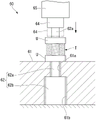
Fig. 11 is a schematic diagram showing an example of a test apparatus for compression resistance.
As shown in fig. 11, the compression resistance of the coil sheaths of examples 1 to 3 and comparative example 1 was evaluated using a sample T of 20mm in total length, both ends of which were fixed by crimp terminals U. Each crimp terminal U is provided within a range of 5mm from the end surface of the test sample T.
As the measured value of the compression resistance, the spring constant at the time of compression in the axial direction of the test specimen T was used.
The test apparatus 60 has a base 61, a guide pin 62, a pressing head 64, and a load cell 65. The test apparatus 60 further includes a control unit and a measurement value calculation device, which are not shown.
The pedestal 61 is a disk-shaped member having high rigidity. The base 61 has a through hole 61a and a hole 61b formed from the upper side toward the lower side in the thickness direction. The inner diameter of the through hole 61a is smaller than the inner diameter of the sample T. The hole 61b has a larger inner diameter than the through hole 61 a.
The guide pin 62 has a lever 62a and a pressing plate 62 b.
The rod 62a has an outer diameter that can be inserted through the through hole 61a and the sample T. The rod 62a is inserted through the through hole 61a from below and protrudes above the base 61.
The pressing plate 62b has an outer shape that can be inserted into the hole 61b and cannot be inserted into the through hole 61a, and is fixed to the lower end of the rod 62 a.
The upper end portion of the rod 62a is pressed downward, and can be moved on the base 61 from a state of protruding longer than the entire length of the sample T to a state of protruding shorter than the entire length of the sample T.
The pressing head 64 is connected to an elevating device, not shown, via a load cell 65. The pressing head 64 is disposed above the rod 62a so as to be able to move up and down.
The pressing head 64 presses the upper end of the sample T inserted into the rod 62a from above toward the pedestal 61. The pressing head 64 is provided with a hole into which the tip end portion of the rod 62a is inserted. Therefore, when the test sample T is pressed, the pressing load is not transmitted to the lever 62 a.
The load cell 65 measures a load applied to the pressing head 64.
The spring constant of the test sample T was measured by the test apparatus 60 as follows.
The sample T is inserted into the rod 62a protruding from the base 61, and the sample T is placed on the base 61.
Then, as indicated by the two-dot chain line, the pressing head 64 is lowered to compress the sample T placed on the base 61 in the axial direction. The magnitude of the load output from the load cell 65 at each lowered position of the pressing head 64 is obtained. The testing device 60 calculates the spring constant of the sample T under compression from the relationship between the lowered position and the magnitude of the load.
The unit of the spring constant is kN/mm.
[ evaluation results ]
As shown in { table 2}, the measured values of the rotation angles of the tips of examples 1 to 3 and comparative example 1 in the rotation transmissibility test were 8.94 degrees, 13.94 degrees, 30.58 degrees, and 0.00 degrees, respectively. The rotation transmissibility was judged to be good (a) in example 1, very good (a +) in examples 2 and 3, and poor (B) in comparative example 1. However, since the spring constant of example 3 is about 2.2 times that of example 2, example 3 is remarkably superior in rotation transmission property to example 2.
The reason why the rotation transmission performance of example 2 is superior to that of example 1 is considered to be that the width w of the flat wire coil 12 of example 1 is 2.5 times the diameter d of the circular wire coil 11, whereas in example 2, w is 2 times d.
In the rotation transmissibility test, the sample S draws a ring rotated by 360 degrees, and therefore when the base end side is rotated, the amount of bending and the direction of bending with respect to the sample S in the ring portion change as the amount of rotation increases. Therefore, the smaller the resistance of the sample S, the more bendable the sample S can be bent, the better the rotation transmission.
It is considered that if the width w of the rectangular wire coil 12 is 2 times or less the diameter d of the circular wire coil 11, the rectangular wire coil 12 is easily bent, and thus the rotation transmission performance is improved.
The reason why the rotation transmission performance of example 3 is superior to that of examples 1 and 2 is considered to be that the inner layer has a 2-layer structure of the circular wire coils 11 and 21 except that w/d is 2 times. The circular wire coils 11 and 21 having different winding directions are in point contact with each other, and therefore can smoothly slide relative to each other when bent. This reduces the resistance to bending.
In the case of comparative example 1, since the tip rotation angle was 0.00 degrees, the tip could not be rotated only by 45 degrees at the proximal end. This is considered to be because the circular wire coil 11 enters the gap of the flat wire coil 12 outside the bending during the bending, and the resistance when the coil is bent in the opposite direction becomes excessively large.
As shown in { Table 2}, the spring constants of examples 1 to 3 and comparative example 1 in the compression resistance test were measured to be 1.69kN/mm, 2.28kN/mm, and 0.85kN/mm, respectively. The compression resistance was judged to be good (A) in examples 1 to 3, and poor (B) in comparative example 1.
The spring constants of examples 1 and 2 were considered to be the same because the sectional areas were equal to each other, the materials were the same, and the close windability was also equal.
In contrast, comparative example 1 is similar to examples 1 and 2 in terms of the cross-sectional area and material, and therefore, it is considered that the reason why the spring constant is low is that the close wrapability is poor. That is, when the round wire coil 11 enters the gap in the flat wire coil 12, the winding direction becomes nonuniform, and a gap is generated between the windings adjacent to each other. The amount of depression of the pressing head 64 also includes an amount of depression for eliminating the gap between the windings, and therefore the spring constant is reduced.
The reason why the spring constant of example 3 is larger than that of examples 1 and 2 is considered that the cross-sectional area of the test sample T of example 3 is large.
While preferred embodiments and examples of the present invention have been described above, the present invention is not limited to these embodiments and examples. Addition, omission, replacement, and other changes in configuration may be made within the scope not departing from the spirit of the present invention.
The present invention is not limited to the above description, but is defined only by the appended claims.
Industrial applicability
According to the embodiments described above, it is possible to provide a medical coil having excellent rotation transmission characteristics even when the outer diameter is small, a method for manufacturing the medical coil, and a medical device having the medical coil and capable of improving operability.
Description of the symbols
5 operating shaft
10. 20 coil sheath (medical coil)
11. 21 round wire coil
12 flat wire coil
13. 14, U crimping terminal
15 core bar
50 holding pliers (medical equipment)
60. 70 test device
Inner Li, Li1 and Li2 layers
Outer layer of Lo
S, T test sample
S1, S2, S3 and S4 gaps
Wf Metal flat wire (Metal wire)
Wr Metal flat wire (Metal wire)
The claims (modification according to treaty clause 19)
(modified) a medical coil having a plurality of winding layers formed by winding a metal wire in a spiral shape, the plurality of winding layers forming a multilayer coil, wherein,
the medical coil includes:
an inner layer of metal round wire in the multilayer coil; and
an outer layer of the multilayer coil is composed of a metal flat wire,
the inner layer and the outer layer are contiguous to each other.
2. The medical coil according to claim 1,
the width of the flat metal wire is more than 1 time and less than 2 times of the diameter of the round metal wire.
3. The medical coil according to claim 1,
the multilayer coil includes:
2 inner layers each composed of the inner layer and arranged at different positions in a radial direction of the medical coil; and
the outer layer is disposed outside the 2 inner layers. The endoscopic balloon treatment instrument according to claim 1, wherein the distal end portion is larger than the tapered portion with respect to a width of the rib-like thick wall portion.
4. The medical coil according to claim 1,
the metal round wire and the metal flat wire are densely wound.
(modified) a method for manufacturing a medical coil, comprising the steps of:
a first step of winding a metal round wire around a core bar to form at least 1 layer of round wire coil; and
and a second step of forming a rectangular wire coil in contact with the outermost peripheral portion of the round wire coil by winding a rectangular metal wire around the outermost peripheral portion of the round wire coil.
6. The manufacturing method of medical coil according to claim 5,
the width of the flat metal wire is more than 1 time and less than 2 times of the outer diameter of the round metal wire.
7. The manufacturing method of medical coil according to claim 5,
in the first step, 2 layers of the circular wire coil are formed.
8. The manufacturing method of medical coil according to claim 5,
in the first and second steps, the round metal wire and the flat metal wire are densely wound.
9. A medical device comprising the medical coil according to claim 1.
Statement or declaration (modification according to treaty clause 19)
In claim 1, the "outer layer composed of flat metal wires in the multilayer coil" is changed to "the outer layer composed of flat metal wires in the multilayer coil, and the inner layer and the outer layer are contiguous to each other".
The modification of claim 1 is based on paragraphs 0034 and 0043 of the PCT international publication, without exceeding the scope of the original application.
By this modification, it is specified in claim 1 that "the inner layer and the outer layer are contiguous to each other".
In claim 5, "the rectangular wire coil is formed by winding the flat metal wire around the outermost periphery of the circular wire coil" is changed to "the rectangular wire coil is formed by winding the flat metal wire around the outermost periphery of the circular wire coil and is in contact with the outermost periphery of the circular wire coil".
The modification of claim 5 is based on paragraph 0043 of the PCT international publication without exceeding the scope of the original application.
By this modification, "the flat wire coil formed in contact with the outermost peripheral portion of the circular wire coil" is defined in claim 5.
Claims (9)
1. A medical coil having a plurality of winding layers formed by spirally winding a metal wire, the plurality of winding layers forming a multilayer coil, wherein,
the medical coil includes:
an inner layer of metal round wire in the multilayer coil; and
and the outer layer of the multilayer coil is composed of a metal flat wire.
2. The medical coil according to claim 1,
the width of the flat metal wire is more than 1 time and less than 2 times of the diameter of the round metal wire.
3. The medical coil according to claim 1,
the multilayer coil includes:
2 inner layers each composed of the inner layer and arranged at different positions in a radial direction of the medical coil; and
the outer layer is disposed outside the 2 inner layers.
4. The medical coil according to claim 1,
the metal round wire and the metal flat wire are densely wound.
5. A method for manufacturing a medical coil, comprising the steps of:
a first step of winding a metal round wire around a core bar to form at least 1 layer of round wire coil; and
and a second step of winding a flat metal wire around an outermost periphery of the round wire coil to form a flat wire coil.
6. The manufacturing method of medical coil according to claim 5,
the width of the flat metal wire is more than 1 time and less than 2 times of the outer diameter of the round metal wire.
7. The manufacturing method of medical coil according to claim 5,
in the first step, 2 layers of the circular wire coil are formed.
8. The manufacturing method of medical coil according to claim 5,
in the first step and the second step, the round metal wire and the flat metal wire are densely wound.
9. A medical device comprising the medical coil according to claim 1.
Applications Claiming Priority (1)
| Application Number | Priority Date | Filing Date | Title |
|---|---|---|---|
| PCT/JP2020/020000 WO2021234874A1 (en) | 2020-05-20 | 2020-05-20 | Medical coil, manufacturing method therefor, and medical equipment |
Publications (1)
| Publication Number | Publication Date |
|---|---|
| CN114667106A true CN114667106A (en) | 2022-06-24 |
Family
ID=78708287
Family Applications (1)
| Application Number | Title | Priority Date | Filing Date |
|---|---|---|---|
| CN202080078266.1A Pending CN114667106A (en) | 2020-05-20 | 2020-05-20 | Medical coil, method for producing same, and medical device |
Country Status (4)
| Country | Link |
|---|---|
| US (1) | US20230030901A1 (en) |
| JP (1) | JPWO2021234874A1 (en) |
| CN (1) | CN114667106A (en) |
| WO (1) | WO2021234874A1 (en) |
Cited By (1)
| Publication number | Priority date | Publication date | Assignee | Title |
|---|---|---|---|---|
| CN116525286A (en) * | 2023-07-04 | 2023-08-01 | 通友微电(四川)有限公司 | Compact winding inductor and preparation method thereof |
Families Citing this family (1)
| Publication number | Priority date | Publication date | Assignee | Title |
|---|---|---|---|---|
| USD1022196S1 (en) * | 2020-07-07 | 2024-04-09 | Olympus Corporation | Operating unit of treatment tool for endoscope |
Family Cites Families (3)
| Publication number | Priority date | Publication date | Assignee | Title |
|---|---|---|---|---|
| JP2007260248A (en) * | 2006-03-29 | 2007-10-11 | Fujinon Corp | Treatment implement for endoscope |
| EP2446802B1 (en) * | 2010-01-29 | 2013-02-13 | Olympus Medical Systems Corp. | Insertion instrument, endoscope |
| JP2016016299A (en) * | 2014-07-11 | 2016-02-01 | 朝日インテック株式会社 | Coil body, and medical instrument having coil body |
-
2020
- 2020-05-20 JP JP2022524773A patent/JPWO2021234874A1/ja active Pending
- 2020-05-20 WO PCT/JP2020/020000 patent/WO2021234874A1/en active Application Filing
- 2020-05-20 CN CN202080078266.1A patent/CN114667106A/en active Pending
-
2022
- 2022-09-30 US US17/957,126 patent/US20230030901A1/en active Pending
Cited By (2)
| Publication number | Priority date | Publication date | Assignee | Title |
|---|---|---|---|---|
| CN116525286A (en) * | 2023-07-04 | 2023-08-01 | 通友微电(四川)有限公司 | Compact winding inductor and preparation method thereof |
| CN116525286B (en) * | 2023-07-04 | 2023-09-19 | 通友微电(四川)有限公司 | Compact winding inductor and preparation method thereof |
Also Published As
| Publication number | Publication date |
|---|---|
| WO2021234874A1 (en) | 2021-11-25 |
| US20230030901A1 (en) | 2023-02-02 |
| JPWO2021234874A1 (en) | 2021-11-25 |
Similar Documents
| Publication | Publication Date | Title |
|---|---|---|
| US20230030901A1 (en) | Medical coil, method for manufacturing the same, and medical device | |
| JP4889062B2 (en) | Guide wire | |
| WO2017090473A1 (en) | Connection structure and connection method | |
| US6743185B2 (en) | Handle assembly for surgical instrument and method of making the assembly | |
| EP1927312A1 (en) | Endoscope insertion part | |
| EP2612608B1 (en) | Medical coil, method of manufacturing same, and medical apparatus | |
| JP2012034922A (en) | Guide wire | |
| EP1087706A1 (en) | Snap handle assembly for an endoscopic instrument | |
| EP2074927B1 (en) | Endoscope | |
| US20180207407A1 (en) | Guide wire and manufacturing method of guide wire | |
| CN102281826A (en) | Treatment device for endoscope | |
| US20160346518A1 (en) | Medical guide wire | |
| US7534253B2 (en) | Clevis assemblies for medical instruments and methods of manufacture of same | |
| US9468451B2 (en) | Medical guide wire | |
| EP2327367A1 (en) | Instrument for endoscopic treatment | |
| US20210299402A1 (en) | Catheter tube and method for manufacturing the same | |
| CN113523049B (en) | Bent pipe manufacturing device and bent pipe manufacturing method | |
| JP2015070895A (en) | Shaft and guide wire using the shaft | |
| JP6730482B1 (en) | Single wire for medical treatment instrument and medical treatment instrument | |
| JP7051032B1 (en) | Guide wire | |
| CN117136085A (en) | Medical wire and guide wire | |
| JP4608518B2 (en) | Tubular member and endoscope treatment tool | |
| EP1985329A1 (en) | Tubular member and endoscopic instrument | |
| US20240082550A1 (en) | Guide wire | |
| US20220296860A1 (en) | Guide wires |
Legal Events
| Date | Code | Title | Description |
|---|---|---|---|
| PB01 | Publication | ||
| PB01 | Publication | ||
| SE01 | Entry into force of request for substantive examination | ||
| SE01 | Entry into force of request for substantive examination |