CN114660552B - Satellite-borne GNSS-S radar ship target signal receiving and direct interference suppression method - Google Patents
Satellite-borne GNSS-S radar ship target signal receiving and direct interference suppression method Download PDFInfo
- Publication number
- CN114660552B CN114660552B CN202210204507.3A CN202210204507A CN114660552B CN 114660552 B CN114660552 B CN 114660552B CN 202210204507 A CN202210204507 A CN 202210204507A CN 114660552 B CN114660552 B CN 114660552B
- Authority
- CN
- China
- Prior art keywords
- antenna
- direct interference
- subarray
- digital
- gnss
- Prior art date
- Legal status (The legal status is an assumption and is not a legal conclusion. Google has not performed a legal analysis and makes no representation as to the accuracy of the status listed.)
- Active
Links
- 230000001629 suppression Effects 0.000 title claims abstract description 52
- 238000000034 method Methods 0.000 title claims abstract description 24
- 238000005457 optimization Methods 0.000 claims description 41
- 238000001514 detection method Methods 0.000 claims description 20
- 230000002068 genetic effect Effects 0.000 claims description 19
- 238000010586 diagram Methods 0.000 claims description 13
- 230000003321 amplification Effects 0.000 claims description 6
- 238000009434 installation Methods 0.000 claims description 6
- 238000003199 nucleic acid amplification method Methods 0.000 claims description 6
- 230000010287 polarization Effects 0.000 claims description 6
- 230000001678 irradiating effect Effects 0.000 claims description 5
- 230000015572 biosynthetic process Effects 0.000 claims description 3
- 238000006243 chemical reaction Methods 0.000 claims description 3
- 238000001914 filtration Methods 0.000 claims description 3
- 238000002921 genetic algorithm search Methods 0.000 claims description 3
- 238000013139 quantization Methods 0.000 claims description 3
- 238000005070 sampling Methods 0.000 claims description 3
- 238000003786 synthesis reaction Methods 0.000 claims description 2
- 238000003384 imaging method Methods 0.000 description 6
- 230000004048 modification Effects 0.000 description 2
- 238000012986 modification Methods 0.000 description 2
- 238000011160 research Methods 0.000 description 2
- 239000000523 sample Substances 0.000 description 2
- 238000003491 array Methods 0.000 description 1
- 230000006872 improvement Effects 0.000 description 1
- 230000003287 optical effect Effects 0.000 description 1
- 230000008569 process Effects 0.000 description 1
- 238000012545 processing Methods 0.000 description 1
- 230000005855 radiation Effects 0.000 description 1
- 230000035945 sensitivity Effects 0.000 description 1
- 238000012360 testing method Methods 0.000 description 1
Images


Classifications
-
- G—PHYSICS
- G01—MEASURING; TESTING
- G01S—RADIO DIRECTION-FINDING; RADIO NAVIGATION; DETERMINING DISTANCE OR VELOCITY BY USE OF RADIO WAVES; LOCATING OR PRESENCE-DETECTING BY USE OF THE REFLECTION OR RERADIATION OF RADIO WAVES; ANALOGOUS ARRANGEMENTS USING OTHER WAVES
- G01S7/00—Details of systems according to groups G01S13/00, G01S15/00, G01S17/00
- G01S7/02—Details of systems according to groups G01S13/00, G01S15/00, G01S17/00 of systems according to group G01S13/00
- G01S7/36—Means for anti-jamming, e.g. ECCM, i.e. electronic counter-counter measures
-
- G—PHYSICS
- G01—MEASURING; TESTING
- G01S—RADIO DIRECTION-FINDING; RADIO NAVIGATION; DETERMINING DISTANCE OR VELOCITY BY USE OF RADIO WAVES; LOCATING OR PRESENCE-DETECTING BY USE OF THE REFLECTION OR RERADIATION OF RADIO WAVES; ANALOGOUS ARRANGEMENTS USING OTHER WAVES
- G01S13/00—Systems using the reflection or reradiation of radio waves, e.g. radar systems; Analogous systems using reflection or reradiation of waves whose nature or wavelength is irrelevant or unspecified
- G01S13/88—Radar or analogous systems specially adapted for specific applications
- G01S13/89—Radar or analogous systems specially adapted for specific applications for mapping or imaging
- G01S13/90—Radar or analogous systems specially adapted for specific applications for mapping or imaging using synthetic aperture techniques, e.g. synthetic aperture radar [SAR] techniques
- G01S13/9004—SAR image acquisition techniques
-
- G—PHYSICS
- G01—MEASURING; TESTING
- G01S—RADIO DIRECTION-FINDING; RADIO NAVIGATION; DETERMINING DISTANCE OR VELOCITY BY USE OF RADIO WAVES; LOCATING OR PRESENCE-DETECTING BY USE OF THE REFLECTION OR RERADIATION OF RADIO WAVES; ANALOGOUS ARRANGEMENTS USING OTHER WAVES
- G01S13/00—Systems using the reflection or reradiation of radio waves, e.g. radar systems; Analogous systems using reflection or reradiation of waves whose nature or wavelength is irrelevant or unspecified
- G01S13/88—Radar or analogous systems specially adapted for specific applications
- G01S13/89—Radar or analogous systems specially adapted for specific applications for mapping or imaging
- G01S13/90—Radar or analogous systems specially adapted for specific applications for mapping or imaging using synthetic aperture techniques, e.g. synthetic aperture radar [SAR] techniques
- G01S13/9021—SAR image post-processing techniques
-
- G—PHYSICS
- G01—MEASURING; TESTING
- G01S—RADIO DIRECTION-FINDING; RADIO NAVIGATION; DETERMINING DISTANCE OR VELOCITY BY USE OF RADIO WAVES; LOCATING OR PRESENCE-DETECTING BY USE OF THE REFLECTION OR RERADIATION OF RADIO WAVES; ANALOGOUS ARRANGEMENTS USING OTHER WAVES
- G01S19/00—Satellite radio beacon positioning systems; Determining position, velocity or attitude using signals transmitted by such systems
- G01S19/01—Satellite radio beacon positioning systems transmitting time-stamped messages, e.g. GPS [Global Positioning System], GLONASS [Global Orbiting Navigation Satellite System] or GALILEO
- G01S19/13—Receivers
- G01S19/14—Receivers specially adapted for specific applications
-
- G—PHYSICS
- G01—MEASURING; TESTING
- G01S—RADIO DIRECTION-FINDING; RADIO NAVIGATION; DETERMINING DISTANCE OR VELOCITY BY USE OF RADIO WAVES; LOCATING OR PRESENCE-DETECTING BY USE OF THE REFLECTION OR RERADIATION OF RADIO WAVES; ANALOGOUS ARRANGEMENTS USING OTHER WAVES
- G01S19/00—Satellite radio beacon positioning systems; Determining position, velocity or attitude using signals transmitted by such systems
- G01S19/01—Satellite radio beacon positioning systems transmitting time-stamped messages, e.g. GPS [Global Positioning System], GLONASS [Global Orbiting Navigation Satellite System] or GALILEO
- G01S19/13—Receivers
- G01S19/35—Constructional details or hardware or software details of the signal processing chain
- G01S19/37—Hardware or software details of the signal processing chain
Landscapes
- Engineering & Computer Science (AREA)
- Remote Sensing (AREA)
- Radar, Positioning & Navigation (AREA)
- Physics & Mathematics (AREA)
- Computer Networks & Wireless Communication (AREA)
- General Physics & Mathematics (AREA)
- Electromagnetism (AREA)
- Signal Processing (AREA)
- Radar Systems Or Details Thereof (AREA)
- Variable-Direction Aerials And Aerial Arrays (AREA)
Abstract
The invention relates to a satellite-borne GNSS-S radar ship target signal receiving and direct interference suppression method, which comprises the following steps: a. optimizing the antenna; b. optimizing the suppression of the direct interference signal; c. digital beamforming is performed on the GNSS-S signals. The invention can receive weak scattering signals of large-range sea surface ship targets and inhibit direct interference signals of multiple navigation satellites.
Description
Technical Field
The invention relates to a satellite-borne GNSS-S radar ship target signal receiving and direct interference suppression method.
Background
The detection of a large-area sea surface ship target is always a hot point of scientific research, is influenced by weather such as sea cloud, rain, fog and the like, an optical sensor is difficult to exert the advantages of high-resolution imaging and identification in the detection, and a satellite-borne SAR system can penetrate through clouds and fog, has the characteristic of all-weather sea observation all day long, and is suitable for the high-resolution imaging and detection application of the sea surface ship target. However, the existing satellite-borne SAR system is difficult to realize long-time tracking of a ship target, and the existing technology usually adopts a mode of actively transmitting a high-power signal, so that the system is easy to intercept and interfere.
In this regard, some techniques utilize the reflected signal (GNSS-R) of the navigation satellite signal to complete the sea surface wind field survey and implement low earth orbit satellite loading tests. Meanwhile, the technology also provides that satellite-to-ground double-station SAR imaging is realized on the ground by using a scattering signal (GNSS-S) of a navigation satellite signal, but the imaging resolution is generally more than 10m due to the limitation of the effective bandwidth of the navigation satellite signal, so that meter-level resolution SAR imaging is difficult to realize and image domain ship target identification is not facilitated.
The satellite-borne GNSS-S radar can receive ship target scattering signals of navigation satellite signals, can realize ship target detection after signal processing, does not need to actively transmit high-power signals, has the advantages of low power consumption, light weight and the like, or becomes one of important technical means for space detection of sea surface ships. However, the power of the navigation satellite signal is low, and after the two-way attenuation, the power of the ship target scattering signal is far lower than the noise power. In addition, because the number of the on-orbit navigation satellites is large, part of navigation satellite signals directly enter the satellite-borne GNSS-S radar antenna to become direct interference signals, and the power of the direct interference signals is generally 30-50dB greater than that of the scattered signals of the ship targets. Therefore, it is desirable to find a technology for receiving signals and suppressing direct interference signals of a large-scale sea-surface ship target to improve the detection performance of the large-scale sea-surface ship target.
Disclosure of Invention
The invention aims to provide a method for receiving a target signal and suppressing direct interference of a satellite-borne GNSS-S radar ship.
In order to achieve the above object, the present invention provides a method for suppressing target signal reception and direct interference of a satellite-borne GNSS-S radar ship, comprising the steps of:
a. optimizing an antenna;
b. optimizing the suppression of the direct interference signal;
c. digital beamforming is performed on the GNSS-S signals.
According to one aspect of the invention, the satellite-borne GNSS-S radar antenna is a non-uniform sub-array type multi-channel antenna, and comprises:
m multiplied by N non-uniform subarray antennas for receiving scattered signals of large-area sea surface ship targets by wide beams, wherein the array element number of each subarray antenna is K m,n Taking 3-10, the offset of the distance to the nth array element position relative to the distance to the 1 st array element position is d n ;
The digital receiving assembly is used for carrying out low-noise amplification, band-pass filtering, down-conversion, intermediate frequency amplification and intermediate frequency signal sampling quantization on the GNSS-S signals output by the non-uniform subarray antenna to obtain digital domain intermediate frequency GNSS-S signals, and recording the position of the digital domain intermediate frequency GNSS-S signals to be S in the mth direction and the distance of the digital domain intermediate frequency GNSS-S signals to be n in the nth direction m,n (t), t is a fast time variable.
According to an aspect of the present invention, in the step (a), the non-uniform subarray arrangement of the non-uniform subarray type multi-channel antenna and the number of array elements of the subarray antenna are optimized, including:
a1, establishing a non-uniform subarray antenna optimization multi-objective function according to an antenna scanning range, total antenna gain, subarray antenna gain, main antenna lobe width and antenna side lobe level, and searching and optimizing array element numbers of each subarray antenna to enable a whole antenna directional diagram to meet the requirements of maximum total gain, minimum main antenna lobe width and minimum antenna side lobe level;
and a2, searching and optimizing variables of the non-uniform subarray antenna optimization multi-objective function by using a parallel genetic algorithm to obtain an optimal arrangement mode of the non-uniform subarray type multi-channel antenna, an array element number of the subarray antenna and an optimal complex weight corresponding to each subarray antenna.
According to one aspect of the invention, the antenna scans over a range of azimuth directions of In the range of the distance direction scanning range theta epsilon-theta max ,θ max ],
 Taking 3-6 degrees, theta max Taking 20-30 degrees;
the total gain G of the antenna is more than or equal to G 0 The gain GS of the subarray antenna is more than or equal to GS 0 ,G 0 Taking GS as 30dB-45dB 0 Taking 10dB-20dB;
the width phi of the main lobe of the antenna in the azimuth direction is less than or equal to phi 0 The width theta of the main lobe of the antenna in the distance direction is not more than theta 0 ,Φ 0 1 to 2 degrees are taken and theta is 0 Taking 3-6 degrees;
when the antenna beam center points Time, antenna pattern
 Side lobe level of
 P 0 Taking-13 dB to-18 dB;
the non-uniform subarray antenna optimization multi-objective function is as follows:

the objective function after weighted combination is:
f(K m,n ,d n ,A m,n ,a m,n )=-w 1 ·f 1 +w 2 ·f 2 +w 3 ·f 3 +w 4 ·f 4 ;
wherein, and w 1 ∈[0.2,0.3],w 2 ∈[0.1,0.2],w 3 ∈[0.1,0.2],w 4 ∈[0.5,0.8](ii) a The variable of the multi-objective function optimization is K m,n 、d n 、A m,n 、a m,n ;K m,n The number of antenna elements of the m-th sub-array antenna in azimuth direction and the n-th sub-array antenna in distance direction, and K m,n ∈[3,10];d n Is the distance offset of the nth range sub-array along the azimuth direction, and d n ∈[0,10λ c ],λ c The wavelength is corresponding to the working center frequency; a. The m,n And a m,n The amplitude values and the phase values of the mth azimuth direction sub-array antenna and the nth distance sub-array antenna are respectively obtained; p is SL (. H) is a function of the maximum sidelobe level of the antenna pattern;
weighting and combining the target function f (K) by utilizing a parallel genetic algorithm m,n ,d n ,A m,n ,a m,n ) Search optimization is carried out to obtain the optimal value opt { K of the multi-objective function variable m,n }、opt{d n }、opt{A m,n }、opt{a m,n Obtaining the array element number opt { K } of each subarray antenna m,n An offset opt from the direction of distance d n And completing non-uniform sub-array type multi-channel antenna arrangement.
According to an aspect of the invention, in the step (b), the non-uniform subarray type multi-channel antenna is optimized, and the direct interference signals of multiple navigation satellites are deeply suppressed.
According to an aspect of the present invention, the step (b) comprises:
b1, establishing a multi-objective function for suppressing and optimizing direct interference signals, and realizing suppression depth maximization on the direct interference signals of the P navigation satellites, so that the whole antenna directional diagram meets the requirements of maximum total gain, minimum antenna main lobe width and minimum antenna side lobe level;
and b2, searching and optimizing the multi-objective function for the direct interference signal suppression optimization by using a parallel genetic algorithm to obtain the optimal complex weight of each subarray antenna, and realizing the deep suppression of P direct interference signals.
According to one aspect of the invention, the angles of the direct interference signals of a plurality of navigation satellites are calculated according to the position and the speed of the plurality of navigation satellites, the position and the speed of the satellite-borne GNSS-S radar, the antenna installation angle, the detection area and other information, and the angle of the direct interference signal of the pth navigation satellite is calculated by taking the normal direction of the antenna as reference
Calculating the direct interference signal power of a plurality of navigation satellites according to the positions and the speeds of the plurality of navigation satellites, the positions and the speeds of the satellite-borne GNSS-S radar and the antenna installation angle, and calculating the direct interference signal power Ps of the pth navigation satellite p ;
According to the double-station radar equation, calculating the echo power Pt of the satellite-borne GNSS-S radar to the minimum detectable ship target min The power of the direct interference signal with each navigation satellite meets Pt min ≥Ps p -Gy p P =1, 2.. P, wherein, gy p The suppression depth of the antenna to the direct interference signal of the p navigation satellite; p is the total number of navigation satellites of the direct interference signal;
the suppression width of the direct interference signal of the p-th navigation satellite meets delta phi in the azimuth direction p ∈[Φ 0 ,2Φ 0 ]Satisfies Δ Θ in the distance direction p ∈[Θ 0 ,2Θ 0 ];
Optimizing the weighted amplitude A1 of each antenna subarray search m,n And phase a1 m,n Maximizing the suppression depth of the P direct interference signals of the navigation satellite, and enabling the whole antenna directional diagram to meet the conditions of maximum total gain, minimum antenna main lobe width and minimum antenna side lobe level, wherein the direct interference signal suppression optimization multi-objective function is as follows:

the objective function after weighted combination is:
g(A1 m,n ,a1 m,n )=-γ 1 ·g 1 +γ 2 ·g 2 +γ 3 ·g 3 +γ 4 ·g 4 -γ 5 ·g 5 ;
wherein, and gamma is 1 ∈[0.2,0.3],γ 2 ∈[0.1,0.2],γ 3 ∈[0.1,0.2],γ 4 ∈[0.35,0.5],γ 5 ∈[0.35,0.5];
Weighting the combined target function g (A1) by using a parallel genetic algorithm m,n ,a1 m,n ) Searching and optimizing to obtain the optimal value opt { A1) of the multi-objective function variable m,n H and opt { a1 } m,n The signals s output by the M multiplied by N sub-array antennas of the antenna are multiplied m,n (t) performing complex weighting to realize digital beam synthesis
 Forming an echo signal for the digital beam; e is the base number of the natural logarithm function;
and adjusting the pointing angle of the beam center for the detection areas pointed by different beams, repeatedly searching and optimizing the direct interference signal suppression optimization multi-objective function by utilizing a parallel genetic algorithm, obtaining the optimized complex weights pointed by different beams, and realizing the depth suppression of the direct interference signals of the P navigation satellites during the large-range sea surface ship target detection.
According to an aspect of the present invention, in the step (c), performing digital beamforming on the mxn GNSS-S signals output by the non-uniform subarray type multi-channel antenna by using an optimized digital beamformer to obtain high signal-to-noise ratio GNSS-S signals.
According to one aspect of the invention, an optimized digital beamformer comprises:
n azimuth digital beam formers for performing azimuth complex weighting on the digital domain intermediate frequency GNSS-S signals output from each row, wherein the output of the nth azimuth digital beam former is
A range-wise digital beamformer for complex weighting of range-wise GNSS-S signals M × N plural weights A1 m,n 、a1 m,n Obtaining an optimal value opt { A1 ] through multi-objective function modeling and genetic algorithm search optimization m,n }、opt{a1 m,n And realizing deep suppression of direct interference signals of a plurality of navigation satellites, wherein,
 forming the output echo signal for the nth azimuth digital beam.
According to one aspect of the invention, the non-uniform subarray type multi-channel antenna adopts a non-uniform subarray type phased array antenna technology in the azimuth direction, and adopts a full digital array antenna technology in the distance direction;
the non-uniform sub-array type multi-channel antenna works in a front side view mode, M sub-array antennas and N array elements which are respectively arranged in the azimuth direction and the distance direction correspond to M multiplied by N receiving channels, and each receiving channel is a wide wave beam;
the working frequency range of the non-uniform sub-array type multi-channel antenna is 1.17GHz-1.29GHz, the polarization mode is left-hand circular polarization, and the total gain of the antenna is more than 30dB;
irradiating the sea surface of a large area by Q navigation satellites as a scattering source, and directly irradiating by P navigation satellite signals as an interference source;
the included angle between the incident angle of the direct interference signal of the pth navigation satellite and the incident angle of the antenna beam center is thetas p The pth navigation satelliteThe distance between the satellite interference source and the satellite-borne GNSS-S radar antenna is Rt p The power arriving at the antenna is Ps p ;
The included angle between the azimuth angle of the direct interference signal of the p navigation satellite and the central azimuth angle of the antenna wave beam is The azimuth angle of the antenna beam center is 0 degree;
utilizing digital beam forming to carry out beam forming on GNSS-S signals output by M multiplied by N channels to obtain K digital sub-beams, wherein the corresponding width of the K digital sub-beam is W k The total width of the probe is
After the digital wave beam is formed, the antenna main lobe presents a narrow wave beam in the azimuth direction and the distance direction, and a plurality of digital sub-wave beams are formed in the distance direction, so that the scattered signal receiving of the large-area sea surface ship target is realized.
According to the concept of the invention, a large-area ship signal receiving and direct interference suppression method of the satellite-borne GNSS-S radar is provided, so that weak scattering signals of ship targets on a large sea surface can be received, and direct interference signals of a plurality of navigation satellites can be suppressed.
According to one scheme of the invention, the satellite-borne GNSS-S radar adopts the non-uniform subarray type multi-channel antenna to synchronously receive weak scattering signals of large-range sea surface ship targets, establishes a non-uniform subarray antenna optimization multi-objective function according to the requirements of an antenna scanning range, antenna total gain, subarray antenna gain, beam secondary lobe level and the like, and searches and optimizes the multi-objective function by utilizing a genetic algorithm to obtain the non-uniform subarray type multi-channel antenna arrangement and each subarray element number. In addition, according to the position and the speed of a plurality of navigation satellites, the position and the speed of a satellite-borne GNSS-S radar, the antenna installation angle, the detection area and other information, the angles and the powers of direct interference signals of the plurality of navigation satellites are calculated, a direct interference signal suppression optimization multi-objective function is established, the complex weights of non-uniform sub-arrays are searched and optimized by using a genetic algorithm, the direct interference signals of the navigation satellites at a plurality of angles are deeply suppressed, the signal-to-noise ratio of a target scattering signal of a sea surface ship is improved, and the optimized digital beam forming is realized. Therefore, the method has the advantages of large receiving range, high sensitivity, small number of subarrays, high interference rejection ratio and the like, can carry out deep rejection on the direct interference signals of a plurality of navigation satellites so as to improve the signal-to-noise ratio of the scattering signals of the sea surface ship targets, and has high application value and wide market application prospect.
According to one scheme of the invention, a non-uniform subarray type multi-channel antenna optimization technology is adopted, the number of receiving channels of the antenna is greatly reduced under the condition that the requirement of azimuth beam scanning performance is guaranteed, the complexity of a satellite-borne GNSS-S radar system is simplified, and the method has the advantages of few receiving channels, low system complexity, low power consumption and the like, and is suitable for target detection of sea surface ships in large areas and suppression application of space direct interference signals.
Drawings
FIG. 1 is a flow chart of a method for optimizing an antenna and suppressing direct interference of a satellite-borne GNSS-S radar according to an embodiment of the present invention;
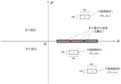
FIG. 2 is a diagram schematically illustrating a non-uniform sub-array type multi-channel antenna of a satellite-borne GNSS-S radar according to an embodiment of the present invention;
FIG. 3 is a schematic diagram of a target detection scene of a satellite-borne GNSS-S radar on a large-scale sea surface ship according to an embodiment of the present invention;
fig. 4 is a schematic diagram illustrating an incident angle of a pth direct interference signal with respect to a center of an antenna beam according to an embodiment of the present invention;
fig. 5 is a schematic view of the azimuth of the pth direct interference signal with respect to the center of the antenna beam according to an embodiment of the present invention;
fig. 6 is a schematic diagram illustrating an angular distribution of a non-uniform subarray antenna to P direct interference rejection areas according to an embodiment of the present invention.
Detailed Description
In order to more clearly illustrate the embodiments of the present invention or the technical solutions in the prior art, the drawings used in the embodiments will be briefly described below. It is obvious that the drawings in the following description are only some embodiments of the invention, and that for a person skilled in the art, other drawings can also be derived from them without inventive effort.
The present invention is described in detail below with reference to the drawings and the specific embodiments, which are not repeated herein, but the embodiments of the present invention are not limited to the following embodiments.
Referring to fig. 1, the method for receiving a large-area (large-range) sea-surface ship target signal and suppressing direct interference of a navigation satellite (i.e., direct interference signal suppression) of the space-borne GNSS-S radar can be applied to the research of a space-based distributed high-resolution wide-range SAR imaging system, and can be used in a space-borne radar system to realize large-range ship target detection and space direct interference signal suppression. The method comprises the steps of firstly optimizing non-uniform subarray antennas 10, namely optimizing the non-uniform subarray antennas of the satellite-borne GNSS-S radar, wherein the non-uniform subarray configuration, the array elements of the subarray antennas and the like are optimized, and the number of the subarray antennas is reduced as much as possible under the condition that the beam performance of the antennas is guaranteed. Then, the direct interference signal rejection optimization 30 is performed, that is, the non-uniform sub-array type multi-channel antenna 20 is optimized, and the multiple navigation satellite direct interference signal rejection is optimized, so that the deep rejection is realized. Finally, digital beam forming is carried out on the MxN GNSS-S signals output by the non-uniform subarray type multi-channel antenna 20 by utilizing an optimized digital beam forming device 40, and GNSS-S signals with high signal-to-clutter ratios are obtained.
The non-uniform subarray antenna optimization 10 includes: an antenna beam multi-objective function model is built 101, namely a non-uniform subarray antenna optimization multi-objective function is built according to the requirements of an antenna scanning range, total antenna gain, subarray antenna gain, antenna main lobe width, antenna side lobe level and the like, and a plurality of variables such as array element number of each subarray antenna are searched and optimized, so that the whole antenna directional diagram meets the requirements of maximum total gain, minimum antenna main lobe width and minimum antenna side lobe level; and (4) optimizing A102 by using a parallel genetic algorithm, namely searching and optimizing variables of the non-uniform subarray antenna optimization multi-objective function by using the genetic algorithm to obtain the optimal arrangement mode of the non-uniform subarray type multi-channel antenna 20, the array element number of each non-uniform subarray antenna and the optimal complex weight corresponding to each subarray antenna.
In the specific process of optimizing multi-objective function modeling and searching optimization of the non-uniform subarray antenna, the scanning range of the antenna in the azimuth direction is In the range of the distance direction scanning, theta epsilon-theta max ,θ max ],
 Taking 3-6 degrees, theta max Taking 20-30 degrees; the total gain of the antenna is G ≥ G 0 The gain of the subarray antenna is GS or more 0 ,G 0 Taking GS as 30dB-45dB 0 Taking 10dB-20dB; the width of the main lobe of the antenna in the azimuth direction is phi or less 0 The width of the main lobe of the antenna in the distance direction is theta or less 0 ,Φ 0 Taking 1-2 degrees, theta 0 Taking 3-6 degrees; when the antenna beam center points
 Time, antenna pattern
 Side lobe level of
 P 0 Take-13 dB to-18 dB.
The non-uniform subarray antenna optimization multi-objective function is as follows:

the objective function after weighted combination is:
f(K m,n ,d n ,A m,n ,a m,n )=-w 1 ·f 1 +w 2 ·f 2 +w 3 ·f 3 +w 4 ·f 4 ;
wherein, and w 1 ∈[0.2,0.3],w 2 ∈[0.1,0.2],w 3 ∈[0.1,0.2],w 4 ∈[0.5,0.8](ii) a Making the antenna side lobe level minimization function larger; the variable of the multi-objective function optimization is K m,n 、d n 、A m,n 、a m,n ;K m,n The number of antenna elements of the m-th sub-array antenna in azimuth direction and the n-th sub-array antenna in distance direction, and K m,n ∈[3,10];d n Is the distance offset of the nth range subarray along the azimuth direction, and d n ∈[0,10λ c ],λ c The wavelength is corresponding to the working center frequency; a. The m,n And a m,n Amplitude values and phase values of the mth sub-array antenna in the azimuth direction and the nth sub-array antenna in the distance direction are respectively obtained; p is SL (. H) is a function of the maximum sidelobe level of the antenna pattern;
weighting the combined target function f (K) by using a parallel genetic algorithm m,n ,d n ,A m,n ,a m,n ) Search optimization is carried out to obtain the optimal value opt { K of the multi-objective function variable m,n }、opt{d n }、opt{A m,n }、opt{a m,n Obtaining the array element number opt { K } of each subarray antenna m,n An offset opt from the range direction { d } n And completing the non-uniform sub-array type multi-channel antenna 20 arrangement.
The direct interference signal rejection optimization 30 includes: constructing 301 an interference null multi-objective function model, namely establishing a direct interference signal suppression optimization multi-objective function, and realizing suppression depth maximization on the direct interference signals of the P navigation satellites, so that the whole antenna directional diagram meets the requirements of maximum total gain, minimum antenna main lobe width and minimum antenna side lobe level; and B302 is optimized by a parallel genetic algorithm, namely, the multi-objective function for the suppression optimization of the direct interference signals is searched and optimized to obtain the optimal complex weight of each subarray antenna, so that the deep suppression of P direct interference signals is realized.
In the specific direct interference signal suppression optimization multi-objective function modeling and search optimization, a plurality of direct interference signal suppression optimization multi-objective functions are usedThe method comprises the steps of calculating the angles of direct interference signals of a plurality of navigation satellites according to information such as the positions and the speeds of the navigation satellites, the positions and the speeds of satellite-borne GNSS-S radars, the installation angles of antennas and the like, causing direct interference by signals of P navigation satellites when detecting a ship on the sea surface, and calculating the angle of the direct interference signal of the P navigation satellite by taking the normal direction of the antenna as reference
Calculating the power of direct interference signals of a plurality of navigation satellites according to the position and speed of the plurality of navigation satellites, the position and speed of a satellite-borne GNSS-S radar, the antenna installation angle and other information, and calculating the power Ps of the direct interference signals of the pth navigation satellite p 。
According to the double-station radar equation, calculating the echo power Pt of the satellite-borne GNSS-S radar to the minimum detectable ship target min And the power of the direct interference signal with each navigation satellite meets Pt min ≥Ps p -Gy p P =1, 2.. P, wherein, gy p The suppression depth of the antenna to the direct interference signal of the p navigation satellite; p is the total number of navigational satellites in the direct interference signal. The suppression width of the direct interference signal of the p-th navigation satellite meets delta phi in the azimuth direction p ∈[Φ 0 ,2Φ 0 ]In the direction of distance, Δ Θ is satisfied p ∈[Θ 0 ,2Θ 0 ]。
Optimizing the weighted amplitude A1 of each antenna subarray search m,n (optimized amplitude) and phase a1 m,n And maximizing the suppression depth of the direct interference signals of the P navigation satellites, and enabling the whole antenna directional diagram to meet the conditions of maximum total gain, minimum width of a main lobe of the antenna and minimum level of a side lobe of the antenna, wherein the direct interference signal suppression optimization multi-objective function is as follows:

the objective function after weighted combination is:
g(A1 m,n ,a1 m,n )=-γ 1 ·g 1 +γ 2 ·g 2 +γ 3 ·g 3 +γ 4 ·g 4 -γ 5 ·g 5 ;
wherein, and gamma is 1 ∈[0.2,0.3],γ 2 ∈[0.1,0.2],γ 3 ∈[0.1,0.2],γ 4 ∈[0.35,0.5],γ 5 ∈[0.35,0.5];
The antenna side lobe level minimizing function is more proportional to the direct interference signal suppression depth maximizing function.
Weighting the combined target function g (A1) by using a parallel genetic algorithm m,n ,a1 m,n ) Search optimization is carried out to obtain the optimal value opt { A1 of the multi-objective function variable m,n }、opt{a1 m,n }, signal s output by M × N sub-array antennas of the antenna m,n (t) performing complex weighting to realize digital beam forming,
 forming an echo signal for the digital beam; e is the base number of the natural logarithm function;
 thereby suppressing the power of the direct interference signal of P navigation satellites.
And adjusting the pointing angle of the beam center for the detection areas pointed by different beams, and repeatedly searching and optimizing the direct interference signal suppression optimization multi-objective function by using a parallel genetic algorithm to obtain optimized complex weights pointed by different beams, thereby realizing the deep suppression of the direct interference signals of P navigation satellites during the large-range sea surface ship target detection.
Referring to fig. 2, the non-uniform sub-array type multi-channel antenna 20 includes: m multiplied by N non-uniform subarray antennas 201 for receiving scattering signals of large-area sea surface ship targets with wide beams to realize large-area sea surfaceNaval vessel target detection, namely, respectively including M subarray antennas and N array elements in azimuth direction and range direction, corresponding to M multiplied by N receiving channels, each receiving channel is a wide beam, and the number of the array elements of each subarray antenna is K m,n (i.e. the number of antenna elements of the m-th sub-array antenna in azimuth and the n-th sub-array antenna in distance) is 3-10, and the offset of the n-th array element in distance is d relative to the 1-st array element in distance n (ii) a A digital receiving component 202, configured to perform low-noise amplification, band-pass filtering, down-conversion, intermediate-frequency amplification and intermediate-frequency signal sampling and quantization on the GNSS-S signals output by the subarray antenna to obtain digital-domain intermediate-frequency GNSS-S signals, where the intermediate-frequency GNSS-S signals are S in the mth direction and S in the nth digital domain m,n (t), t is a fast time variable.
The non-uniform subarray type multi-channel antenna 20 adopts a non-uniform subarray type phased array antenna technology in the azimuth direction to reduce the number of azimuth direction receiving components and radio frequency cables, the azimuth direction comprises M subarray antennas, and each subarray antenna corresponds to one receiving component; the full-digital array antenna technology is adopted in the distance direction to realize the efficient receiving of the scattering signals of the large-range sea surface ship targets, N antenna array elements are contained in the distance direction, and each antenna array element corresponds to one receiving component. The working frequency range of the non-uniform subarray type multi-channel antenna 20 is 1.17GHz-1.29GHz, the polarization mode is left-hand circular polarization, and the total gain of the antenna is larger than 30dB.
The optimized digital beamformer 40 includes: n azimuth digital beamformers 401 for performing azimuth complex weighting on the digital domain intermediate frequency GNSS-S signals output from each row, the output of the nth azimuth digital beamformer 401 is A range-wise
 digital beamformer 402 for complex weighting of range-wise GNSS-S signals, i.e. M × N plural weights A1 m,n 、a1 m,n Obtaining an optimal value opt { A1 ] through multi-objective function modeling and genetic algorithm search optimization m,n }、opt{a1 m,n And realizing deep suppression of direct interference signals of a plurality of navigation satellites, wherein,
 forming the output echo signal for the nth azimuth digital beam.
Referring to fig. 3, the orbit height of the satellite-borne GNSS-S radar is H, the non-uniform subarray type multi-channel antenna 20 works in a front side view mode to realize the scattered signal reception of a large-area sea surface ship target, and M × N subarray antennas are all wide beams; irradiating the sea surface of the large area by Q navigation satellites as scattering sources to form Q double-station radars; the direct radiation of P navigation satellite signals is used as an interference source; utilizing digital beam forming to carry out beam forming on GNSS-S signals output by M multiplied by N channels to obtain K digital sub-beams, wherein the corresponding width of the K digital sub-beam is W k The total width of the probe is
Referring to fig. 4, the satellite-borne GNSS-S radar antenna receives the scattered signal of a large-area sea-surface ship target in a front side view mode, and is simultaneously interfered by direct signals of P navigation satellites. The included angle between the incident angle of the direct interference signal of the pth navigation satellite and the incident angle of the antenna beam center is thetas p The distance between the pth navigation satellite interference source and the satellite-borne GNSS-S radar antenna is Rt p The power arriving at the antenna is Ps p 。
Referring to fig. 5, the angle between the azimuth of the direct interference signal of the pth navigation satellite and the azimuth of the center of the antenna beam is The antenna receives the scattering signals of the sea surface ship target in a front side-looking working mode, and the azimuth angle of the antenna beam center is 0 degree.
Referring to fig. 6, the non-uniform subarray type multi-channel antenna 20 receives the scattering signal of the marine vessel target on the sea surface in a front side view working mode, and the direct interference signal of the navigation satellite enters only from one side, namely the side with theta greater than 0 degree, so that the angle distribution relation of the non-uniform subarray type multi-channel antenna to the P direct interference suppression areas can be obtained. After the digital wave beam is formed, the antenna main lobe presents narrow wave beams in the azimuth direction and the distance direction, and a plurality of digital sub-wave beams are formed in the distance direction, so that the scattered signal receiving of the large-area sea surface ship target is realized.
In conclusion, the large-area ship signal receiving and direct interference suppression method of the satellite-borne GNSS-S radar of the invention utilizes the non-uniform subarray type multi-channel antenna to synchronously receive weak scattering signals of large-range sea surface ship targets, utilizes the multi-objective function modeling and the parallel genetic algorithm to search and optimize the complex weights of the multi-channel signals, realizes the optimized digital beam formation, carries out deep suppression on the direct interference signals of multiple navigation satellites, and improves the signal-to-clutter ratio of the scattering signals of the sea surface ship targets. Meanwhile, by adopting a non-uniform subarray type multi-channel antenna optimization technology, the number of receiving channels of the antenna is greatly reduced under the condition that the requirement of azimuth beam scanning performance is guaranteed, the complexity of a satellite-borne GNSS-S radar system is simplified, and the antenna has the advantages of being few in receiving channels, low in system complexity, low in power consumption and the like.
The above description is only one embodiment of the present invention, and is not intended to limit the present invention, and various modifications and changes may be made by those skilled in the art. Any modification, equivalent replacement, or improvement made within the spirit and principle of the present invention should be included in the protection scope of the present invention.
Claims (7)
1. A satellite-borne GNSS-S radar ship target signal receiving and direct interference suppression method comprises the following steps:
a. optimizing an antenna;
b. optimizing the suppression of the direct interference signal;
c. performing digital beam forming on the GNSS-S signal;
the satellite-borne GNSS-S radar antenna is a non-uniform sub-array type multi-channel antenna (20);
in the step (a), the non-uniform subarray arrangement of the non-uniform subarray type multi-channel antenna (20) and the number of array elements of the subarray antenna are optimized, and the method comprises the following steps:
a1, establishing a non-uniform subarray antenna optimization multi-objective function according to an antenna scanning range, total antenna gain, subarray antenna gain, main antenna lobe width and antenna side lobe level, and searching and optimizing array element numbers of each subarray antenna to enable a whole antenna directional diagram to meet the requirements of maximum total gain, minimum main antenna lobe width and minimum antenna side lobe level;
a2, searching and optimizing variables of the non-uniform subarray antenna optimization multi-objective function by using a parallel genetic algorithm to obtain an optimal arrangement mode of the non-uniform subarray type multi-channel antenna (20), array element numbers of subarray antennas and optimal complex weights corresponding to the subarray antennas;
in the step (b), the non-uniform subarray type multi-channel antenna (20) is optimized, and the direct interference signals of a plurality of navigation satellites are subjected to deep suppression;
in the step (c), digital beam forming is carried out on the M multiplied by N GNSS-S signals output by the non-uniform sub-array type multi-channel antenna (20) by using an optimized digital beam former (40), and GNSS-S signals with high signal-to-clutter ratio are obtained.
2. The method of claim 1, wherein the non-uniform sub-array multi-channel antenna (20) comprises:
m multiplied by N non-uniform subarray antennas (201) for receiving scattered signals of large-area sea surface ship targets with wide beams, wherein the array element number of each subarray antenna is K m,n Taking 3-10, the offset of the distance to the position of the nth array element relative to the distance to the position of the 1 st array element is d n ;
The digital receiving assembly (202) is used for carrying out low-noise amplification, band-pass filtering, down-conversion, intermediate frequency amplification and intermediate frequency signal sampling quantization on the GNSS-S signals output by the non-uniform subarray antenna (201) to obtain digital domain intermediate frequency GNSS-S signals, and recording the position of the digital domain intermediate frequency GNSS-S signals as S from the mth to the nth m,n (t), t is a fast time variable.
3. The method of claim 2, wherein the antenna is inThe azimuth scanning range is In the range of the distance direction scanning, theta epsilon-theta max ,θ max ],
 Taking 3-6 degrees and theta max Taking 20-30 degrees;
the total gain G of the antenna is more than or equal to G 0 The gain GS of the subarray antenna is more than or equal to GS 0 ,G 0 Taking GS as 30dB-45dB 0 Taking 10dB-20dB;
the width phi of the main lobe of the antenna in the azimuth direction is less than or equal to phi 0 The width theta of the main lobe of the antenna in the distance direction is not more than theta 0 ,Φ 0 Taking 1-2 degrees, theta 0 Taking 3-6 degrees;
when the antenna beam center points Time, antenna pattern
 Side lobe level of
 P 0 Taking-13 dB to-18 dB;
the non-uniform subarray antenna optimization multi-objective function is as follows:

the objective function after weighted combination is:
f(K m,n ,d n ,A m,n ,a m,n )=-w 1 ·f 1 +w 2 ·f 2 +w 3 ·f 3 +w 4 ·f 4 ;
wherein, and w 1 ∈[0.2,0.3],w 2 ∈[0.1,0.2],w 3 ∈[0.1,0.2],w 4 ∈[0.5,0.8](ii) a The variable of the multi-objective function optimization is K m,n 、d n 、A m,n 、a m,n ;K m,n ∈[3,10];d n Is the distance offset of the nth range sub-array along the azimuth direction, and d n ∈[0,10λ c ],λ c The wavelength is corresponding to the working center frequency; a. The m,n And a m,n Amplitude values and phase values of the mth sub-array antenna in the azimuth direction and the nth sub-array antenna in the distance direction are respectively obtained; p is SL (. H) is a function of the maximum sidelobe level of the antenna pattern;
weighting and combining the target function f (K) by utilizing a parallel genetic algorithm m,n ,d n ,A m,n ,a m,n ) Search optimization is carried out to obtain the optimal value opt { K of the multi-objective function variable m,n }、opt{d n }、opt{A m,n }、opt{a m,n Obtaining the array element number opt { K } of each subarray antenna m,n An offset opt from the range direction { d } n And (5) completing the non-uniform sub-array type multi-channel antenna (20) arrangement.
4. The method of claim 2, wherein step (b) comprises:
b1, establishing a direct interference signal suppression optimization multi-objective function, and realizing suppression depth maximization on the direct interference signals of the P navigation satellites, so that the whole antenna directional diagram meets the requirements of maximum total gain, minimum antenna main lobe width and minimum antenna side lobe level;
and b2, searching and optimizing the multi-objective function for the suppression optimization of the direct interference signals by using a parallel genetic algorithm to obtain the optimal complex weight of each subarray antenna, so as to realize the deep suppression of the P direct interference signals.
5. The method of claim 4, wherein the computing is based on position and velocity of multiple navigation satellites, position and velocity of an on-board GNSS-S radar, antenna mounting angles, and detection zonesThe angle of the direct interference signal of a plurality of navigation satellites is calculated by taking the normal direction of the antenna as reference
Calculating the direct interference signal power of a plurality of navigation satellites according to the positions and the speeds of the plurality of navigation satellites, the positions and the speeds of the satellite-borne GNSS-S radar and the antenna installation angle, and calculating the direct interference signal power Ps of the pth navigation satellite p ;
According to the double-station radar equation, calculating the echo power Pt of the satellite-borne GNSS-S radar to the minimum detectable ship target min The power of the direct interference signal with each navigation satellite meets Pt min ≥Ps p -Gy p P =1, 2.. P, wherein, gy p The suppression depth of the antenna to the direct interference signal of the p navigation satellite; p is the total number of navigation satellites of the direct interference signal;
the suppression width of the direct interference signal of the p-th navigation satellite meets delta phi in the azimuth direction p ∈[Φ 0 ,2Φ 0 ]Satisfies Δ Θ in the distance direction p ∈[Θ 0 ,2Θ 0 ];
Optimizing the weighted amplitude A1 of each antenna subarray search m,n And phase a1 m,n Maximizing the suppression depth of the P direct interference signals of the navigation satellite, and enabling the whole antenna directional diagram to meet the conditions of maximum total gain, minimum antenna main lobe width and minimum antenna side lobe level, wherein the direct interference signal suppression optimization multi-objective function is as follows:

the objective function after weighted combination is:
g(A1 m,n ,a1 m,n )=-γ 1 ·g 1 +γ 2 ·g 2 +γ 3 ·g 3 +γ 4 ·g 4 -γ 5 ·g 5 ;
wherein, and gamma is 1 ∈[0.2,0.3],γ 2 ∈[0.1,0.2],γ 3 ∈[0.1,0.2],γ 4 ∈[0.35,0.5],γ 5 ∈[0.35,0.5];θs p The included angle between the incident angle of the direct interference signal of the p navigation satellite and the incident angle of the center of the antenna wave beam is formed;
 an included angle between the azimuth angle of the direct interference signal of the p navigation satellite and the central azimuth angle of the antenna wave beam is formed;
weighting the combined target function g (A1) by using a parallel genetic algorithm m,n ,a1 m,n ) Searching and optimizing to obtain the optimal value opt { A1) of the multi-objective function variable m,n H and opt { a1 } m,n }, signal s output by M × N sub-array antennas of the antenna m,n (t) performing complex weighting to realize digital beam synthesis
 Forming an echo signal for the digital beam; e is the base number of the natural logarithm function;
and adjusting the pointing angle of the beam center for the detection areas pointed by different beams, repeatedly searching and optimizing the direct interference signal suppression optimization multi-objective function by utilizing a parallel genetic algorithm, obtaining the optimized complex weights pointed by different beams, and realizing the depth suppression of the direct interference signals of the P navigation satellites during the large-range sea surface ship target detection.
6. The method of claim 2, wherein optimizing the digital beamformer (40) comprises:
n azimuth digital beamformers (401) for azimuth complex weighting of the digital domain intermediate frequency GNSS-S signals output to each line, the output of the nth azimuth digital beamformer (401) being
A range-wise digital beamformer (402) for complex weighting of range-wise GNSS-S signals M × N plural weights A1 m,n 、a1 m,n Obtaining an optimal value opt { A1 ] through multi-objective function modeling and genetic algorithm search optimization m,n }、opt{a1 m,n And realizing deep suppression of direct interference signals of a plurality of navigation satellites, wherein,
 forming the output echo signal for the nth azimuth digital beam.
7. The method of claim 2, wherein the non-uniform sub-array multi-channel antenna (20) employs non-uniform sub-array phased array antenna technology in the azimuth direction and full digital array antenna technology in the range direction;
the non-uniform subarray type multi-channel antenna (20) works in a front side view mode, M subarray antennas and N array elements which are respectively arranged in the azimuth direction and the distance direction correspond to M multiplied by N receiving channels, and each receiving channel is a wide wave beam;
the working frequency range of the non-uniform sub-array type multi-channel antenna (20) is 1.17GHz-1.29GHz, the polarization mode is left-handed circular polarization, and the total gain of the antenna is larger than 30dB;
irradiating the sea surface of a large area by Q navigation satellites as a scattering source, and directly irradiating by P navigation satellite signals as an interference source;
the included angle between the incident angle of the direct interference signal of the pth navigation satellite and the incident angle of the antenna beam center is thetas p The distance between the pth navigation satellite interference source and the satellite-borne GNSS-S radar antenna is Rt p The power arriving at the antenna is Ps p ;
The included angle between the azimuth angle of the direct interference signal of the p navigation satellite and the central azimuth angle of the antenna wave beam is The azimuth angle of the antenna beam center is 0 degree;
utilizing digital beam forming to carry out beam forming on GNSS-S signals output by M multiplied by N channels to obtain K digital sub-beams, wherein the corresponding width of the K digital sub-beam is W k The total width of the detection is
After the digital wave beam is formed, the antenna main lobe presents a narrow wave beam in the azimuth direction and the distance direction, and a plurality of digital sub-wave beams are formed in the distance direction, so that the scattered signal receiving of the large-area sea surface ship target is realized.
Priority Applications (1)
| Application Number | Priority Date | Filing Date | Title |
|---|---|---|---|
| CN202210204507.3A CN114660552B (en) | 2022-03-03 | 2022-03-03 | Satellite-borne GNSS-S radar ship target signal receiving and direct interference suppression method |
Applications Claiming Priority (1)
| Application Number | Priority Date | Filing Date | Title |
|---|---|---|---|
| CN202210204507.3A CN114660552B (en) | 2022-03-03 | 2022-03-03 | Satellite-borne GNSS-S radar ship target signal receiving and direct interference suppression method |
Publications (2)
| Publication Number | Publication Date |
|---|---|
| CN114660552A CN114660552A (en) | 2022-06-24 |
| CN114660552B true CN114660552B (en) | 2023-03-10 |
Family
ID=82027904
Family Applications (1)
| Application Number | Title | Priority Date | Filing Date |
|---|---|---|---|
| CN202210204507.3A Active CN114660552B (en) | 2022-03-03 | 2022-03-03 | Satellite-borne GNSS-S radar ship target signal receiving and direct interference suppression method |
Country Status (1)
| Country | Link |
|---|---|
| CN (1) | CN114660552B (en) |
Families Citing this family (4)
| Publication number | Priority date | Publication date | Assignee | Title |
|---|---|---|---|---|
| CN116299209A (en) * | 2022-09-23 | 2023-06-23 | 航天恒星科技有限公司 | A large-scale ship signal interference suppression method for airborne GNSS-S radar |
| CN115825883B (en) * | 2022-11-18 | 2023-09-15 | 航天恒星科技有限公司 | Real-time direct signal interference suppression method for spaceborne GNSS-S radar |
| CN116699666B (en) * | 2023-08-03 | 2023-10-31 | 北京航空航天大学 | Satellite-borne GNSS-R sea surface wind field inversion method and system for satellite-borne point observation |
| CN117233765B (en) * | 2023-11-16 | 2024-02-27 | 中国科学院空天信息创新研究院 | Satellite-borne SAR distance ambiguity suppression method based on receiving-transmitting pointing separation |
Citations (5)
| Publication number | Priority date | Publication date | Assignee | Title |
|---|---|---|---|---|
| EP2896971A1 (en) * | 2014-01-16 | 2015-07-22 | Institute of Electronics, Chinese Academy of Sciences | Spaceborne Multi-Channel Synthetic Aperture Radar Imaging Device |
| CN108519608A (en) * | 2018-03-09 | 2018-09-11 | 中国航天电子技术研究院 | An Anti-jamming and Attitude Measurement Method for Satellite Navigation Based on Array Antenna |
| CN111458711A (en) * | 2020-04-24 | 2020-07-28 | 北京卫星信息工程研究所 | Satellite-borne dual-band SAR system and detection method of ship target |
| EP3859882A1 (en) * | 2020-01-30 | 2021-08-04 | MBDA France | Radioelectric system with multiple antenna networks and with adaptive waveforms |
| CN113419232A (en) * | 2021-06-18 | 2021-09-21 | 北京航空航天大学 | River boundary and width detection method of land-based GNSS (global navigation satellite system) reflectometer |
Family Cites Families (3)
| Publication number | Priority date | Publication date | Assignee | Title |
|---|---|---|---|---|
| US7928896B2 (en) * | 2007-07-09 | 2011-04-19 | Carnegie Mellon University | Application of time reversal to synthetic aperture imaging |
| CN104536018B (en) * | 2015-01-06 | 2017-02-22 | 中国人民解放军国防科学技术大学 | GNSS multi-satellite unified capture method using array antenna anti-interference technology |
| US10649081B2 (en) * | 2017-09-29 | 2020-05-12 | United States of America as represented by the Administrators of NASA | Spaceborne synthetic aperture radar system and method |
-
2022
- 2022-03-03 CN CN202210204507.3A patent/CN114660552B/en active Active
Patent Citations (5)
| Publication number | Priority date | Publication date | Assignee | Title |
|---|---|---|---|---|
| EP2896971A1 (en) * | 2014-01-16 | 2015-07-22 | Institute of Electronics, Chinese Academy of Sciences | Spaceborne Multi-Channel Synthetic Aperture Radar Imaging Device |
| CN108519608A (en) * | 2018-03-09 | 2018-09-11 | 中国航天电子技术研究院 | An Anti-jamming and Attitude Measurement Method for Satellite Navigation Based on Array Antenna |
| EP3859882A1 (en) * | 2020-01-30 | 2021-08-04 | MBDA France | Radioelectric system with multiple antenna networks and with adaptive waveforms |
| CN111458711A (en) * | 2020-04-24 | 2020-07-28 | 北京卫星信息工程研究所 | Satellite-borne dual-band SAR system and detection method of ship target |
| CN113419232A (en) * | 2021-06-18 | 2021-09-21 | 北京航空航天大学 | River boundary and width detection method of land-based GNSS (global navigation satellite system) reflectometer |
Non-Patent Citations (3)
| Title |
|---|
| "A novel method of ship detection by combining space-borne SAR and GNSS-R";Zhilong Zhao et al.;《IET International Radar Conference (IET IRC 2020)》;20210922;全文 * |
| "一种新型无人机高分SAR信号非均匀混合采样技术";夏正欢等;《现代雷达》;20191031;第41卷(第10期);全文 * |
| "星载GNSS-R海浪有效波高反演模型构建";布金伟等;《测绘学报》;20220121;第51卷(第9期);全文 * |
Also Published As
| Publication number | Publication date |
|---|---|
| CN114660552A (en) | 2022-06-24 |
Similar Documents
| Publication | Publication Date | Title |
|---|---|---|
| CN114660552B (en) | Satellite-borne GNSS-S radar ship target signal receiving and direct interference suppression method | |
| CN111458711B (en) | Satellite-borne dual-band SAR system and detection method of ship target | |
| US11525910B2 (en) | Synthetic aperture radar apparatus and methods | |
| CN114594478B (en) | Ship target interference detection method based on satellite-borne Ka-band SAR system | |
| CN110221299A (en) | A kind of spaceborne binary channels dualbeam InSAR flow measuring system | |
| Malanowski et al. | Passive radar based on LOFAR radio telescope for air and space target detection | |
| CN113938181A (en) | C-band phased array satellite receiving equipment and satellite detection method | |
| CN110879017B (en) | Missile-borne detection device based on DBF | |
| Wada et al. | Mitigation of ground-clutter effects by digital beamforming with precomputed weighting matrix for phased array weather radar | |
| Wada et al. | Phase and amplitude correction for adaptive beamforming of phased array weather radar | |
| CN113359196B (en) | Multi-target vital sign detection method based on subspace method and DBF | |
| CN119805454B (en) | Implementation method of geosynchronous orbit sparse bunching SAR imaging mode | |
| CN115825883B (en) | Real-time direct signal interference suppression method for spaceborne GNSS-S radar | |
| CN116299209A (en) | A large-scale ship signal interference suppression method for airborne GNSS-S radar | |
| CN115728760B (en) | Sea surface storm satellite-borne passive detection method based on tensor scattering information | |
| Rohel et al. | Application of wide-beam transmission for advanced operations of SuperDARN Borealis radars in monostatic and multistatic modes | |
| CN114137531B (en) | Phased array weather radar beam forming method based on pattern fitting | |
| CN114545448B (en) | Satellite-borne GNSS-R/S integrated receiving system and ocean intelligent detection method | |
| Gogineni et al. | Sounding and imaging of fast flowing glaciers and ice-sheet margins | |
| Tsai et al. | Null placement in a circular antenna array for passive coherent location systems | |
| Tan | Signal Processing Techniques for LFMCW Radar under Urban Low, Slow, and Small Conditions | |
| Riddolls | Arctic over-the-horizon radar receive array design considerations | |
| Wang et al. | Discrete side-lobe clutter suppression by designing orthogonal projection filter in space-based radar systems | |
| Helzel et al. | Software beam forming for ocean radar WERA features and accuracy | |
| US20060044183A1 (en) | Low frequency radar antenna |
Legal Events
| Date | Code | Title | Description |
|---|---|---|---|
| PB01 | Publication | ||
| PB01 | Publication | ||
| SE01 | Entry into force of request for substantive examination | ||
| SE01 | Entry into force of request for substantive examination | ||
| GR01 | Patent grant | ||
| GR01 | Patent grant |