CN114563701B - Three-dimensional test bench for rapid and accurate detection of motor and test method thereof - Google Patents
Three-dimensional test bench for rapid and accurate detection of motor and test method thereof Download PDFInfo
- Publication number
- CN114563701B CN114563701B CN202210190203.6A CN202210190203A CN114563701B CN 114563701 B CN114563701 B CN 114563701B CN 202210190203 A CN202210190203 A CN 202210190203A CN 114563701 B CN114563701 B CN 114563701B
- Authority
- CN
- China
- Prior art keywords
- motor
- seat
- sliding seat
- sliding
- alignment
- Prior art date
- Legal status (The legal status is an assumption and is not a legal conclusion. Google has not performed a legal analysis and makes no representation as to the accuracy of the status listed.)
- Active
Links
Images


Classifications
-
- G—PHYSICS
- G01—MEASURING; TESTING
- G01R—MEASURING ELECTRIC VARIABLES; MEASURING MAGNETIC VARIABLES
- G01R31/00—Arrangements for testing electric properties; Arrangements for locating electric faults; Arrangements for electrical testing characterised by what is being tested not provided for elsewhere
- G01R31/34—Testing dynamo-electric machines
Abstract
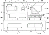
The invention discloses a three-dimensional test bench for fast and accurate detection of a motor and a test method thereof, relates to the technical field of motor test benches, and aims to solve the problem that when the motor in the current market is tested, manual shaft center alignment work is needed, so that shaft center deviation is easy to occur, and the test is inaccurate. The fixed backup pad that is provided with in top of base, the fixed load machine support that is provided with in one side of backup pad top, the fixed protection casing that is provided with in the outside of backup pad top, one side of load machine support is provided with first sliding seat, the top of first sliding seat slides and is provided with the second sliding seat, the top of second sliding seat slides and is provided with the third sliding seat, the third sliding seat top slides and is provided with motor right angle seat or motor side board seat, one side of motor right angle seat and motor side board seat is provided with looks for the laser mechanism, one side that the test motor shaft coupling is close to motor right angle seat and motor side board seat is provided with the alignment light receiving mechanism.
Description
Technical Field
The invention relates to the technical field of motor test tables, in particular to a three-dimensional test table for quickly and accurately detecting a motor and a test method thereof.
Background
The motor test bench is a device for specially testing the performance of the diesel generator set. The motor test board can test the delivery performance of diesel engine generator sets such as power frequency/medium frequency, high voltage/low voltage, fuel oil/gas, single machine/parallel machine and the like. The test board equipment of the generator set is configured with professional test software and a professional industrial control computer, and related power parameters are calculated by sampling and processing the three-phase voltage and the three-phase current of the system at a high speed. The motor test bed provides important data support for motor design, quality inspection and the like, and is a dual platform for motor enterprise quality management and technical research and development. The test board is connected with the accompanying motor in series through a torque and rotating speed sensor through a tested motor, mutual torsion torque and real-time rotating speed between the motors are detected by the sensor in real time, and the torque, the rotating speed and the power of the motors are synchronously displayed through the measuring instrument. The tested motor and the load motor are controlled by a frequency converter or a controller.
At present, during motor testing on the market, most of motors need to be manually subjected to shaft center alignment work, so that shaft center deviation is easy to occur, micro vibration occurs in transmission, and testing is inaccurate.
Disclosure of Invention
The invention aims to provide a three-dimensional test bench for fast and accurate detection of a motor and a test method thereof, and aims to solve the problems that when the motor in the market is tested in the background technology, most of motors in the market need to be manually subjected to axis alignment, so that axis deviation is easy to occur, and micro-vibration occurs in transmission, so that the test is inaccurate.
In order to achieve the purpose, the invention provides the following technical scheme: the utility model provides a quick accurate three-dimensional test platform of using that detects of motor, includes base and motor side board seat, the fixed backup pad that is provided with in top of base, the fixed load machine support that is provided with in one side of backup pad top, the fixed protection casing that is provided with in the outside of backup pad top, one side of load machine support is provided with first sliding seat, the top of first sliding seat slides and is provided with the second sliding seat, the top of second sliding seat slides and is provided with the third sliding seat, third sliding seat top slides and is provided with motor right angle seat or motor side board seat, one side of motor right angle seat and motor side board seat is provided with alignment laser mechanism, one side that test motor shaft coupling is close to motor right angle seat and motor side board seat is provided with alignment receipts optical mechanism, the one end of looking for alignment laser mechanism is provided with correlation laser sensor transmission end box, the inside of correlation laser sensor transmission end box is provided with correlation laser sensor transmission end, alignment receipts optical mechanism's one end is provided with correlation laser sensor receiving end, and correlation laser sensor receiving end sets up with correlation laser sensor transmission end relatively.
Preferably, a loading machine is arranged on one side above the loading machine support, a loading machine coupler is arranged on one side of the loading machine, a sensor seat is arranged on one side of the loading machine coupler, a testing motor coupler is arranged on one side of the sensor seat, and eight damping bases are arranged on two sides of the base in a rectangular mode.
Preferably, both sides of the lower part of the first sliding seat are fixedly provided with limiting rods, limiting rod sleeves are sleeved outside the limiting rods and are in sliding connection with the limiting rods, and the lower ends of the limiting rod sleeves are fixedly connected with the supporting plate.
Preferably, the fixed lifting drive mechanism that is provided with in below of backup pad, lifting drive mechanism's rear end is provided with lift driving motor, lift driving motor's inside is provided with lifting gear, and lifting gear is connected with the lift driving motor transmission, two be provided with lifting threaded rod between the gag lever post, and lifting threaded rod's upper end and first sliding seat fixed connection, lifting threaded rod and backup pad threaded connection, and lifting threaded rod is connected with the lifting gear transmission.
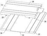
Preferably, bilateral symmetry on the upper end of the first sliding seat is provided with first sliding block grooves, limiting side grooves are symmetrically formed in the upper sides of the two ends of the first sliding seat, bilateral symmetry on the lower end of the second sliding seat is provided with first sliding blocks, the first sliding blocks are connected with the first sliding block grooves in a sliding mode, limiting sides are symmetrically arranged on the lower sides of the two ends of the second sliding seat and correspond to the limiting side grooves, a first lead screw is arranged on one side of each of the first sliding seat and the second sliding seat, the fixed end of the first lead screw is connected with the first sliding seat in a rotating mode through a bearing, the transmission end of the first lead screw is fixedly connected with the second sliding seat, two sets of second sliding block grooves are symmetrically arranged on the upper end of the second sliding seat, the lower end of the third sliding seat is connected with the second sliding block grooves in a sliding mode, a second lead screw is arranged on one side above the second sliding seat, the fixed end of the second lead screw is connected with the second sliding seat in a rotating mode through a bearing, and the fixed end of the second lead screw is fixedly connected with the third sliding seat.
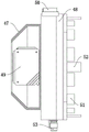
Preferably, be provided with the right angle backup pad on the motor right angle seat, one side of motor side board seat upper end is provided with motor side board seat motor connecting plate, the intermediate position department of motor side board seat motor connecting plate and right angle backup pad one end is provided with the output slot, the outside annular in output slot is provided with four and looks for positive laser mechanism stop block grooves, the annular all around of output slot is provided with eight right angle backup pad grooves on the motor side board seat motor connecting plate, the fixed right angle connecting plate that is provided with of bilateral symmetry around the right angle backup pad upper end, the lower extreme of motor side board seat is provided with motor side board seat bottom plate, the lower extreme symmetry of motor side board seat bottom plate and right angle backup pad is provided with the second sliding block, and the upper end sliding connection of second sliding block and third sliding seat, the both sides of motor side board seat bottom plate top all are provided with motor side board seat backup pad, symmetry is provided with motor side board seat mounting panel around the top of motor side board seat backup pad, and the one end downward sloping that motor side board seat mounting panel is close to motor side board seat center, the inside equidistance of motor side board seat mounting panel is seted up and is had three motor side board groove.
Preferably, the rear end of protection casing is provided with the protection casing backplate, the both ends of protection casing are provided with the protection casing curb plate, the inboard intermediate position department of protection casing curb plate is provided with the curb plate and inhales the sound region, the inboard border position department of protection casing curb plate is provided with the protection casing spout, the front end of protection casing is provided with four protection casing sliding plates, and is adjacent set up between the protection casing sliding plate and rotate through protection casing sliding connection pivot and be connected, and protection casing sliding connection pivot and protection casing spout sliding connection, the inner wall of protection casing backplate upper end is provided with press switch, and press switch is located one side of upper end protection casing sliding plate, press switch's the fixed switch protection film that is provided with in below, and the lower extreme of switch protection film is less than the up end of upper end protection casing sliding plate.
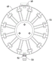
Preferably, one side of correlation laser sensor transmitting terminal box is provided with motor output end chuck, the upper end of motor output end chuck is provided with inclination sensor, the below of motor output end chuck is provided with motor output end chuck driving motor, and motor output end chuck driving motor is connected with the transmission of motor output end chuck, the one end annular of motor output end chuck is provided with twelve motor output end chuck fixture blocks, one side annular of motor output end chuck is provided with four and looks for the laser mechanism stopper, and looks for laser mechanism stopper and the setting of alignment laser mechanism stopper groove correspondence.
Preferably, one side of alignment receipts optical mechanism upper end is provided with alignment receipts optical mechanism fixed plate, and alignment receipts optical mechanism fixed plate and test motor shaft coupling fixed connection, the top of alignment receipts optical mechanism fixed plate is provided with the alignment and receives the optical mechanism connecting rod, the below of alignment receipts optical mechanism connecting rod one end is provided with correlation laser sensor receiving end fixed block, and correlation laser sensor receiving end fixed block and correlation laser sensor receiving end fixed connection, alignment receipts optical mechanism connecting rod is the V-arrangement structure.
A testing method of a three-dimensional test bench for rapid and accurate detection of a motor comprises the following steps:
step 1: firstly, selecting a motor right-angle seat or a motor side plate seat according to the shape of the motor and the installation position of a fixing screw, aligning and slidably connecting the upper end of a third sliding seat through a second sliding block, fixing a test motor on the motor right-angle seat by penetrating a screw through a right-angle supporting plate screw groove through the screw, and fixing the test motor on the motor side plate seat by penetrating the screw through a motor side plate seat screw groove through the screw;
step 2: the output end of the test motor penetrates through an output end groove, an alignment laser mechanism is sleeved on the output end of the test motor, an alignment laser mechanism limiting block and the alignment laser mechanism limiting block groove are aligned and installed at first, the output end of the test motor is arranged between motor output end chuck blocks, the motor is driven by the motor output end chuck, the motor output end chuck blocks move inwards along with the driving, so that the output end of the test motor is clamped, the horizontal condition of the alignment light-receiving mechanism at the time is obtained through an inclination angle sensor, so that whether the test motor is horizontally installed or not can be determined, adjustment is carried out when the test motor is not horizontally installed, then a butt laser sensor receiving end fixing block rotates downwards along with a rotating shaft between the butt laser sensor receiving end fixing block and the alignment light-receiving mechanism connecting rod, and the butt laser sensor receiving end faces the alignment light-receiving mechanism;
and step 3: starting an emitting end of an opposite laser sensor to emit laser, simultaneously starting a receiving end of the opposite laser sensor to sense the laser, adjusting the center of a testing motor according to the center of a coupling of the testing motor, driving a second sliding seat to slide above a first sliding seat through a first lead screw, driving a third sliding seat to slide above the second sliding seat through a second lead screw, and driving a lifting gear to rotate through a lifting driving motor so as to drive a lifting threaded rod which is in meshing connection to slide up and down, so that the first sliding seat can carry out height adjustment, and when the receiving end of the opposite laser sensor senses the laser emitted by the emitting end of the opposite laser sensor, alignment of the axis of the testing motor is finished;
and 4, step 4: the alignment light-collecting mechanism connecting rod is connected with the alignment light-collecting mechanism connecting rod through a shaft;
and 5: gripping protection casing handle pulling protection casing sliding plate down, the protection casing sliding plate rotates downwards along with the protection casing spout to the spacing of protection casing sliding connection pivot, and when the protection casing was closed completely, the protection casing was relieved and is pressed press switch, press switch-on test equipment power, alright begin to test.
Compared with the prior art, the invention has the beneficial effects that:
1. the invention firstly realizes the up-and-down adjustment of the lifting screw rod on the first sliding seat through the arrangement of the lifting driving mechanism and the meshing connection with the lifting screw rod through the arrangement of the gear, thereby facilitating the alignment of a test motor, simultaneously limits the up-and-down moving direction of the limiting rod through the limiting of the limiting rod sleeve, thereby limiting the up-and-down adjustment of the first sliding seat, simultaneously drives the second sliding seat to slide back and forth above the first sliding seat through the first lead screw, drives the third sliding seat to slide left and right above the second sliding seat through the second lead screw, thereby facilitating the accurate alignment work, the alignment laser mechanism is clamped outside the output end of the test motor through a chuck at the output end of the motor, simultaneously, the chuck at the output end of the motor and a limiting block groove of the alignment laser mechanism are correspondingly arranged, thereby facilitating the maintenance of the horizontal state of the alignment laser mechanism through the chuck at the output end of the motor, the inclination angle of the test motor is monitored through the alignment sensor, when the inclination occurs, the alignment laser emitted by the emitter end of the alignment laser sensor arranged on the alignment laser sensor is correspondingly arranged on the alignment light-receiving mechanism, thereby facilitating the rapid detection of the axis deviation of the laser emission of the laser sensor, thereby facilitating the detection of the motor, and facilitating the rapid detection of the inaccuracy of the axis of the motor.
2. According to the invention, the protective cover is arranged to protect the three-dimensional test board, when a test is required, the protective cover sliding plate can be pulled down, the protective cover is limited by the protective cover sliding groove in a sliding connection mode with the rotating shaft, so that the rotation of the protective cover sliding plate is limited, when the protective cover sliding plate is opened, the protective cover sliding plate can trigger the press switch, so that the test equipment is powered off, the situation that a speed measuring motor is assembled and disassembled, the switch is touched by mistake during debugging work is prevented, and the safety of working personnel during work is improved.
Drawings
FIG. 1 is a schematic view of the structure of the present invention;
FIG. 2 is a view showing a connection relationship between a support plate and a first sliding seat in the present invention;
FIG. 3 is an exploded view of the first and second slide blocks of the present invention;
FIG. 4 is a perspective view of a motor right angle block of the present invention;
FIG. 5 is a perspective view of a motor side plate mount of the present invention;
FIG. 6 is a schematic structural view of a shield according to the present invention;
FIG. 7 is a schematic structural diagram of a laser alignment mechanism according to the present invention;
FIG. 8 is a side view of the motor output end chuck of the present invention;
FIG. 9 is an enlarged view of a portion of the area A of FIG. 1 according to the present invention;
FIG. 10 is a partial enlarged view of the area B in FIG. 6 according to the present invention.
In the figure: 1. a base; 2. a support plate; 3. a loader bracket; 4. a damping mount; 5. a loading machine; 6. a loader coupling; 7. a sensor seat; 8. testing the motor coupler; 9. testing the motor; 10. aligning the laser mechanism; 11. aligning the light receiving mechanism; 12. a motor right-angle seat; 13. a first sliding seat; 14. a second sliding seat; 15. a third sliding seat; 16. a first slider groove; 17. a limiting rod; 18. a limiting rod sleeve; 19. lifting a threaded rod; 20. a lifting drive mechanism; 21. a lifting drive motor; 22. a lifting gear; 23. a first lead screw; 24. a second lead screw; 25. a first slider; 26. a second slider groove; 27. a limit side groove; 28. a limiting edge; 29. a right-angled support plate; 30. an output end slot; 31. a screw slot of the right-angle support plate; 32. a positive laser mechanism limiting block groove is found; 33. a right-angle connecting plate; 34. a second slider; 35. a motor side plate base plate; 36. a motor side plate base support plate; 37. a motor side plate base mounting plate; 38. a screw slot of the motor side plate seat; 39. a protective cover; 40. a shield back plate; 41. a protective cover chute; 42. a shield side plate; 43. a protective cover sliding plate; 44. the protective cover is connected with the rotating shaft in a sliding manner; 45. a shield handle; 46. a side panel sound absorption area; 47. the emitting end box of the correlation laser sensor; 48. a chuck at the output end of the motor; 49. a transmitting end of the correlation laser sensor; 50. a tilt sensor; 51. a chuck block at the output end of the motor; 52. aligning a laser mechanism limiting block; 53. the chuck at the output end of the motor drives the motor; 54. aligning the fixing plate of the light collecting mechanism; 55. aligning the connecting rod of the light collecting mechanism; 56. a receiving end fixing block of the correlation laser sensor; 57. a receiving end of the correlation laser sensor; 58. a motor side plate base; 59. a push switch; 60. a switch protection film; 61. motor connecting plate of motor side panel seat.
Detailed Description
The technical solutions in the embodiments of the present invention will be clearly and completely described below with reference to the drawings in the embodiments of the present invention, and it is obvious that the described embodiments are only a part of the embodiments of the present invention, and not all of the embodiments.
Referring to fig. 1-10, an embodiment of the present invention is shown: the utility model provides a quick accurate three-dimensional test platform of using that detects of motor, including base 1 and motor side plate seat 58, the fixed backup pad 2 that is provided with in top of base 1, one side of backup pad 2 top is fixed and is provided with load machine support 3, the fixed protection casing 39 that is provided with in outside of backup pad 2 top, one side of load machine support 3 is provided with first sliding seat 13, the top of first sliding seat 13 is slided and is provided with second sliding seat 14, the top of second sliding seat 14 is slided and is provided with third sliding seat 15, third sliding seat 15 top is slided and is provided with motor right angle seat 12 or motor side plate seat 58, one side of motor right angle seat 12 and motor side plate seat 58 is provided with alignment light receiving mechanism 10, one side that test motor shaft coupling 8 is close to motor right angle seat 12 and motor side plate seat 58 is provided with alignment light receiving mechanism 11, the one end of alignment laser mechanism 10 is provided with correlation laser sensor transmission end box 47, the inside of correlation laser sensor transmission end box 47 is provided with correlation laser sensor transmission end 49, the one end of alignment light receiving mechanism 11 is provided with correlation laser sensor 57, and the receiving end 57 sets up correlation laser sensor transmission end 49.
Referring to fig. 1, a loader 5 is arranged on one side above a loader support 3, a loader coupler 6 is arranged on one side of the loader 5, a sensor base 7 is arranged on one side of the loader coupler 6, a test motor coupler 8 is arranged on one side of the sensor base 7, and eight shock absorption bases 4 are arranged on two sides below a base 1 in a rectangular manner.
Referring to fig. 2, two sides of the lower portion of the first sliding seat 13 are fixedly provided with a limiting rod 17, a limiting rod sleeve 18 is sleeved outside the limiting rod 17, the limiting rod sleeve 18 is slidably connected with the limiting rod 17, and the lower end of the limiting rod sleeve 18 is fixedly connected with the supporting plate 2.
Referring to fig. 2, a lifting driving mechanism 20 is fixedly disposed below the supporting plate 2, a lifting driving motor 21 is disposed at the rear end of the lifting driving mechanism 20, a lifting gear 22 is disposed inside the lifting driving motor 21, the lifting gear 22 is in transmission connection with the lifting driving motor 21, a lifting threaded rod 19 is disposed between the two limiting rods 17, the upper end of the lifting threaded rod 19 is fixedly connected with the first sliding seat 13, the lifting threaded rod 19 is in threaded connection with the supporting plate 2, and the lifting threaded rod 19 is in transmission connection with the lifting gear 22.
Referring to fig. 1, 2 and 3, first sliding block grooves 16 are symmetrically formed in two sides of an upper end of a first sliding seat 13, limit side grooves 27 are symmetrically formed in upper sides of two ends of the first sliding seat 13, first sliding blocks 25 are symmetrically formed in two sides of a lower end of a second sliding seat 14, the first sliding blocks 25 are slidably connected with the first sliding block grooves 16, limit sides 28 are symmetrically formed in lower sides of two ends of the second sliding seat 14, the limit sides 28 are arranged corresponding to the limit side grooves 27, first lead screws 23 are arranged on one sides of the first sliding seat 13 and the second sliding seat 14, a fixed end of each first lead screw 23 is rotatably connected with the first sliding seat 13 through a bearing, a transmission end of each first lead screw 23 is fixedly connected with the second sliding seat 14, two groups of second sliding block grooves 26 are symmetrically formed in an upper end of the second sliding seat 14, a lower end of each third sliding seat 15 is slidably connected with the second sliding block grooves 26, a fixed end of each second lead screw 24 is rotatably connected with the second sliding seat 14 through a bearing, and a fixed end of each second lead screw 15 is fixedly connected with the second sliding seat.
Referring to fig. 4 and 5, a right-angle support plate 29 is disposed on the motor right-angle base 12, a motor side plate base motor connecting plate 61 is disposed on one side of the upper end of the motor side plate base 58, an output end slot 30 is disposed at the middle position of the motor side plate base motor connecting plate 61 and one end of the right-angle support plate 29, four alignment laser mechanism limiting block slots 32 are annularly disposed on the outer side of the output end slot 30, eight right-angle support plate screw slots 31 are annularly disposed around the output end slot 30 on the motor side plate base motor connecting plate 61, right-angle connecting plates 33 are symmetrically and fixedly disposed on the front side and the rear side of the upper end of the right-angle support plate 29, a motor side plate base bottom plate 35 is disposed on the lower end of the motor side plate base support plate 58, second side plate bases 34 are symmetrically disposed on the lower ends of the motor side plate base bottom plate 35 and the right-angle support plate 29, the second side plate bases 34 are slidably connected with the upper end of the third sliding base 15, motor side plate base support plates 36 are disposed on both sides above the motor side plate base bottom plate 35, sliding blocks 37 are symmetrically disposed on the front side and rear side of the motor side plate base sliding plates 38, and the motor side plate mounting plates 37 are disposed with three sliding blocks 38 inclined downward.
Referring to fig. 6 and 10, a shield back plate 40 is disposed at the rear end of the shield 39, shield side plates 42 are disposed at two ends of the shield 39, a side plate sound absorption region 46 is disposed at the middle position of the inner side of the shield side plates 42, shield sliding grooves 41 are disposed at the edge position of the inner side of the shield side plates 42, four shield sliding plates 43 are disposed at the front end of the shield 39, adjacent shield sliding plates 43 are rotatably connected through a shield sliding connection rotating shaft 44, the shield sliding connection rotating shaft 44 is slidably connected with the shield sliding grooves 41, a push switch 59 is disposed on the inner wall of the upper end of the shield back plate 40, the push switch 59 is located on one side of the upper end shield sliding plate 43, a switch protection film 60 is fixedly disposed below the push switch 59, and the lower end of the switch protection film 60 is lower than the upper end surface of the upper end shield sliding plate 43.
Referring to fig. 4, 5 and 7, a motor output end chuck 48 is disposed on one side of the emission end box 47 of the correlation laser sensor, an inclination angle sensor 50 is disposed at the upper end of the motor output end chuck 48, a motor output end chuck driving motor 53 is disposed below the motor output end chuck 48, the motor output end chuck driving motor 53 is in transmission connection with the motor output end chuck 48, twelve motor output end chuck clamping blocks 51 are annularly disposed at one end of the motor output end chuck 48, four alignment laser mechanism limiting blocks 52 are annularly disposed on one side of the motor output end chuck 48, and the alignment laser mechanism limiting blocks 52 are correspondingly disposed with the alignment laser mechanism limiting block grooves 32.
Referring to fig. 9, an alignment light-receiving mechanism fixing plate 54 is disposed on one side of the upper end of the alignment light-receiving mechanism 11, the alignment light-receiving mechanism fixing plate 54 is fixedly connected to the testing motor coupler 8, an alignment light-receiving mechanism connecting rod 55 is disposed above the alignment light-receiving mechanism fixing plate 54, an alignment laser sensor receiving end fixing block 56 is disposed below one end of the alignment light-receiving mechanism connecting rod 55, the alignment laser sensor receiving end fixing block 56 is fixedly connected to an alignment laser sensor receiving end 57, and the alignment light-receiving mechanism connecting rod 55 is of a V-shaped structure.
A testing method of a three-dimensional test bench for rapid and accurate detection of a motor comprises the following steps:
step 1: firstly, selecting a motor right-angle seat 12 or a motor side plate seat 58 according to the shape of the motor and the installation position of a fixing screw, aligning and slidably connecting the upper end of a third sliding seat 15 through a second sliding block 34, fixing a test motor 9 on the motor right-angle seat 12 by passing a screw through a right-angle supporting plate screw groove 31, and fixing the test motor 9 on the motor side plate seat 58 by passing a screw through a motor side plate seat screw groove 38;
step 2: at the moment, the output end of the test motor 9 penetrates through the output end groove 30, the alignment laser mechanism 10 is sleeved on the output end of the test motor 9, the alignment laser mechanism limiting block 52 and the alignment laser mechanism limiting block groove 32 are firstly installed in an aligned mode, the output end of the test motor 9 is arranged between the motor output end chuck clamping blocks 51, the motor output end chuck clamping blocks 51 move inwards along with the driving through the driving of the motor output end chuck driving motor 53, so that the output end of the test motor 9 is clamped, the horizontal condition of the alignment light receiving mechanism 11 at the moment is obtained through the inclination angle sensor 50, so that whether the test motor 9 is horizontally installed or not can be determined, the adjustment is carried out when the test motor is not horizontally installed, then the alignment laser sensor receiving end fixing block 56 rotates downwards along with a rotating shaft between the alignment light receiving mechanism connecting rod 55, and the alignment laser sensor receiving end 57 faces the alignment light receiving mechanism 11;
and step 3: starting the emitting end 49 of the correlation laser sensor to emit laser, simultaneously starting the receiving end 57 of the correlation laser sensor to sense the laser, adjusting the center of the testing motor 9 according to the center of the testing motor coupler 8, driving the second sliding seat 14 to slide above the first sliding seat 13 through the first lead screw 23, driving the third sliding seat 15 to slide above the second sliding seat 14 through the second lead screw 24, driving the lifting gear 22 to rotate through the lifting driving motor 21, driving the lifting threaded rod 19 connected in a meshed manner to slide up and down, adjusting the height of the first sliding seat 13, and finishing the alignment of the axis of the testing motor 9 when the receiving end 57 of the correlation laser sensor senses the laser emitted by the emitting end 49 of the correlation laser sensor;
and 4, step 4: the alignment light-collecting mechanism connecting rod 55 is connected with the alignment light-collecting mechanism connecting rod through the second sliding block 34 and the third sliding seat 15;
and 5: when the protective cover 39 is completely closed, the protective cover 39 releases the pressing of the push switch 59, the push switch 59 is connected with the power supply of the test equipment, and the test can be started.
It will be evident to those skilled in the art that the invention is not limited to the details of the foregoing illustrative embodiments, and that the present invention may be embodied in other specific forms without departing from the spirit or essential attributes thereof. The present embodiments are therefore to be considered in all respects as illustrative and not restrictive, the scope of the invention being indicated by the appended claims rather than by the foregoing description, and all changes which come within the meaning and range of equivalency of the claims are therefore intended to be embraced therein. Any reference sign in a claim should not be construed as limiting the claim concerned.
Claims (8)
1. The utility model provides a quick accurate three-dimensional test platform of using that detects of motor, includes base (1), test motor coupling (8) and motor curb plate seat (58), its characterized in that: the device is characterized in that a supporting plate (2) is fixedly arranged above the base (1), a load machine support (3) is fixedly arranged on one side above the supporting plate (2), a protective cover (39) is fixedly arranged on the outer side above the supporting plate (2), a first sliding seat (13) is arranged on one side of the load machine support (3), a second sliding seat (14) is slidably arranged above the first sliding seat (13), a third sliding seat (15) is slidably arranged above the second sliding seat (14), a motor right angle seat (12) or a motor side plate seat (58) is slidably arranged above the third sliding seat (15), an alignment light receiving mechanism (11) is arranged on one side of the motor right angle seat (12) and the motor side plate seat (58), an alignment laser sensor transmitting end box (47) is arranged at one end of the alignment laser mechanism (10), an alignment laser sensor transmitting end (57) is arranged on one side of the test motor coupler (8) close to the motor right angle seat (12) and the motor side plate seat (58), a laser sensor transmitting end (49) is arranged on the other end of the alignment laser sensor transmitting end (47), and a laser sensor receiving end (49) is arranged opposite to the laser sensor transmitting end of the laser sensor (49), one side of the transmitting end box (47) of the correlation laser sensor is provided with a motor output end chuck (48), an inclination angle sensor (50) is arranged at the upper end of the motor output end chuck (48), a motor output end chuck driving motor (53) is arranged below the motor output end chuck (48), and the motor output end chuck driving motor (53) is in transmission connection with the motor output end chuck (48), twelve electric motor output end chuck clamping blocks (51) are annularly arranged at one end of the electric motor output end chuck (48), one side of the motor output end chuck (48) is annularly provided with four alignment laser mechanism limiting blocks (52), and the alignment laser mechanism limiting block (52) is arranged corresponding to the alignment laser mechanism limiting block groove (32), one side of the upper end of the alignment light-receiving mechanism (11) is provided with an alignment light-receiving mechanism fixing plate (54), and the alignment light-collecting mechanism fixing plate (54) is fixedly connected with the test motor coupler (8), an alignment and light-receiving mechanism connecting rod (55) is arranged above the alignment and light-receiving mechanism fixing plate (54), a butt laser sensor receiving end fixing block (56) is arranged below one end of the alignment and light-collecting mechanism connecting rod (55), and the correlation laser sensor receiving end fixing block (56) is fixedly connected with the correlation laser sensor receiving end (57), and the alignment light-receiving mechanism connecting rod (55) is of a V-shaped structure.
2. The three-dimensional test bench for rapid and accurate detection of the motor according to claim 1, wherein: one side of load machine support (3) top is provided with load machine (5), one side of load machine (5) is provided with load machine shaft coupling (6), one side of load machine shaft coupling (6) is provided with sensor seat (7), one side of sensor seat (7) is provided with test motor shaft coupling (8), the both sides rectangle of base (1) below is provided with eight vibration damping mount (4).
3. The three-dimensional test bench for rapid and accurate detection of the motor according to claim 1, wherein: the limiting rod (17) is fixedly arranged on two sides of the lower portion of the first sliding seat (13), a limiting rod sleeve (18) is sleeved outside the limiting rod (17), the limiting rod sleeve (18) is in sliding connection with the limiting rod (17), and the lower end of the limiting rod sleeve (18) is fixedly connected with the supporting plate (2).
4. The three-dimensional test bench for rapid and accurate detection of the motor according to claim 3, wherein: the fixed lifting drive mechanism (20) that is provided with in below of backup pad (2), the rear end of lifting drive mechanism (20) is provided with lift driving motor (21), the inside of lift driving motor (21) is provided with lifting gear (22), and lifting gear (22) are connected with lift driving motor (21) transmission, two be provided with lifting threaded rod (19) between gag lever post (17), and the upper end and first sliding seat (13) fixed connection of lifting threaded rod (19), lifting threaded rod (19) and backup pad (2) threaded connection, and lifting threaded rod (19) are connected with lifting gear (22) transmission.
5. The three-dimensional test bench for rapid and accurate detection of the motor according to claim 1, wherein: the utility model discloses a lead screw structure, including first sliding seat (13), second sliding seat (14), first lead screw (14), second sliding seat (24), first lead screw (23), second sliding seat (24), first slider groove (16), spacing limit groove (27) have been seted up to the upside symmetry at first sliding seat (13) both ends, the downside symmetry at second sliding seat (14) both ends is provided with spacing limit (28), and just spacing limit (28) correspond the setting with spacing limit groove (27), one side of first sliding seat (13) and second sliding seat (14) is provided with first lead screw (23), the stiff end of first lead screw (23) passes through the bearing and is connected with first sliding seat (13) rotation, and the transmission end of first lead screw (23) and second sliding seat (14) fixed connection, the upper end symmetry of second sliding seat (14) is provided with two sets of second sliding seat (26), the lower extreme and the second sliding seat (26) of third sliding seat (15) are connected with second sliding seat (26), the sliding seat (14) top sliding seat (24) is provided with second lead screw (24) and second sliding seat (24) rotation, the stiff end of second sliding seat (24) is connected with second lead screw (24), and second sliding seat (24) one side.
6. The three-dimensional test bench for rapid and accurate detection of the motor according to claim 1, wherein: be provided with right angle backup pad (29) on motor right angle cabinet (12), one side of motor side board seat (58) upper end is provided with motor side board seat motor connecting plate (61), the intermediate position department of motor side board seat motor connecting plate (61) and right angle backup pad (29) one end is provided with output end groove (30), the outside annular of output end groove (30) is provided with four and looks for positive laser mechanism stop block groove (32), the annular all around of output end groove (30) is provided with eight right angle backup pad screw grooves (31) on motor side board seat motor connecting plate (61), the fixed right angle connecting plate (33) that is provided with of front and back bilateral symmetry of right angle backup pad (29) upper end, the lower extreme of motor side board seat (58) is provided with motor side board seat bottom plate (35), the lower extreme symmetry of motor side board seat bottom plate (35) and right angle backup pad (29) is provided with second sliding block (34), and the upper end sliding connection of third sliding seat (15), the both sides of motor side board seat bottom plate (35) top all is provided with motor side board backup pad (36), motor side board mounting plate (37) is provided with equidistance motor seat side mounting panel (37), motor side board mounting panel (37) is located around motor side board (37) and motor side mounting panel (37) the motor seat mounting panel (37) side mounting panel (37), motor side mounting panel (37) has the motor side board mounting panel (37) side mounting panel (37) has the motor side board (38).
7. The three-dimensional test bench for rapid and accurate detection of the motor according to claim 1, wherein: the rear end of protection casing (39) is provided with protection casing backplate (40), the both ends of protection casing (39) are provided with protection casing curb plate (42), the inboard intermediate position department of protection casing curb plate (42) is provided with the curb plate and inhales sound region (46), the inboard border position department of protection casing curb plate (42) is provided with protection casing spout (41), the front end of protection casing (39) is provided with four protection casing sliding plates (43), and is adjacent set up between protection casing sliding plates (43) and rotate through protection casing sliding connection pivot (44) and connect, and protection casing sliding connection pivot (44) and protection casing spout (41) sliding connection, the inner wall of protection casing backplate (40) upper end is provided with press switch (59), and press switch (59) are located one side of upper end protection casing sliding plate (43), the fixed switch protection film (60) that is provided with in below press switch (59), and the lower extreme of switch protection film (60) is less than the up terminal surface of upper end sliding plate (43).
8. The method for testing the three-dimensional test bench for quickly and accurately testing the motor according to any one of claims 1 to 7 is characterized by comprising the following steps of:
step 1: firstly, a motor right-angle seat (12) or a motor side plate seat (58) is selected according to the shape of the motor and the installation position of a fixing screw, the second sliding block (34) is aligned with the upper end of a third sliding seat (15) and is in sliding connection with the upper end of the third sliding seat, a testing motor (9) is fixed on the motor right-angle seat (12) by passing a screw through a right-angle supporting plate screw groove (31), and the testing motor (9) is fixed on the motor side plate seat (58) by passing a screw through a motor side plate seat screw groove (38);
step 2: at the moment, the output end of a test motor (9) penetrates through an output end groove (30), an alignment laser mechanism (10) is sleeved on the output end of the test motor (9), an alignment laser mechanism limiting block (52) and an alignment laser mechanism limiting block groove (32) are firstly installed in an aligned mode, the output end of the test motor (9) is arranged between motor output end chuck clamping blocks (51), the motor output end chuck clamping blocks (51) move inwards along with driving through the driving of a motor output end chuck driving motor (53), so that the output end of the test motor (9) is clamped, the horizontal condition of the alignment light-receiving mechanism (11) at the moment is obtained through an inclination angle sensor (50), whether the test motor (9) is installed horizontally or not can be determined, adjustment is carried out when the test motor is not installed horizontally, then an alignment laser sensor receiving end fixing block (56) rotates downwards along with a rotating shaft between the alignment light-receiving mechanism connecting rod (55), and accordingly an alignment laser sensor receiving end (57) faces the alignment light-receiving mechanism (11);
and step 3: starting an emitting end (49) of an opposite laser sensor to emit laser, simultaneously starting a receiving end (57) of the opposite laser sensor to sense the laser, adjusting the center of a testing motor (9) according to the center of a coupling (8) of the testing motor, driving a second sliding seat (14) to slide above a first sliding seat (13) through a first lead screw (23), driving a third sliding seat (15) to slide above the second sliding seat (14) through a second lead screw (24), and driving a lifting gear (22) to rotate through a lifting driving motor (21), so that a lifting threaded rod (19) in meshed connection is driven to slide up and down, the first sliding seat (13) is subjected to height adjustment, and when the receiving end (57) of the opposite laser sensor senses the laser emitted by the emitting end (49) of the opposite laser sensor, alignment of the axis of the testing motor (9) is completed;
and 4, step 4: the alignment light-collecting mechanism connecting rod (55) is connected with a positioning light-collecting mechanism through a rotating shaft, the alignment light-collecting mechanism connecting rod (55) is connected with a transmission laser sensor receiving end fixing block (56) in an upward rotating mode, and the second sliding block (34) and the third sliding seat (15) slide to push the output end of the test motor (9) to the test motor coupler (8);
and 5: the protective cover sliding plate (43) is pulled downwards by grabbing the protective cover handle (45), the protective cover sliding plate (43) rotates downwards along with the limit of the protective cover sliding connection rotating shaft (44) by the protective cover sliding groove (41), when the protective cover (39) is completely closed, the protective cover (39) releases the pressing of the press switch (59), the press switch (59) is connected with the power supply of the test equipment, and then the test can be started.
Priority Applications (1)
| Application Number | Priority Date | Filing Date | Title |
|---|---|---|---|
| CN202210190203.6A CN114563701B (en) | 2022-02-28 | 2022-02-28 | Three-dimensional test bench for rapid and accurate detection of motor and test method thereof |
Applications Claiming Priority (1)
| Application Number | Priority Date | Filing Date | Title |
|---|---|---|---|
| CN202210190203.6A CN114563701B (en) | 2022-02-28 | 2022-02-28 | Three-dimensional test bench for rapid and accurate detection of motor and test method thereof |
Publications (2)
| Publication Number | Publication Date |
|---|---|
| CN114563701A CN114563701A (en) | 2022-05-31 |
| CN114563701B true CN114563701B (en) | 2023-01-13 |
Family
ID=81715838
Family Applications (1)
| Application Number | Title | Priority Date | Filing Date |
|---|---|---|---|
| CN202210190203.6A Active CN114563701B (en) | 2022-02-28 | 2022-02-28 | Three-dimensional test bench for rapid and accurate detection of motor and test method thereof |
Country Status (1)
| Country | Link |
|---|---|
| CN (1) | CN114563701B (en) |
Families Citing this family (1)
| Publication number | Priority date | Publication date | Assignee | Title |
|---|---|---|---|---|
| CN115876265B (en) * | 2023-02-16 | 2023-05-16 | 西安成立航空制造有限公司 | Aeroengine nozzle flow detection device |
Family Cites Families (7)
| Publication number | Priority date | Publication date | Assignee | Title |
|---|---|---|---|---|
| CN102294565B (en) * | 2011-08-15 | 2012-11-07 | 常熟通润汽车零部件股份有限公司 | Jack bracket welding device |
| CN105858477B (en) * | 2015-08-11 | 2017-08-01 | 孙富亮 | A kind of laser range finder of energy automatic position adjusting function |
| CN106154162B (en) * | 2016-08-31 | 2023-08-08 | 宁波菲仕技术股份有限公司 | Combined motor opposite-dragging test board and installation method thereof |
| CN207218410U (en) * | 2017-08-26 | 2018-04-10 | 青岛和成源金属制品有限公司 | A kind of motor mounting rack |
| CN208924070U (en) * | 2018-11-16 | 2019-05-31 | 襄阳五二五泵业有限公司 | A kind of motor and bearing block axis fast calibrating device |
| CN213504453U (en) * | 2020-09-16 | 2021-06-22 | 武汉诚迅联科技有限公司 | Protective cover convenient to install quickly for vibration disc |
| CN113251886B (en) * | 2021-04-21 | 2022-11-15 | 淮南师范学院 | Control motor test equipment |
-
2022
- 2022-02-28 CN CN202210190203.6A patent/CN114563701B/en active Active
Also Published As
| Publication number | Publication date |
|---|---|
| CN114563701A (en) | 2022-05-31 |
Similar Documents
| Publication | Publication Date | Title |
|---|---|---|
| AU2019101530A4 (en) | Industrial intelligent clamp device | |
| CN114563701B (en) | Three-dimensional test bench for rapid and accurate detection of motor and test method thereof | |
| CN210773903U (en) | Foundry goods desktop formula optics sudden strain of a muscle survey appearance | |
| CN111077511A (en) | Laser attenuation device, laser radar simulation test system and method thereof | |
| CN211506183U (en) | Watch detection jig and detection device comprising same | |
| CN117116174B (en) | OLED display screen conductivity testing device | |
| CN219142878U (en) | Motor rotating speed testing equipment for research and development of high-voltage frequency converter control system | |
| CN220040754U (en) | Radar target movement test bench | |
| CN219496192U (en) | Detection device for edging of vehicle-mounted lens | |
| CN210090641U (en) | Motor no-load test stand | |
| CN116499998A (en) | Auxiliary positioning device for retroreflection coefficient relative measurement method | |
| CN209689660U (en) | A kind of Multifunction Sensor performance detection machine | |
| CN209978832U (en) | Contour projector | |
| CN209707102U (en) | Spindle test stand frame | |
| CN111327891A (en) | Automatic high-precision multi-axis rotary camera detection equipment | |
| CN211909010U (en) | Automatic high-precision multi-axis rotary camera detection equipment | |
| CN220281282U (en) | Electric driving structure for inclined plane of instrument display screen | |
| CN216012124U (en) | One-key spring size detection equipment based on CCD | |
| CN220540691U (en) | Hollow glass tester convenient for placing test piece | |
| CN216927035U (en) | Automatic testing arrangement of power strip | |
| CN220416856U (en) | Meteorological projection presentation device | |
| CN212410023U (en) | Micro-transmittance test support | |
| CN217216585U (en) | Optical fiber fault positioning device based on FMCW technology | |
| CN220170968U (en) | Glowing filament tester | |
| CN115638956B (en) | Circuit optical test platform |
Legal Events
| Date | Code | Title | Description |
|---|---|---|---|
| PB01 | Publication | ||
| PB01 | Publication | ||
| SE01 | Entry into force of request for substantive examination | ||
| SE01 | Entry into force of request for substantive examination | ||
| GR01 | Patent grant | ||
| GR01 | Patent grant |