CN114556721A - Parallel O-band amplifier - Google Patents
Parallel O-band amplifier Download PDFInfo
- Publication number
- CN114556721A CN114556721A CN202080072518.XA CN202080072518A CN114556721A CN 114556721 A CN114556721 A CN 114556721A CN 202080072518 A CN202080072518 A CN 202080072518A CN 114556721 A CN114556721 A CN 114556721A
- Authority
- CN
- China
- Prior art keywords
- pump
- optical
- equal
- gain
- fiber
- Prior art date
- Legal status (The legal status is an assumption and is not a legal conclusion. Google has not performed a legal analysis and makes no representation as to the accuracy of the status listed.)
- Pending
Links
Images


Classifications
-
- H—ELECTRICITY
- H01—ELECTRIC ELEMENTS
- H01S—DEVICES USING THE PROCESS OF LIGHT AMPLIFICATION BY STIMULATED EMISSION OF RADIATION [LASER] TO AMPLIFY OR GENERATE LIGHT; DEVICES USING STIMULATED EMISSION OF ELECTROMAGNETIC RADIATION IN WAVE RANGES OTHER THAN OPTICAL
- H01S3/00—Lasers, i.e. devices using stimulated emission of electromagnetic radiation in the infrared, visible or ultraviolet wave range
- H01S3/05—Construction or shape of optical resonators; Accommodation of active medium therein; Shape of active medium
- H01S3/06—Construction or shape of active medium
- H01S3/063—Waveguide lasers, i.e. whereby the dimensions of the waveguide are of the order of the light wavelength
- H01S3/067—Fibre lasers
- H01S3/06754—Fibre amplifiers
- H01S3/06762—Fibre amplifiers having a specific amplification band
-
- H—ELECTRICITY
- H01—ELECTRIC ELEMENTS
- H01S—DEVICES USING THE PROCESS OF LIGHT AMPLIFICATION BY STIMULATED EMISSION OF RADIATION [LASER] TO AMPLIFY OR GENERATE LIGHT; DEVICES USING STIMULATED EMISSION OF ELECTROMAGNETIC RADIATION IN WAVE RANGES OTHER THAN OPTICAL
- H01S3/00—Lasers, i.e. devices using stimulated emission of electromagnetic radiation in the infrared, visible or ultraviolet wave range
- H01S3/05—Construction or shape of optical resonators; Accommodation of active medium therein; Shape of active medium
- H01S3/06—Construction or shape of active medium
- H01S3/063—Waveguide lasers, i.e. whereby the dimensions of the waveguide are of the order of the light wavelength
- H01S3/067—Fibre lasers
- H01S3/06708—Constructional details of the fibre, e.g. compositions, cross-section, shape or tapering
- H01S3/06729—Peculiar transverse fibre profile
- H01S3/06737—Fibre having multiple non-coaxial cores, e.g. multiple active cores or separate cores for pump and gain
-
- H—ELECTRICITY
- H01—ELECTRIC ELEMENTS
- H01S—DEVICES USING THE PROCESS OF LIGHT AMPLIFICATION BY STIMULATED EMISSION OF RADIATION [LASER] TO AMPLIFY OR GENERATE LIGHT; DEVICES USING STIMULATED EMISSION OF ELECTROMAGNETIC RADIATION IN WAVE RANGES OTHER THAN OPTICAL
- H01S3/00—Lasers, i.e. devices using stimulated emission of electromagnetic radiation in the infrared, visible or ultraviolet wave range
- H01S3/09—Processes or apparatus for excitation, e.g. pumping
- H01S3/091—Processes or apparatus for excitation, e.g. pumping using optical pumping
- H01S3/094—Processes or apparatus for excitation, e.g. pumping using optical pumping by coherent light
- H01S3/094003—Processes or apparatus for excitation, e.g. pumping using optical pumping by coherent light the pumped medium being a fibre
- H01S3/094007—Cladding pumping, i.e. pump light propagating in a clad surrounding the active core
-
- H—ELECTRICITY
- H01—ELECTRIC ELEMENTS
- H01S—DEVICES USING THE PROCESS OF LIGHT AMPLIFICATION BY STIMULATED EMISSION OF RADIATION [LASER] TO AMPLIFY OR GENERATE LIGHT; DEVICES USING STIMULATED EMISSION OF ELECTROMAGNETIC RADIATION IN WAVE RANGES OTHER THAN OPTICAL
- H01S3/00—Lasers, i.e. devices using stimulated emission of electromagnetic radiation in the infrared, visible or ultraviolet wave range
- H01S3/09—Processes or apparatus for excitation, e.g. pumping
- H01S3/091—Processes or apparatus for excitation, e.g. pumping using optical pumping
- H01S3/094—Processes or apparatus for excitation, e.g. pumping using optical pumping by coherent light
- H01S3/094049—Guiding of the pump light
-
- H—ELECTRICITY
- H01—ELECTRIC ELEMENTS
- H01S—DEVICES USING THE PROCESS OF LIGHT AMPLIFICATION BY STIMULATED EMISSION OF RADIATION [LASER] TO AMPLIFY OR GENERATE LIGHT; DEVICES USING STIMULATED EMISSION OF ELECTROMAGNETIC RADIATION IN WAVE RANGES OTHER THAN OPTICAL
- H01S3/00—Lasers, i.e. devices using stimulated emission of electromagnetic radiation in the infrared, visible or ultraviolet wave range
- H01S3/09—Processes or apparatus for excitation, e.g. pumping
- H01S3/091—Processes or apparatus for excitation, e.g. pumping using optical pumping
- H01S3/094—Processes or apparatus for excitation, e.g. pumping using optical pumping by coherent light
- H01S3/094061—Shared pump, i.e. pump light of a single pump source is used to pump plural gain media in parallel
-
- H—ELECTRICITY
- H01—ELECTRIC ELEMENTS
- H01S—DEVICES USING THE PROCESS OF LIGHT AMPLIFICATION BY STIMULATED EMISSION OF RADIATION [LASER] TO AMPLIFY OR GENERATE LIGHT; DEVICES USING STIMULATED EMISSION OF ELECTROMAGNETIC RADIATION IN WAVE RANGES OTHER THAN OPTICAL
- H01S3/00—Lasers, i.e. devices using stimulated emission of electromagnetic radiation in the infrared, visible or ultraviolet wave range
- H01S3/09—Processes or apparatus for excitation, e.g. pumping
- H01S3/091—Processes or apparatus for excitation, e.g. pumping using optical pumping
- H01S3/094—Processes or apparatus for excitation, e.g. pumping using optical pumping by coherent light
- H01S3/0941—Processes or apparatus for excitation, e.g. pumping using optical pumping by coherent light of a laser diode
- H01S3/09415—Processes or apparatus for excitation, e.g. pumping using optical pumping by coherent light of a laser diode the pumping beam being parallel to the lasing mode of the pumped medium, e.g. end-pumping
-
- H—ELECTRICITY
- H01—ELECTRIC ELEMENTS
- H01S—DEVICES USING THE PROCESS OF LIGHT AMPLIFICATION BY STIMULATED EMISSION OF RADIATION [LASER] TO AMPLIFY OR GENERATE LIGHT; DEVICES USING STIMULATED EMISSION OF ELECTROMAGNETIC RADIATION IN WAVE RANGES OTHER THAN OPTICAL
- H01S3/00—Lasers, i.e. devices using stimulated emission of electromagnetic radiation in the infrared, visible or ultraviolet wave range
- H01S3/23—Arrangements of two or more lasers not provided for in groups H01S3/02 - H01S3/22, e.g. tandem arrangements of separate active media
- H01S3/2383—Parallel arrangements
-
- H—ELECTRICITY
- H04—ELECTRIC COMMUNICATION TECHNIQUE
- H04B—TRANSMISSION
- H04B10/00—Transmission systems employing electromagnetic waves other than radio-waves, e.g. infrared, visible or ultraviolet light, or employing corpuscular radiation, e.g. quantum communication
- H04B10/29—Repeaters
- H04B10/291—Repeaters in which processing or amplification is carried out without conversion of the main signal from optical form
- H04B10/2912—Repeaters in which processing or amplification is carried out without conversion of the main signal from optical form characterised by the medium used for amplification or processing
-
- H—ELECTRICITY
- H04—ELECTRIC COMMUNICATION TECHNIQUE
- H04B—TRANSMISSION
- H04B10/00—Transmission systems employing electromagnetic waves other than radio-waves, e.g. infrared, visible or ultraviolet light, or employing corpuscular radiation, e.g. quantum communication
- H04B10/29—Repeaters
- H04B10/291—Repeaters in which processing or amplification is carried out without conversion of the main signal from optical form
- H04B10/293—Signal power control
- H04B10/294—Signal power control in a multiwavelength system, e.g. gain equalisation
-
- H—ELECTRICITY
- H01—ELECTRIC ELEMENTS
- H01S—DEVICES USING THE PROCESS OF LIGHT AMPLIFICATION BY STIMULATED EMISSION OF RADIATION [LASER] TO AMPLIFY OR GENERATE LIGHT; DEVICES USING STIMULATED EMISSION OF ELECTROMAGNETIC RADIATION IN WAVE RANGES OTHER THAN OPTICAL
- H01S3/00—Lasers, i.e. devices using stimulated emission of electromagnetic radiation in the infrared, visible or ultraviolet wave range
- H01S3/005—Optical devices external to the laser cavity, specially adapted for lasers, e.g. for homogenisation of the beam or for manipulating laser pulses, e.g. pulse shaping
- H01S3/0064—Anti-reflection devices, e.g. optical isolaters
-
- H—ELECTRICITY
- H01—ELECTRIC ELEMENTS
- H01S—DEVICES USING THE PROCESS OF LIGHT AMPLIFICATION BY STIMULATED EMISSION OF RADIATION [LASER] TO AMPLIFY OR GENERATE LIGHT; DEVICES USING STIMULATED EMISSION OF ELECTROMAGNETIC RADIATION IN WAVE RANGES OTHER THAN OPTICAL
- H01S3/00—Lasers, i.e. devices using stimulated emission of electromagnetic radiation in the infrared, visible or ultraviolet wave range
- H01S3/09—Processes or apparatus for excitation, e.g. pumping
- H01S3/091—Processes or apparatus for excitation, e.g. pumping using optical pumping
- H01S3/0912—Electronics or drivers for the pump source, i.e. details of drivers or circuitry specific for laser pumping
-
- H—ELECTRICITY
- H01—ELECTRIC ELEMENTS
- H01S—DEVICES USING THE PROCESS OF LIGHT AMPLIFICATION BY STIMULATED EMISSION OF RADIATION [LASER] TO AMPLIFY OR GENERATE LIGHT; DEVICES USING STIMULATED EMISSION OF ELECTROMAGNETIC RADIATION IN WAVE RANGES OTHER THAN OPTICAL
- H01S3/00—Lasers, i.e. devices using stimulated emission of electromagnetic radiation in the infrared, visible or ultraviolet wave range
- H01S3/09—Processes or apparatus for excitation, e.g. pumping
- H01S3/091—Processes or apparatus for excitation, e.g. pumping using optical pumping
- H01S3/094—Processes or apparatus for excitation, e.g. pumping using optical pumping by coherent light
- H01S3/094049—Guiding of the pump light
- H01S3/094053—Fibre coupled pump, e.g. delivering pump light using a fibre or a fibre bundle
-
- H—ELECTRICITY
- H01—ELECTRIC ELEMENTS
- H01S—DEVICES USING THE PROCESS OF LIGHT AMPLIFICATION BY STIMULATED EMISSION OF RADIATION [LASER] TO AMPLIFY OR GENERATE LIGHT; DEVICES USING STIMULATED EMISSION OF ELECTROMAGNETIC RADIATION IN WAVE RANGES OTHER THAN OPTICAL
- H01S3/00—Lasers, i.e. devices using stimulated emission of electromagnetic radiation in the infrared, visible or ultraviolet wave range
- H01S3/09—Processes or apparatus for excitation, e.g. pumping
- H01S3/091—Processes or apparatus for excitation, e.g. pumping using optical pumping
- H01S3/094—Processes or apparatus for excitation, e.g. pumping using optical pumping by coherent light
- H01S3/094065—Single-mode pumping
-
- H—ELECTRICITY
- H01—ELECTRIC ELEMENTS
- H01S—DEVICES USING THE PROCESS OF LIGHT AMPLIFICATION BY STIMULATED EMISSION OF RADIATION [LASER] TO AMPLIFY OR GENERATE LIGHT; DEVICES USING STIMULATED EMISSION OF ELECTROMAGNETIC RADIATION IN WAVE RANGES OTHER THAN OPTICAL
- H01S3/00—Lasers, i.e. devices using stimulated emission of electromagnetic radiation in the infrared, visible or ultraviolet wave range
- H01S3/09—Processes or apparatus for excitation, e.g. pumping
- H01S3/091—Processes or apparatus for excitation, e.g. pumping using optical pumping
- H01S3/094—Processes or apparatus for excitation, e.g. pumping using optical pumping by coherent light
- H01S3/094069—Multi-mode pumping
-
- H—ELECTRICITY
- H01—ELECTRIC ELEMENTS
- H01S—DEVICES USING THE PROCESS OF LIGHT AMPLIFICATION BY STIMULATED EMISSION OF RADIATION [LASER] TO AMPLIFY OR GENERATE LIGHT; DEVICES USING STIMULATED EMISSION OF ELECTROMAGNETIC RADIATION IN WAVE RANGES OTHER THAN OPTICAL
- H01S3/00—Lasers, i.e. devices using stimulated emission of electromagnetic radiation in the infrared, visible or ultraviolet wave range
- H01S3/09—Processes or apparatus for excitation, e.g. pumping
- H01S3/091—Processes or apparatus for excitation, e.g. pumping using optical pumping
- H01S3/094—Processes or apparatus for excitation, e.g. pumping using optical pumping by coherent light
- H01S3/09408—Pump redundancy
-
- H—ELECTRICITY
- H01—ELECTRIC ELEMENTS
- H01S—DEVICES USING THE PROCESS OF LIGHT AMPLIFICATION BY STIMULATED EMISSION OF RADIATION [LASER] TO AMPLIFY OR GENERATE LIGHT; DEVICES USING STIMULATED EMISSION OF ELECTROMAGNETIC RADIATION IN WAVE RANGES OTHER THAN OPTICAL
- H01S3/00—Lasers, i.e. devices using stimulated emission of electromagnetic radiation in the infrared, visible or ultraviolet wave range
- H01S3/09—Processes or apparatus for excitation, e.g. pumping
- H01S3/091—Processes or apparatus for excitation, e.g. pumping using optical pumping
- H01S3/094—Processes or apparatus for excitation, e.g. pumping using optical pumping by coherent light
- H01S3/094096—Multi-wavelength pumping
Landscapes
- Physics & Mathematics (AREA)
- Electromagnetism (AREA)
- Engineering & Computer Science (AREA)
- Plasma & Fusion (AREA)
- Optics & Photonics (AREA)
- Computer Networks & Wireless Communication (AREA)
- Signal Processing (AREA)
- Optical Communication System (AREA)
- Lasers (AREA)
Abstract
A system (e.g., an optical amplifier) includes a gain fiber (e.g., a bismuth-doped fiber) for amplifying an optical signal. The optical signal has an operating center wavelength (λ 0) centered between about 1260 nanometers (1260 nm) and 1360nm (in the O band). The gain fibers are optically coupled to pump sources, the number of pump sources being less than or equal to the number of gain fibers. The pump source is (optionally) shared between the gain fibres, thereby providing more efficient resource usage.
Description
Cross Reference to Related Applications
This application claims the benefit of U.S. provisional patent application serial No. 62/902,634 entitled "parallell O-Band Amplifier" filed by Inniss at 19/9/2019, which is incorporated herein by reference in its entirety. The present application is also incorporated by reference in its entirety (as if expressly set forth) as international application (PCT) serial No. PCT/US19/51024 entitled "Bismuth taped Fiber Amplifier" filed in 2019, 13.9 in the name of inventor Luo and mikhalilov by the applicant OFS filtel, LLC.
Technical Field
The present disclosure relates generally to optical fibers and, more particularly, to optical communications in the original frequency band (O-band).
Background
Optical networks using the original frequency band (O-band) are typically single wavelength, point-to-point networks, often spanning distances between about five hundred meters (-500 m) and about ten kilometers (-10 km). However, conventional O-band networks are becoming increasingly impractical to support increasing data demands.
Disclosure of Invention
The present disclosure provides systems and methods for parallel raw band (O-band) optical amplification. Accordingly, one embodiment is a system (e.g., an optical amplifier) that includes a gain fiber (e.g., a bismuth-doped fiber) for amplifying an optical signal. The operating center wavelength (λ 0) of the optical signal is centered between about 1260 nanometers (-1260 nm) and-1360 nm (in the O-band). The gain fibers are optically coupled to pump sources, the number of pump sources being less than or equal to the number of gain fibers. Thus, for some embodiments, the pump source is shared between the gain fibers, providing more efficient resource usage.
With this in mind, other systems, devices, methods, features and advantages will be or will become apparent to one with skill in the art upon examination of the following figures and detailed description. It is intended that all such additional systems, methods, features and advantages be included within this description, be within the scope of the present disclosure, and be protected by the accompanying claims.
Drawings
Many aspects of the disclosure can be better understood with reference to the following drawings. The components in the drawings are not necessarily to scale, emphasis instead being placed upon clearly illustrating the principles of the present disclosure. Moreover, in the drawings, like reference numerals designate corresponding parts throughout the several views.
Fig. 1 is a block diagram illustrating components of an optical transmission system with corresponding signal loss (expressed in decibels (dB)).
FIG. 2 is a block diagram illustrating one embodiment of a parallel original band (O-band) optical amplifier system.
Fig. 3A is a block diagram illustrating a lateral view of one embodiment of a photonic lantern (photonic Lantern) that converts multi-mode (MM) signals to single-mode (SM) signals.
Fig. 3B is a block diagram illustrating an axial view of the photonic lantern of fig. 3A.
Fig. 4 is a block diagram illustrating one embodiment of a power equalizer.
FIG. 5 is a block diagram illustrating one embodiment of an optical transmission system for optically coupling one data center to another data center over a longer distance transmission fiber.
Figure 6 is a block diagram illustrating one embodiment of an optical transmission system for optically coupling a central node to a plurality of peripheral nodes over a longer distance transmission fiber.
Detailed Description
Due to cost considerations, point-to-point single wavelength raw band (O-band) communications are typically implemented over short distances (e.g., less than about ten kilometers (-10 km)), with data rates up to about ten gigabits per second (-10 Gb/s). Point-to-point O band communications are also often implemented at-100 Gb/s, -200 Gb/s and-400 Gb/s, with four (4) or eight (8) wavelengths often used for local area network wavelength division multiplexing (LAN-WDM) or Coarse Wavelength Division Multiplexing (CWDM) channel planning. Higher data rates (e.g., greater than or equal to 400Gb/s) and optical transmissions over distances of more than 10km are also contemplated, but laser output power and receiver sensitivity are generally insufficient for such communications using conventional O-band systems. Thus, optical power limits the use of these O-band systems in high capacity (e.g., greater than 400Gb/s) data transmission or longer range (e.g., over 10km) communications, or both.
Furthermore, even for shorter distances, high capacity switching (e.g., throughput greater than fifty megabits per second (50 Tb/s)) is required to accommodate the large amount of data carried on the large number of data channels (e.g., 128 data channels, each carrying approximately 400 Gb/s). To accommodate such high capacity switching, communication architectures typically require an increased optical power budget to accommodate the reduced receiver sensitivity due to the increased bit rate. Also, conventional band (C-band) approaches become impractical due to cost and power issues.
With respect to these limitations, the present disclosure teaches the use of O-bands for high data capacity optical communications (e.g., Coarse Wavelength Division Multiplexing (CWDM) or Local Area Network (LAN) WDM) over increased transmission distances (e.g., distances exceeding-10 km). Implementing such CWDM/LAN-WDM based O-band communications requires signal enhancement at either the transmitting end or the receiving end (or both) to increase the transmission distance due to excessive signal loss. In other words, in the case of multiple parallel O-band transmission channels, each of those parallel channels must be properly amplified to allow proper signal transmission.
To allow efficient amplification of multiple O-band transmission channels, the present disclosure teaches a parallel O-band amplifier system having: (a) a plurality of parallel gain fibers; (b) maximization of shared components (such as shared pumping of gain fibers); and (c) minimization of doubling of function. The disclosed O-band system reduces cost, complexity and power consumption by maximizing shared components and minimizing functional doubling, thereby allowing for a simpler design using less complex components such as gain or power control circuitry, optical isolators, gain fiber temperature controllers or gain equalization modules.
For example, one embodiment includes a parallel O-band amplifier system (having an operating center wavelength (λ 0) centered between about 1260 nanometers (1260 nm) and 1360 nm). A parallel O-band amplifier system includes N gain fibers and P pump sources, where N is an integer greater than or equal to two (i.e., N ≧ 2) and P is an integer less than or equal to N (i.e., P ≦ N). Thus, the number of pump sources is less than the gain fiber, requiring the pump sources to provide a shared pump signal to the gain fiber. Furthermore, the system includes N optical signal outputs that output the amplified optical signals. Those skilled in the art will recognize that the N optical signals may include four (4) and eight (8) wavelengths, thereby allowing for increased data capacity in the N signals using, for example, WDM or other similar methods.
Sharing the pump source to provide parallel amplification in the O-band reduces both cost and power consumption while simplifying the design. Furthermore, while placing the parallel O-band amplifier system where power is low is contrary to conventional wisdom in that it is a well-established wisdom to increase power levels to avoid signal-to-noise ratio (SNR) degradation, the disclosed parallel O-band amplifier system may be placed in the system where power is low (e.g., before an electrical receiver), thereby reducing power consumption. Also, the parallel O-band amplifier system allows for pump redundancy without incurring significant pump power costs when configured within a silicon photonics chip based switch. Furthermore, embodiments using silicon photonics chips allow for faster, cheaper, and easier replacement of components (e.g., transmission lasers, pump lasers, etc.) in the event of a failure. Thus, by using the disclosed parallel O-band amplifier system, previously impractical approaches (i.e., high data capacity with amplification and long range O-band communications) become commercially viable.
Having provided a broad technical solution to the technical problem, reference will now be made in detail to a description of the embodiments as illustrated in the accompanying drawings. In particular, fig. 1 illustrates one embodiment of a transmission architecture employing parallel O-band communications, fig. 2 illustrates one embodiment of a parallel O-band amplifier system, fig. 3A-4 illustrate additional embodiments of system-level components, and fig. 5 and 6 illustrate embodiments of a network or environment employing the parallel O-band amplifier of fig. 2. While several embodiments are described in connection with these drawings, there is no intent to limit the disclosure to the embodiment or embodiments disclosed herein. On the contrary, the intent is to cover all alternatives, modifications and equivalents.
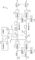
Turning now to fig. 1, a communication architecture 100 is shown that uses a parallel O-band optical transmission system, with corresponding values of signal loss (expressed in decibels (dB)). The parallel O-band architecture 100 includes a signal input 105 to a splitter 110 (e.g., a 1x32 splitter), the splitter 110 resulting in-15 dB loss. The splitter 110 splits a signal input to the semiconductor optical chip 190 at the transmitter side. Optical chip 190 (also referred to as a chiplet) includes a fiber-to-chip module 120, a modulator 130, a multiplexer 140, and a chip-to-fiber module 150. As the optical signal propagates through optical chip 190, the fiber-to-chip module 120 contributes an additional loss of-2 dB, the modulator 130 adds an additional-5 dB loss, the multiplexer 140 contributes an additional-1 dB loss, and the chip-to-fiber module 150 loses an additional-2 dB. Thus, the input signal experiences a loss of at least-25 dB even before reaching the transmission fiber 155.
Continuing, if the length of optical transmission fiber 155 is approximately 10 kilometers (10 km), then optical transmission fiber 155 causes-4 dB of additional loss before the optical signal enters semiconductor optical chip 195 at the receiving location. Receive optical chip 195 includes a fiber-to-chip module 160, a demultiplexer 170, and a receiver 180, each contributing additional losses of-2 dB, -1dB, and-10 dB, respectively. Thus, from splitter 115 (start) to receiver 180 (end), the signal experiences a total loss in excess of-30 dB.
To mitigate signal losses approaching-30 dB, a parallel O-band amplifier system 200 is shown in fig. 2. As shown in fig. 2, the system 200 includes an optical signal input 205a … 205n (collectively 205). Each optical signal input 205 can carry signals of multiple wavelengths (e.g., four (4) wavelengths, eight (8) wavelengths, etc.) using, for example, known CWDM or LAN-WDM schemes, allowing for higher data throughput.
Continuing, the system 200 includes an optional input monitor 210a … 210n (collectively 210) for monitoring the corresponding optical inputs 205, along with optional input optical isolators 215a … 215n (collectively 215), wherein the input optical isolators 215 are optically coupled to their respective inputs 205. Depending on the particular network requirements, the input monitor 210 and optical isolator 215 may be omitted to further reduce cost and complexity.
For some embodiments, the gain fiber 245 is a dispersion compensating gain fiber or a dispersion flattened gain fiber, which may be fabricated using appropriate co-dopants or different fiber geometries, as will be appreciated by those skilled in the art. By compensating for dispersion, the gain fiber can accommodate higher baud rates (e.g., greater than 50 gigabaud per second (50Gbaud/s)) and complex modulation formats (e.g., pulse amplitude modulation 4(PAM-4), PAM-8, etc.).
To pump the gain fiber 245, the system further includes a pumping unit 220 that serves as a source for P pump signals 225a … 225P (collectively 225). Importantly, there are fewer pumps 225 than gain fiber 245 (i.e., P ≦ N), thereby requiring the pump sources to provide a shared pump signal to gain fiber 245. In other words, the number of pump sources is less than the number of transmission signal sources, thereby requiring that a single pump source 225 be shared by a subset of gain fibers 245. To achieve the desired scale efficiency, in a preferred embodiment, the ratio between N and P is greater than or equal to ten (i.e., N ≧ 10P), and even more preferably greater than or equal to sixteen (i.e., N ≧ 16P). Thus, for example, N96 transmission optical channels may be efficiently pumped with six (6) or fewer pumps (i.e., P ≦ 6).
Those skilled in the art will recognize that the number of optical transmission channels may be as high as (or greater than) 128 (i.e., N ≧ 128), while the number of pump sources P may be as low as (or less than) 2 (i.e., P ≦ 2). A balance between the number of components and the performance gains from these components should be considered. For example, four (4) 100 milliwatt (mW) lasers that do not require any type of active cooling may be less expensive than a single 400mW laser that requires active cooling. Furthermore, using multiple lasers operating at the linear portion of the power-current curve (PI curve) may yield higher efficiency and lower power consumption than a single laser operating near the saturation point of the PI curve. These and other considerations are known to those skilled in the art and are therefore not discussed further herein.
It should be noted that if the gain fiber 245 is a multi-core fiber, the gain fiber 245 may be configured for either core pumping or cladding pumping. Finally, the use of a shared pump signal 225 allows massive parallel amplification in the parallel O-band amplifier system 200.
Continuing with FIG. 2, for some embodiments, the pump unit 220 includes a pump divider that generates P pump signals 225 and the necessary drive circuitry. For the bismuth-doped gain fiber 245, the pump center wavelength (λ p) of the laser diode is between-1190 nm and-1240 nm.
To allow efficient pumping, some embodiments of the pump unit 220 have a laser diode connected in parallel with a current source, allowing P pump signals 225 to be generated from a single current source. Instead of a single current source, multiple current sources may be used. The emphasis is that the current sources are shared resources (meaning that system 200 does not require N current sources), thereby reducing cost and complexity. It should be appreciated that the laser diode may be either a single laser diode or a plurality of laser diodes, either cooled or uncooled. Furthermore, the laser diode may operate as either a single mode or a multimode.
To evenly distribute the pump power, the system 200 also includes a pump equalizer that substantially equalizes the P pump signals 225. Those skilled in the art will recognize that the pump cell 220 may include a strip output for the P pump signals 225. The embodiment of fig. 2 also shows a splitter 230 (or pump splitter) that receives P pump signals 225 and splits them into N separate pump signals along N parallel paths 235a … 235N (collectively 235). It should be appreciated that splitter 230 may also be configured to act as a pump equalizer to provide P/N power evenly over the N channels (or channels) without reducing amplification in each channel (or channel). Therefore, even in the case where P ═ N, the use of an NxN splitter will improve reliability.
Alternatively, multiple pumps operating at different wavelengths may be combined by a wavelength selective combiner (e.g., a WDM combiner). In this case, in addition to power splitting, each channel also receives multiple pump wavelengths that can be used to expand or equalize the gain bandwidth in an O-band gain fiber (e.g., a bismuth-doped gain fiber).
The N parallel paths 235 are the inputs to N corresponding pump-signal combiners 240a … 240N (collectively 240). For the co-pumping scheme, in addition to receiving the N individual pump signals, the pump-signal combiner 240 also receives the optical signals concurrently (from their respective signal inputs 205). Thus, for each parallel path, the pump and signal are combined at pump-signal combiner 240 before the combined pump and signal is provided to its corresponding gain fiber 245. Similar to the input, each gain fiber 245 may also have an optional output monitor 250a … 250n (collectively 250) to monitor the amplified signal from gain fiber 245. The pump-signal combiner 240 may be a Tapered Fiber Bundle (TFB). Alternatively, the pump and signal can be coupled using side coupling. As understood by those skilled in the art, in an alternative embodiment, a counter-pumping scheme may be used.
The system 200 also includes an optical signal output 260a … 260n (collectively 260) that outputs the amplified signals in parallel. It should be appreciated that output isolator 255a … 255n (collectively 255) may optionally be interposed between gain fiber 245 and signal output 260. To the extent that system 200 operates in the O-band, signal output 260 has a λ 0 centered between 1260nm and 1360 nm.
The parallel (or arrayed) O-band system 200 can be constructed in a distributed module that can be integrated with elements of an optical switch (e.g., an optical switch having N parallel-400 Gb/s input and/or output ports, etc.), an optical router (e.g., an optical router having 400Gb/s parallel input and/or output ports), or any other type of optical transceiver. For embodiments that integrate parallel O-band amplification in an optical switch, the parallel O-band amplifier 200 may increase power at the output of the switch or at the input of the switch, or both.
Preferably, for some embodiments, the parallel O-band optical amplifier system 200 produces a receiver input gain (G) greater than about three decibels (i.e., G > -3 dB) and produces a Power Conversion Efficiency (PCE) greater than about five percent (i.e., PCE > -5%). Thus, the system 200 simultaneously amplifies multiple optical channels performed on a single fiber, a single fiber core (e.g., in a multi-core fiber), or a combination of both (e.g., multiple multi-core fibers), where each channel may carry multiple WDM channels (e.g., CWDM or LAN-WDM).
Those skilled in the art will recognize that, to be effective (and to account for typical power budgets), the disclosed parallel O-band amplifier system 200 need only provide a few dB of gain per optical channel and only a few dBm of output power. For example, a 4dB gain may be sufficient to increase the link length (or transmission distance) by 10km, with a typical receiver sensitivity of PAM-4 at 50Gbaud/s being about-4 dBm to-0 dBm. As another example, for a 10% PCE and a required output power of +0 dB/channel, the disclosed embodiments would require only 10 mW/channel of pump power. In contrast, a conventional typical Single Mode (SM) laser diode has an output power of 500mW, while a conventional multimode (MM) laser diode has an output power of 10W (a large difference compared to the requirements of the disclosed parallel O-band amplifier system 200).
Amplification of low power signals is sometimes more efficient than increasing the power of a Continuous Wave (CW) laser, even if the PCE is limited, in terms of overall power consumption. For example, if the power budget for 32 fiber channels with a total CW source power of 26dBm (400mW) is increased by 6dB, the receiver input power is correspondingly increased from-6 dBm to +0dBm for each fiber channel. In other words, the power in each fiber channel after transmission is 32dB lower than the total CW source power. Traditionally, a 6dB increase in CW source power would require a 1.2 watt (W) increase in optical power and a 4.8W increase in electrical power (assuming a wall-plug efficiency of twenty-five percent (25%) for a cooled high power laser). In contrast, assuming the disclosed parallel O-band amplifier system 200 has an efficiency of 20% PCE, the parallel O-band amplifier system 200 would require only 160mW of pump light power for a corresponding improvement. Furthermore, because uncooled pump lasers are often used for O-band communications, the parallel O-band amplifier system 200 exhibits higher wall-to-wall conversion efficiency (-50%) for electrical power of 320 mW. Even for a-5% PCE, the power consumption of the parallel O-band amplifier system 200 is reduced by a factor of 3.75 compared to a single wavelength amplifier system (e.g., a semiconductor optical amplifier or a single wavelength fiber amplifier).
Ultimately, to reduce cost, complexity, and power consumption, the sharing of components (e.g., sharing pumps) should be maximized while concurrently avoiding function doubling. Also, it would be beneficial to use ribbonized assemblies and ribbonized fibers to minimize the number of splices (splice). It should also be noted that a channel may refer to any waveguide structure, such as multiple optical fibers, multiple cores within a single optical fiber (e.g., a multicore optical fiber), or multiple multicore optical fibers.
In turn, higher capacity is often achieved by increasing the channel bit rate and WDM channel count. In other words, link capacity is typically increased by increasing fibre channel capacity or increasing the number of fibre channels. However, increasing link capacity by increasing fibre channel capacity will result in power budget limitations. Thus, in the parallel O-band amplifier system 200, providing simultaneous gain to multiple fiber channels provides a more efficient solution than that achieved in conventional amplifier systems.
For embodiments with multimode (MM) pumping and Single Mode (SM) gain fibers, a corresponding number of MM to SM transitions are required. One approach is to use a photonic lantern 300, which is shown in fig. 3A and 3B. Specifically, fig. 3A shows a lateral view of a photonic lantern 300 that converts MM signals to SM signals, while fig. 3B shows an axial view of the photonic lantern 300 (at the junction between the MM and SM sides). MM fiber 310 includes MM core 320. The MM side (at the point designated by line a-a) is joined to SM side 340. The SM side 340 includes a plurality of tapered SM cores 330a … 330n (collectively 330) allowing for the conversion of MM signals into SM signals.
Because the output power of the photonic lantern 300 is often not equal, power equalization may be necessary. One approach is to use a power equalizer 400, such as a fused (fused) coupler, which is shown in fig. 4. As shown in fig. 4, the power equalizer 400 includes a multimode pump 410, the multimode pump 410 having an optical connection 415 with a MM-to-SM coupler 420 (such as shown in fig. 3A and 3B). One (1) input 415 from MM pump 410 is converted into N coupler outputs 425. The N coupler outputs 425 are input to an N-input N-output SM coupler 430, which generates N equalized SM signals 435. Those skilled in the art will recognize that other methods of signal equalization and MM to SM conversion may be employed.
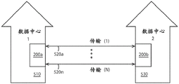
The disclosed parallel O-band system 200 may be implemented in various telecommunications, data communications systems, or non-data transmission environments. Examples of such embodiments are shown in fig. 5 and 6. In particular, fig. 5 shows a block diagram of an optical transmission system for communicating from one data center 510 to another data center 530 over long-haul optical fibers 520a … 520n (collectively 520). As shown in fig. 5, the transmission fiber 520 is optically coupled to the parallel O- band amplifier systems 200a, 200b at both the transmission end and the receiving end. With this configuration, the parallel O- band amplifier systems 200a, 200b can be used in systems requiring optical fiber transmission lengths in excess of 20km (and preferably in excess of 40 km).
Because large volumes of information are transmitted from one data center 510 to another data center 530, the transmission fiber 520 requires a large fiber count (e.g., N ≧ 96). Thus, when a capacity upgrade (e.g., increased number of channels, increased data rate, etc.) is implemented, it becomes more convenient and cost effective to upgrade silicon photonics chips with appropriate parallel O-band amplification (e.g., increased pump power, etc.) than to upgrade a large number of pluggable components. Furthermore, depending on the wavelength, modulation format and baud rate, the dispersion limit of the O-band is typically between-40 km and-120 km, and therefore the power limit (or budget) in the O-band decreases with the total link capacity. The parallel O-band amplifier system 200 accommodates these extended distances in a cost-effective manner.
For example, 400Gb/s LR-8, 25Gbaud/s PAM-4LAN-WDM systems are limited to 10km due to power. However, the corresponding dispersion limit is 50 km. Since the O-band single mode fiber loss is-4 dB/10km, the long haul transmission distance can be extended to-20 km by simply increasing the gain by-4 dB using the disclosed parallel O-band amplifier system 200. Similarly, the transmission distance can be extended to-30 km or even up to-40 km by increasing the gain by-8 dB and-12 dB, respectively. Notably, these gain values (e.g., 4dB, 8dB, or 12dB) are much lower than conventional C-band terrestrial or metropolitan links. However, even if the gain value is so low, O-band transmission can be increased by approximately four times (4 x).
One notable point is that in fig. 5, the parallel O-band amplifier system 200 is placed at a point where power is low, thereby reducing power consumption. This arrangement of the parallel O-band amplifier system 200 is contrary to conventionally accepted beliefs, as telecommunication systems are typically noise limited and therefore require sufficient signal power to avoid signal-to-noise ratio (SNR) degradation.
Before continuing, it should be appreciated that the inter-data center architecture of FIG. 5 may be implemented in a data center architecture having high data capacity requirements. Further discussion of high capacity intra-data center systems is omitted herein, so long as the system components are substantially similar between the inter-data center architecture and the intra-data center architecture.
Turning to fig. 6, a star network is shown having a central node 610 and peripheral nodes 630a … 630n (collectively 630). Unlike fig. 5, where all N transmission lines 520 are connected only between two (2) entities (i.e., one data center 510 and another data center 530), the embodiment of fig. 6 includes transmission lines 620a … 620N (collectively 620) connected from a central node 610 to a plurality of different peripheral nodes 630. In other words, the parallel O-band amplifier system 200 is used for long distance transmission to a plurality of different entities. It should be noted that having multiple peripheral nodes 630 does not preclude placing the parallel O-band amplifier system 200 in a remote node.
The parallel O-band amplifier system 200 of fig. 2 may also be configured as part of an optical subsystem, similar to an optical switch or optical router (discussed above). These types of optical switches or routers have a large number (e.g., N-128) of high capacity input ports (e.g., 400Gb/s inputs) and a large number (e.g., N-128) of high capacity output ports (e.g., 400Gb/s outputs), where each port carries multiple WDM channels (e.g., 4 to 8 channels) at very high data rates (e.g., greater than-100 Gb/s).
One approach, therefore, is to use a relatively small number of high power lasers that are divided between multiple data modulators in the silicon photonics chip, the high power lasers being located remotely (at a distance) from the silicon photonics chip. Additional parallel optical amplification per fiber may be provided with the parallel O-band amplifier system 200 due to the limitations of the output power of the laser diode, and because the combined loss of the silicon photonic chip and the fiber link may exceed-30 dB.
It should be appreciated that the pump laser can be positioned remotely (several hundred meters from the silicon photonics chip) to reduce thermal distribution problems. The gain fibers and other components may be located around the physical perimeter of the switch or router, rather than at the center of the switch or router.
For some embodiments, the pump-signal combiner may be placed on the silicon photonics chip, allowing the pump laser to be remotely located, but dividing the pump signal at the silicon photonics chip itself so that the proximity of the pump and signal is close to the transmission or reception channel (or both channels). This configuration allows the gain fiber to be coupled to either the input or the output of the silicon photonic chip.
As shown in the embodiments of fig. 2-6, sharing resources (such as, for example, pump sources) to provide parallel amplification in the O-band reduces both cost and power consumption. Thus, by using the disclosed parallel O-band amplifier system 200, previously impractical approaches (i.e., high data capacity and long range O-band communications) become commercially viable.
It should be understood that any process descriptions or blocks in flow charts may be performed out of order from that shown or discussed, including substantially concurrently or in reverse order, depending on the functionality involved, as would be understood by those reasonably skilled in the art of the present disclosure.
While exemplary embodiments have been shown and described, it will be apparent to those of ordinary skill in the art that a number of changes, modifications, or alterations to the described disclosure may be made.
For example, a single or shared dielectric pump-signal combiner may be used. Also, the pump and signal can be combined using fused components (for either a stand-alone solution or an integrated solution (meaning packaging multiple components together)). In addition, the center wavelength of fused WDM may be selected to provide gain equalization. For some embodiments, passive filters may be used for pump-signal combining. For example, a shared medium (e.g., a thin film filter) may be used to combine multiple pump-signal pairs simultaneously. In some embodiments, the pump-signal combiner can include other components, such as, for example, integrated isolators, taps, and the like. For the counter-pumping scheme, the pump and signal may be combined by an optical circulator. It should be appreciated that the pump-signal combiner can also be a ribbon assembly. For embodiments where the gain fiber exhibits a bleaching effect (PCE dependence of input signal power), both the transmitter and receiver ends may be amplified.
Accordingly, all such changes, modifications and alterations should be seen as within the scope of the present disclosure.
Claims (20)
1. A system, comprising:
an optical signal input;
n gain fibers, N being an integer greater than or equal to two (2. ltoreq.N), the gain fibers being optically coupled to corresponding optical signal input ends, each gain fiber being for receiving an optical signal from a corresponding optical signal input end;
p pump sources, P being an integer less than or equal to N (P ≦ N), each pump source optically coupled to a corresponding subset of the gain fibers, the pump sources for providing a shared pump signal to the gain fibers;
an optical signal output end optically coupled to a corresponding gain fiber; and
the operating center wavelength λ 0, λ 0 of the optical signal output is centered between about 1260 nanometers (-1260 nm) and-1360 nm to allow the system to operate in the original band (O-band).
2. The system of claim 1, wherein the system is a parallel band O-band optical amplifier comprising:
a receiver input gain (G) greater than about three decibels (G > -3 dB); and
a Power Conversion Efficiency (PCE) of greater than about five percent (PCE > -5%).
3. The system of claim 1, further comprising a pumping unit comprising:
a pump distributor including P pump sources;
a driving circuit for outputting P pumping signals; and
a pump equalizer for substantially equalizing the P pump signals.
4. The system of claim 3, the pumping unit comprising:
a current source; and
a laser diode connected in parallel with the current source; and
the pumping operation center wavelength lambdap of the laser diode is between 1190nm and 1240 nm.
5. The system of claim 3, the pump unit further comprising a ribbon output.
6. The system of claim 1, further comprising a pump splitter to split a shared pump signal from the P pump sources into N separate pump signals.
7. The system of claim 6, further comprising N pump-signal combiners, the pump-signal combiners being configured to receive corresponding pump signals, the pump-signal combiners being further configured to receive corresponding optical signals, the pump-signal combiners being further configured to combine the received pump signals with the received optical signals.
8. The system of claim 1, wherein:
n is greater than or equal to 16P (N is greater than or equal to 16P).
9. The system of claim 8, wherein:
n is greater than or equal to thirty-two (N is greater than or equal to 32); and
p is less than or equal to two (P is less than or equal to 2).
10. The system of claim 8, wherein:
n is greater than or equal to ninety-six (N is greater than or equal to 96); and
p is less than or equal to six (P is less than or equal to 6).
11. The system of claim 8, wherein:
n is greater than or equal to one hundred and twenty-eight (N > 128); and
p is less than or equal to two (P is less than or equal to 2).
12. The system of claim 1, the gain fiber being a multicore fiber.
13. The system of claim 12, the multi-core fiber configured as a core pump.
14. The system of claim 12, the multi-core fiber configured as cladding-pumped.
15. The system of claim 1, the gain fiber being ribbon-shaped.
16. The system of claim 1, further comprising:
n input optical isolators optically coupled between respective optical signal input ends and respective gain fibers; and
n output optical isolators optically coupled between the corresponding gain fibers and the corresponding optical signal output terminals.
17. The system of claim 1, further comprising:
transmission fibers, each transmission fiber optically coupled to a corresponding optical signal output; and
the transmission length of each fiber is greater than about twenty kilometers (20 km).
18. The system of claim 1, wherein the system comprises an optical switch comprising:
input ports, each input port having an input data rate of approximately four hundred gigabits (400 Gb/s) per second; and
output ports, each output port having an output data rate of 400 Gb/s.
19. The system of claim 1, wherein the system is one selected from the group consisting of:
a semiconductor optical chip;
data links between data centers;
a data link between the central network node and the peripheral node; and
an optical router.
20. The system of claim 19, wherein the optical router comprises:
input ports, each input port having an input data rate of approximately four hundred gigabits (400 Gb/s) per second; and
output ports, each output port having an output data rate of 400 Gb/s.
Applications Claiming Priority (3)
| Application Number | Priority Date | Filing Date | Title |
|---|---|---|---|
| US201962902634P | 2019-09-19 | 2019-09-19 | |
| US62/902,634 | 2019-09-19 | ||
| PCT/US2020/051623 WO2021055844A1 (en) | 2019-09-19 | 2020-09-18 | Parallel o-band amplifier |
Publications (1)
| Publication Number | Publication Date |
|---|---|
| CN114556721A true CN114556721A (en) | 2022-05-27 |
Family
ID=74884597
Family Applications (1)
| Application Number | Title | Priority Date | Filing Date |
|---|---|---|---|
| CN202080072518.XA Pending CN114556721A (en) | 2019-09-19 | 2020-09-18 | Parallel O-band amplifier |
Country Status (6)
| Country | Link |
|---|---|
| US (1) | US20220337018A1 (en) |
| EP (1) | EP4032155A4 (en) |
| JP (1) | JP2022549184A (en) |
| CN (1) | CN114556721A (en) |
| BR (1) | BR112022005222A2 (en) |
| WO (1) | WO2021055844A1 (en) |
Family Cites Families (25)
| Publication number | Priority date | Publication date | Assignee | Title |
|---|---|---|---|---|
| US5241414A (en) * | 1992-08-21 | 1993-08-31 | At&T Bell Laboratories | Fault tolerant optical amplifier arrangement |
| US6212310B1 (en) * | 1996-10-22 | 2001-04-03 | Sdl, Inc. | High power fiber gain media system achieved through power scaling via multiplexing |
| JP3165090B2 (en) * | 1997-10-30 | 2001-05-14 | 日本電気株式会社 | Light switch |
| JP2002062552A (en) * | 2000-08-18 | 2002-02-28 | Sumitomo Electric Ind Ltd | Raman amplifier and optical communication system |
| US6665320B1 (en) * | 2001-01-29 | 2003-12-16 | Lightwave Electronics | Wideband tunable laser sources with multiple gain elements |
| JP4551007B2 (en) * | 2001-02-06 | 2010-09-22 | 富士通株式会社 | Raman amplifier and optical transmission system using the same |
| US6580552B2 (en) * | 2001-08-27 | 2003-06-17 | Jds Uniphase Corporation | Shared pump and serial rare earth doped fiber optical amplifiers |
| US7075712B2 (en) * | 2002-05-30 | 2006-07-11 | Fujitsu Limited | Combining and distributing amplifiers for optical network and method |
| JP4725951B2 (en) * | 2004-07-28 | 2011-07-13 | 富士通株式会社 | Wavelength multiplexed signal light amplification method and optical amplifier |
| CN101133529A (en) * | 2005-03-04 | 2008-02-27 | 独立行政法人科学技术振兴机构 | Wide-band optical amplifier |
| US7440701B2 (en) * | 2005-12-13 | 2008-10-21 | Broadway Networks, Ltd. | Fiber-to-the-premise optical communication system |
| US7382810B2 (en) * | 2006-01-13 | 2008-06-03 | Exfo Electro-Optical Engineering, Inc. | Widely-tunable laser apparatus |
| US8441718B2 (en) * | 2009-11-23 | 2013-05-14 | Lockheed Martin Corporation | Spectrally beam combined laser system and method at eye-safer wavelengths |
| JP2014522997A (en) * | 2011-06-20 | 2014-09-08 | オーエフエス ファイテル,エルエルシー | Technologies and devices for low-loss connections to multicore fibers |
| WO2013036945A1 (en) * | 2011-09-08 | 2013-03-14 | Ofs Fitel, Llc | Arrangement for deploying co-existing gpon and xgpon optical communication systems |
| US9379512B2 (en) * | 2014-04-11 | 2016-06-28 | Ofs Fitel, Llc | Arrayed optical fiber amplifier using ribbonized erbium-doped fiber |
| JP6485189B2 (en) * | 2015-04-23 | 2019-03-20 | 富士通株式会社 | Optical transmission system and optical transmission device |
| EP3300265B1 (en) * | 2016-09-22 | 2018-12-26 | Xieon Networks S.à r.l. | Raman pumping arrangement with improved osc sensitivity |
| WO2018193587A1 (en) * | 2017-04-20 | 2018-10-25 | Nec Corporation | Optical amplifying apparatus and method of amplifying optical signal |
| WO2020056264A1 (en) * | 2018-09-13 | 2020-03-19 | Ofs Fitel, Llc | Bismuth doped fiber amplifier |
| US11824320B2 (en) * | 2019-02-22 | 2023-11-21 | Nec Corporation | Optical amplifier, and control method therefor |
| WO2021126674A1 (en) * | 2019-12-18 | 2021-06-24 | Ofs Fitel, Llc | Amplified hollow core fiber transmission |
| US11870205B2 (en) * | 2020-07-14 | 2024-01-09 | Cybel, LLC. | Efficient in-band pumping of Holmium-doped optical fiber amplifiers |
| JP2022177878A (en) * | 2021-05-19 | 2022-12-02 | 日本電気株式会社 | Optical amplifier, optical transmission system, and optical amplification method |
| US20240022038A1 (en) * | 2022-07-15 | 2024-01-18 | Electro-Optics Technology, Incorporated | Laser amplification with passive peak-power filter |
-
2020
- 2020-09-18 US US17/760,725 patent/US20220337018A1/en active Pending
- 2020-09-18 EP EP20866087.8A patent/EP4032155A4/en active Pending
- 2020-09-18 CN CN202080072518.XA patent/CN114556721A/en active Pending
- 2020-09-18 BR BR112022005222A patent/BR112022005222A2/en unknown
- 2020-09-18 WO PCT/US2020/051623 patent/WO2021055844A1/en unknown
- 2020-09-18 JP JP2022517724A patent/JP2022549184A/en active Pending
Also Published As
| Publication number | Publication date |
|---|---|
| WO2021055844A1 (en) | 2021-03-25 |
| EP4032155A4 (en) | 2023-10-25 |
| EP4032155A1 (en) | 2022-07-27 |
| BR112022005222A2 (en) | 2022-08-16 |
| JP2022549184A (en) | 2022-11-24 |
| US20220337018A1 (en) | 2022-10-20 |
Similar Documents
| Publication | Publication Date | Title |
|---|---|---|
| Benyahya et al. | Multiterabit transmission over OM2 multimode fiber with wavelength and mode group multiplexing and direct detection | |
| EP3342071B1 (en) | Multi-wavelength laser system for optical data communication links and associated methods | |
| CN100431289C (en) | Optical transmission systems using optical amplifiers and wavelength division multiplexing | |
| JP5884905B2 (en) | Optical transceiver and optical output value control method | |
| Feuer et al. | ROADM system for space division multiplexing with spatial superchannels | |
| KR20180091907A (en) | Optical Spatial Division Multiplexing for short reach distances | |
| US7158285B2 (en) | Raman amplification repeater and optical transmission system using the same | |
| Mendinueta et al. | Experimental demonstration of a 53 Tb/s coherent SDM-TDM add/drop/through optical network with time-division spatial super-channels and high-speed joint switching system | |
| EP3510709B1 (en) | Spatial division multiplexed optical communication systems and amplifiers for the same | |
| WO2001073979A1 (en) | Free-space optical wdm communication system | |
| US20040208542A1 (en) | Loss-less architecture and method for wavelength division multiplexing (WDM) optical networks | |
| JP2017118052A (en) | Wavelength multiplex optical transmitter and control method therefor | |
| CN111147961B (en) | Dual band Wavelength Division Multiplexed (WDM) link for Vertical Cavity Surface Emitting Lasers (VCSELs) | |
| CN114556721A (en) | Parallel O-band amplifier | |
| US20070297800A1 (en) | Wavelength Division Multiplexing Passive Optical Network System | |
| Townsend et al. | Towards colourless coolerless components for low power optical networks | |
| KR100454960B1 (en) | Interleaving bidirectional optcial add/drop multiplexer | |
| AT&T | Microsoft Word - SDM_ROADM_OFC2013 PD_v3_65.doc | |
| US20030030860A1 (en) | Redundant line unit monitoring architecture | |
| US20040042067A1 (en) | Apparatus and method for duplex optical transport using a co-directional optical amplifier | |
| WO2019155990A1 (en) | Optical node device | |
| EP3120471A1 (en) | Multi-span optical communications link having remote optically pumped amplifier | |
| Matsumoto et al. | Experimental demonstration of a SDM node with low power consumption MC-EDFA and SPOC-based WSS arrays | |
| Iannone et al. | Hybrid SOA-Raman amplifiers for fiber-to-the-home and metro networks | |
| JP2008244047A (en) | Optical transceiver module |
Legal Events
| Date | Code | Title | Description |
|---|---|---|---|
| PB01 | Publication | ||
| PB01 | Publication | ||
| SE01 | Entry into force of request for substantive examination | ||
| SE01 | Entry into force of request for substantive examination |