CN1145407C - Acoustic matching material, method of manufacture thereof, and ultrasonic transmitter using acoustic matching material - Google Patents
Acoustic matching material, method of manufacture thereof, and ultrasonic transmitter using acoustic matching material Download PDFInfo
- Publication number
- CN1145407C CN1145407C CNB008043922A CN00804392A CN1145407C CN 1145407 C CN1145407 C CN 1145407C CN B008043922 A CNB008043922 A CN B008043922A CN 00804392 A CN00804392 A CN 00804392A CN 1145407 C CN1145407 C CN 1145407C
- Authority
- CN
- China
- Prior art keywords
- small pieces
- acoustic matching
- matching parts
- layer
- ground floor
- Prior art date
- Legal status (The legal status is an assumption and is not a legal conclusion. Google has not performed a legal analysis and makes no representation as to the accuracy of the status listed.)
- Expired - Fee Related
Links
- 239000000463 material Substances 0.000 title claims abstract description 91
- 238000000034 method Methods 0.000 title claims description 40
- 238000004519 manufacturing process Methods 0.000 title claims description 29
- 239000011521 glass Substances 0.000 claims description 114
- 239000000203 mixture Substances 0.000 claims description 58
- 239000012530 fluid Substances 0.000 claims description 52
- RTAQQCXQSZGOHL-UHFFFAOYSA-N Titanium Chemical compound [Ti] RTAQQCXQSZGOHL-UHFFFAOYSA-N 0.000 claims description 51
- 239000010936 titanium Substances 0.000 claims description 51
- 229910052719 titanium Inorganic materials 0.000 claims description 51
- 238000002844 melting Methods 0.000 claims description 34
- 229910000679 solder Inorganic materials 0.000 claims description 31
- 239000002245 particle Substances 0.000 claims description 27
- 238000006253 efflorescence Methods 0.000 claims description 25
- 206010037844 rash Diseases 0.000 claims description 25
- BQCADISMDOOEFD-UHFFFAOYSA-N Silver Chemical compound [Ag] BQCADISMDOOEFD-UHFFFAOYSA-N 0.000 claims description 19
- 239000000843 powder Substances 0.000 claims description 19
- 229910052709 silver Inorganic materials 0.000 claims description 19
- 239000004332 silver Substances 0.000 claims description 19
- 238000010438 heat treatment Methods 0.000 claims description 14
- 230000008018 melting Effects 0.000 claims description 12
- 239000000919 ceramic Substances 0.000 claims description 10
- 230000003647 oxidation Effects 0.000 claims description 8
- 238000007254 oxidation reaction Methods 0.000 claims description 8
- 230000013011 mating Effects 0.000 claims description 5
- 238000003466 welding Methods 0.000 claims description 5
- 238000003763 carbonization Methods 0.000 claims description 4
- 229910010293 ceramic material Inorganic materials 0.000 claims description 4
- 229910001220 stainless steel Inorganic materials 0.000 description 17
- 239000010935 stainless steel Substances 0.000 description 17
- 229920005989 resin Polymers 0.000 description 15
- 239000011347 resin Substances 0.000 description 15
- 238000005476 soldering Methods 0.000 description 14
- 239000007789 gas Substances 0.000 description 13
- 239000004579 marble Substances 0.000 description 13
- 238000005259 measurement Methods 0.000 description 12
- XLYOFNOQVPJJNP-UHFFFAOYSA-N water Chemical compound O XLYOFNOQVPJJNP-UHFFFAOYSA-N 0.000 description 12
- PNEYBMLMFCGWSK-UHFFFAOYSA-N aluminium oxide Inorganic materials [O-2].[O-2].[O-2].[Al+3].[Al+3] PNEYBMLMFCGWSK-UHFFFAOYSA-N 0.000 description 9
- 230000015572 biosynthetic process Effects 0.000 description 9
- 230000008859 change Effects 0.000 description 9
- 238000005516 engineering process Methods 0.000 description 9
- 230000008569 process Effects 0.000 description 8
- 238000012546 transfer Methods 0.000 description 8
- 239000012153 distilled water Substances 0.000 description 7
- GWEVSGVZZGPLCZ-UHFFFAOYSA-N Titan oxide Chemical compound O=[Ti]=O GWEVSGVZZGPLCZ-UHFFFAOYSA-N 0.000 description 6
- 238000009434 installation Methods 0.000 description 6
- OGIDPMRJRNCKJF-UHFFFAOYSA-N titanium oxide Inorganic materials [Ti]=O OGIDPMRJRNCKJF-UHFFFAOYSA-N 0.000 description 6
- 230000005540 biological transmission Effects 0.000 description 5
- 239000007767 bonding agent Substances 0.000 description 5
- 239000003795 chemical substances by application Substances 0.000 description 5
- 229910052751 metal Inorganic materials 0.000 description 5
- 239000002184 metal Substances 0.000 description 5
- 239000000047 product Substances 0.000 description 5
- 230000005855 radiation Effects 0.000 description 5
- IJGRMHOSHXDMSA-UHFFFAOYSA-N Atomic nitrogen Chemical compound N#N IJGRMHOSHXDMSA-UHFFFAOYSA-N 0.000 description 4
- 230000000694 effects Effects 0.000 description 4
- 239000003822 epoxy resin Substances 0.000 description 4
- 238000010237 hybrid technique Methods 0.000 description 4
- 229920000647 polyepoxide Polymers 0.000 description 4
- 238000001556 precipitation Methods 0.000 description 4
- 238000006681 Combes synthesis reaction Methods 0.000 description 3
- 239000004809 Teflon Substances 0.000 description 3
- 229920006362 Teflon® Polymers 0.000 description 3
- NRTOMJZYCJJWKI-UHFFFAOYSA-N Titanium nitride Chemical compound [Ti]#N NRTOMJZYCJJWKI-UHFFFAOYSA-N 0.000 description 3
- QVGXLLKOCUKJST-UHFFFAOYSA-N atomic oxygen Chemical compound [O] QVGXLLKOCUKJST-UHFFFAOYSA-N 0.000 description 3
- 230000007797 corrosion Effects 0.000 description 3
- 238000005260 corrosion Methods 0.000 description 3
- 230000008878 coupling Effects 0.000 description 3
- 238000010168 coupling process Methods 0.000 description 3
- 238000005859 coupling reaction Methods 0.000 description 3
- 238000009826 distribution Methods 0.000 description 3
- 239000000945 filler Substances 0.000 description 3
- 238000002156 mixing Methods 0.000 description 3
- 229910052760 oxygen Inorganic materials 0.000 description 3
- 239000001301 oxygen Substances 0.000 description 3
- 239000004372 Polyvinyl alcohol Substances 0.000 description 2
- NINIDFKCEFEMDL-UHFFFAOYSA-N Sulfur Chemical compound [S] NINIDFKCEFEMDL-UHFFFAOYSA-N 0.000 description 2
- 239000005864 Sulphur Substances 0.000 description 2
- 230000001186 cumulative effect Effects 0.000 description 2
- 230000006866 deterioration Effects 0.000 description 2
- 238000001035 drying Methods 0.000 description 2
- 230000005611 electricity Effects 0.000 description 2
- 230000008020 evaporation Effects 0.000 description 2
- 238000001704 evaporation Methods 0.000 description 2
- 230000007246 mechanism Effects 0.000 description 2
- 239000000155 melt Substances 0.000 description 2
- 229910052757 nitrogen Inorganic materials 0.000 description 2
- 229920002451 polyvinyl alcohol Polymers 0.000 description 2
- 230000000644 propagated effect Effects 0.000 description 2
- 230000001902 propagating effect Effects 0.000 description 2
- 238000003756 stirring Methods 0.000 description 2
- OKTJSMMVPCPJKN-UHFFFAOYSA-N Carbon Chemical compound [C] OKTJSMMVPCPJKN-UHFFFAOYSA-N 0.000 description 1
- 241001391944 Commicarpus scandens Species 0.000 description 1
- RYGMFSIKBFXOCR-UHFFFAOYSA-N Copper Chemical compound [Cu] RYGMFSIKBFXOCR-UHFFFAOYSA-N 0.000 description 1
- 238000013459 approach Methods 0.000 description 1
- 239000011324 bead Substances 0.000 description 1
- 230000008901 benefit Effects 0.000 description 1
- 238000004364 calculation method Methods 0.000 description 1
- 229910052799 carbon Inorganic materials 0.000 description 1
- 230000008602 contraction Effects 0.000 description 1
- 229910052802 copper Inorganic materials 0.000 description 1
- 239000010949 copper Substances 0.000 description 1
- 239000005357 flat glass Substances 0.000 description 1
- 239000012634 fragment Substances 0.000 description 1
- 238000007499 fusion processing Methods 0.000 description 1
- 239000000156 glass melt Substances 0.000 description 1
- 230000005484 gravity Effects 0.000 description 1
- 230000006872 improvement Effects 0.000 description 1
- 239000012535 impurity Substances 0.000 description 1
- 239000011810 insulating material Substances 0.000 description 1
- 230000001788 irregular Effects 0.000 description 1
- 239000011159 matrix material Substances 0.000 description 1
- 230000010358 mechanical oscillation Effects 0.000 description 1
- 239000007769 metal material Substances 0.000 description 1
- 239000004033 plastic Substances 0.000 description 1
- 229920003023 plastic Polymers 0.000 description 1
- 238000005498 polishing Methods 0.000 description 1
- 239000002244 precipitate Substances 0.000 description 1
- 238000003825 pressing Methods 0.000 description 1
- 230000001737 promoting effect Effects 0.000 description 1
- 230000009467 reduction Effects 0.000 description 1
- 238000007789 sealing Methods 0.000 description 1
- 229910052717 sulfur Inorganic materials 0.000 description 1
- 238000012360 testing method Methods 0.000 description 1
- 239000010930 yellow gold Substances 0.000 description 1
- 229910001097 yellow gold Inorganic materials 0.000 description 1
Images


Classifications
-
- G—PHYSICS
- G10—MUSICAL INSTRUMENTS; ACOUSTICS
- G10K—SOUND-PRODUCING DEVICES; METHODS OR DEVICES FOR PROTECTING AGAINST, OR FOR DAMPING, NOISE OR OTHER ACOUSTIC WAVES IN GENERAL; ACOUSTICS NOT OTHERWISE PROVIDED FOR
- G10K11/00—Methods or devices for transmitting, conducting or directing sound in general; Methods or devices for protecting against, or for damping, noise or other acoustic waves in general
- G10K11/02—Mechanical acoustic impedances; Impedance matching, e.g. by horns; Acoustic resonators
-
- H—ELECTRICITY
- H04—ELECTRIC COMMUNICATION TECHNIQUE
- H04R—LOUDSPEAKERS, MICROPHONES, GRAMOPHONE PICK-UPS OR LIKE ACOUSTIC ELECTROMECHANICAL TRANSDUCERS; DEAF-AID SETS; PUBLIC ADDRESS SYSTEMS
- H04R1/00—Details of transducers, loudspeakers or microphones
- H04R1/20—Arrangements for obtaining desired frequency or directional characteristics
- H04R1/22—Arrangements for obtaining desired frequency or directional characteristics for obtaining desired frequency characteristic only
- H04R1/28—Transducer mountings or enclosures modified by provision of mechanical or acoustic impedances, e.g. resonator, damping means
- H04R1/2869—Reduction of undesired resonances, i.e. standing waves within enclosure, or of undesired vibrations, i.e. of the enclosure itself
- H04R1/2876—Reduction of undesired resonances, i.e. standing waves within enclosure, or of undesired vibrations, i.e. of the enclosure itself by means of damping material, e.g. as cladding
- H04R1/288—Reduction of undesired resonances, i.e. standing waves within enclosure, or of undesired vibrations, i.e. of the enclosure itself by means of damping material, e.g. as cladding for loudspeaker transducers
-
- H—ELECTRICITY
- H04—ELECTRIC COMMUNICATION TECHNIQUE
- H04R—LOUDSPEAKERS, MICROPHONES, GRAMOPHONE PICK-UPS OR LIKE ACOUSTIC ELECTROMECHANICAL TRANSDUCERS; DEAF-AID SETS; PUBLIC ADDRESS SYSTEMS
- H04R17/00—Piezoelectric transducers; Electrostrictive transducers
Abstract
An acoustic matching material (1) is used to match the acoustic impedance of a first object to that of a sound object when sound is transmitted from the first object to the second object. The acoustic matching material (1) includes a plurality of minute pieces (2), at least one of which is coupled to another piece (2) to form a gap in the acoustic matching material (1).
Description
(1) technical field
The present invention relates to a kind of from an object when another object transmits sound, be used for mating the acoustic matching parts of two object acoustic impedances, a kind of ultrasonic wave transmitting and receiving apparatus that is used to make the method for these acoustic matching parts and utilizes these acoustic matching parts.
(2) background technology
Obtain the acoustic impedance of an object by (density * velocity of sound).The acoustic impedance Z of air
AIRApproximately be 428kg/m
2S, and be used to produce the acoustic impedance Z of hyperacoustic piezoelectric vibrator
PZTApproximately be 30 * 106kg/m
2S.
When ultrasonic wave when the piezoelectric vibrator radiation enters air, the acoustic impedance Z of piezoelectric vibrator
PZTAcoustic impedance Z with air
AIRBetween difference cause sound reflecting, thereby reduced the radiation efficiency of sound.
The acoustic matching parts are used for by coupling piezoelectric vibrator acoustic impedance Z
PZTWith the air-borne sound impedance Z
AIRRelax the reduction of acoustic radiating efficient.
By the acoustic impedance Z that obtains the acoustic matching parts according to the expression formula (1) of Theoretical Calculation
M
Here, Z
MValue is an ideal value that does not have sound reflecting.Utilize above-mentioned Z
PZTAnd Z
AIRValue, Z
MValue approximately is 0.11 * 10
6Kg/m
2S.
Figure 29 shows the acoustic impedance of acoustic matching parts and enters relation between the acoustic energy ratio (transfer ratio) of air from the piezoelectric vibrator radiation.Should be appreciated that from Figure 29 the acoustic impedance when the acoustic matching parts approximately is 0.11 * 10
6Kg/m
2During s, under the condition that does not have sound reflecting, transfer ratio is 1.
In order to obtain having the acoustic matching parts of this desirable acoustic impedance, need to select to have low-density and allow the material of the low velocity of sound to be used for this acoustic matching parts.
Figure 30 represents an example of traditional acoustic matching parts.The mixture that is synthesized by hybrid glass ball in resin material 120 121 and curing obtains acoustic matching parts shown in Figure 30.
This glass marble is a hollow, therefore has the very light characteristics of weight.The structure that the mixture that is synthesized by hybrid glass ball in resin material and curing obtains is compared with the structure that obtains by a curing resin material, has less density.The size of glass marble be configured to the value more much smaller than the wavelength of the vibration (sound) that transmits by the acoustic matching parts (approximately be vibration wavelength 1/10 or still less).It is the influence that still less is subjected to glass marble for the propagation that makes vibration that the size of glass marble is set to such value.
At actual density is 0.13g/cm
3The glass marble (" Scotchlight of Sumitomo 3M Co., Ltd
TMGlass envelope filler ") is blended in the velocity of sound that allows about 2300m/s and has in the resin material of density of 1.2g/cm3, and when solidifying the mixture that is synthesized, having obtained density is 0.56g/cm
3With the velocity of sound that allows be the structure of 2100m/s.The acoustic impedance Z of the structure that so obtains
COMBe 1.18 * 10
6Kg/m
2S.
The open No.2-177799 of Japan Patent has described the acoustic matching parts of the glass marble formation of only using hollow.These acoustic matching parts are to make like this, are about to hollow ball and are heated to a temperature that the sky glass marble is softened, and compress this hollow ball, and a plurality of hollow ball are joined together at each contact point.Can use the Scotohlight of Sumitomo 3M Co., Ltd
TMThe glass envelope filler is as the glass marble of hollow.It is 900m/s harmony impedance Z that the acoustic matching parts that the open No.2-177799 of Japan Patent has described manufacturing like this have the velocity of sound
BGBe approximately 0.45 * 10
6Kg/m
2The characteristic of s.Because with the acoustic impedance of an object of (velocity of sound * density) expression, so the density of these acoustic matching parts is 0.5g/cm
3
As mentioned above, the velocity of sound that glass allowed is 5000 to 6000m/s, and the velocity of sound that the acoustic matching parts are allowed is owing to the glass marble that has utilized hollow in manufacture process is reduced to 900m/s.
The acoustic matching parts can utilize the bonding agent that forms by the resin material such as epoxy resin and join a vibrator to or box that one is held vibrator on.The open No.2-177799 of Japan Patent has described an example, is about to the temperature that a plurality of hollow ball are heated to softening a plurality of hollow ball, and arrives vibrator at contact point separately in conjunction with a plurality of hollow ball and with the acoustic matching part bonding.By this joint method, only form this acoustic matching parts by glass, therefore have the temperature characterisitic that is better than utilizing the acoustic matching parts that resin material forms.Reason is that the coefficient of thermal expansion of glass is lower than the coefficient of thermal expansion of resin material.When the flow velocity of gas utilized the ultrasonic wave transmitting and receiving apparatus to measure, the temperature characterisitic of ultrasonic wave transmitting and receiving apparatus significantly impacted certainty of measurement.In order accurately to measure very little gas flow rate, the temperature characterisitic of ultrasonic wave transmitting and receiving apparatus must be very little.
The gas of some types is volatile.The vibrator that needs this gas to be offered the signal of telecommunication need be contained in the box, contacts this gas to prevent vibrator.The gratifying condition of this cassette material comprises anti-high strength and the gratifying temperature characterisitic of damaging.For this reason, the material of box metal preferably.The coefficient of thermal expansion of metal is different from the coefficient of thermal expansion of glass.Therefore, in the method that day disclosure 2-177799 describes, after a plurality of hollow ball were heated to the temperature of softening a plurality of hollow ball, can harmony matching block was separated from each other, and can not combine in separately the contact point stage in conjunction with a plurality of hollow ball,
Acoustic impedance Z when above-mentioned acoustic matching material
BGAnd Z
COMWhen being plotted in Figure 29, Z
BGBe positioned at ▲, Z
COMBe positioned at ■.Transfer ratio is for Z
BGBe 0.21, for Z
COMBe 0.05.Therefore, Z
BGTransfer ratio (that is, transfer voice than) be Z
COMFour times of transfer ratio.But in fact, can not get output, but output is for Z greater than four times
BGAnd Z
COMIt is the identical order of magnitude.Because when sound transmits through out-of-date Z
BGStructure compares Z
COMThe easier sound attenuating that makes of structure this situation occurs so consider meeting.By contrast, transmit through out-of-date Z when sound
COMStructure is difficult for causing sound attenuating, and allows to compare Z
BGThe velocity of sound that structure is higher.Therefore, Z
COMStructure has bigger acoustic impedance and compares Z
BGStructure causes that more the sound reflection that radiation enters air returns.
Therefore, there is not marked difference in the voice output of the acoustic matching parts of both types.Therefore, need provide the acoustic matching parts of loud noise output rather than by Z
BGOr Z
COMThe acoustic matching parts that structure forms.Z
BGStructure cause sound significantly a possible cause of decay be the hollow ball that only engages at contact point separately and so the contact point sum relative less.
As mentioned above, traditional ultrasonic wave transmitting and receiving apparatus has following point.
The first, when forming the acoustic matching parts with resin material, the certainty of measurement of ultrasonic wave transmitting and receiving apparatus is unsatisfactory owing to the temperature characterisitic of resin material.
The second, when only forming the acoustic matching parts by empty glass marble, sound is significantly decayed owing to a small amount of contact point of hollow ball.
The 3rd, when vibrator is contained in the can when preventing vibrator contact gas, the bonding agent of using the resin material such as epoxy resin to form will worsen the certainty of measurement of ultrasonic wave transmitting and receiving apparatus with the acoustic matching part bonding owing to the temperature characterisitic of this bonding agent to can.
The 4th, after a plurality of hollow ball are heated to the temperature of softening a plurality of hollow ball, because can is different with the coefficient of thermal expansion as the glass of hollow ball material, can harmony matching block is separated from each other, and can not combine in separately the contact point stage in conjunction with a plurality of hollow ball.Even when jointing metal box harmony matching block, also can produce deflection (flexure), the therefore vibration of not propagating vibrator.
The present invention has solved first to the 4th problem.
(3) summary of the invention
Acoustic matching parts according to the present invention are used at sound mating the acoustic impedance of first object and the acoustic impedance of second object when first object propagates into second object.These acoustic matching parts comprise a plurality of small pieces.In a plurality of small pieces at least one in contact portion and a plurality of small pieces another engages at least, in the acoustic matching parts, to form the gap.
Each of a plurality of small pieces all has unbodied three-dimensional structure.
Place a plurality of small pieces and pass through acoustic matching parts linear propagation to prevent sound.
In a plurality of small pieces each is made of glass or ceramic data.
A kind of method that produces the acoustic matching parts according to the present invention, described acoustic matching parts are used at sound mating the acoustic impedance of first object and the acoustic impedance of second object when first object propagates into second object.The method comprising the steps of, and (a) forms a plurality of small pieces, (b) a plurality of small pieces are heated to the temperature of softening a plurality of small pieces, thereby contact portion make in a plurality of small pieces at least one with a plurality of small pieces in another engages at least, in the acoustic matching parts, to form the gap.
Step (b) applies the step of load on a plurality of small pieces when can be included in a plurality of small pieces of heating.
Step (a) can comprise mixes a plurality of small pieces and fluid; Step with evaporative fluid from the mixture of a plurality of small pieces and fluid.
The proportion of this fluid can be less than the proportion of a plurality of small pieces.
This fluid can evaporation after a plurality of small pieces are deposited in the fluid.
Form a plurality of small pieces by a plurality of hollow ball of efflorescence.
Come the density of guide sound matching block according to the efflorescence degree of a plurality of hollow ball.
The efflorescence degree of a plurality of hollow ball can be represented with the ratio of the volume of a plurality of small pieces that obtain after the volume before a plurality of hollow ball efflorescence and a plurality of hollow ball efflorescence.
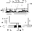
According to ultrasonic wave transmitting and receiving apparatus involving vibrations device of the present invention; The can that holds this vibrator; The acoustic matching parts of the acoustic impedance of the fluid that is used to mate the vibrator acoustic impedance and flows in the can outside; With the attachment that are used to engage acoustic matching parts and can.The acoustic matching parts comprise a plurality of small pieces, and in a plurality of small pieces at least one in contact portion and a plurality of small pieces another engages at least, in the acoustic matching parts, to form the gap.These attachment have the structure that is used to reduce difference between the can coefficient of thermal expansion harmony matching block coefficient of thermal expansion.
These attachment can be included in the ground floor that forms on the can, at the second layer that forms on the ground floor and the 3rd layer of forming on the second layer.Ground floor can be formed by silver solder.The second layer can be formed by titanium.The 3rd layer can be formed by silver solder.
These attachment can further include the 4th layer and the layer 5 that forms in formation on the 3rd layer on the 4th layer.The 4th layer can be ceramic wafer or glass plate.Layer 5 can be formed by the glass that fusing point is lower than the 4th layer material fusing point.
These attachment can be included in the ground floor that forms on the can, and form ground floor on the basis of the mixture that obtains by combined silver welding powder and titanium valve.
These attachment can be included in the ground floor that forms on the can, and by the combined silver welding powder, form ground floor on the basis of titanium valve and ceramic powders and the mixture that obtains.
These attachment can be included in ground floor that forms on the can and the second layer that forms on ground floor, and the composition surface between the ground floor and the second layer can have concaveconvex shape.
Ground floor can form on can off and on.
Ground floor can comprise that a plurality of coefficient of thermal expansions are lower than the particle of ground floor material heat expansion rate.
These attachment can be included in ground floor that forms on the can and the second layer that forms on ground floor.The mixture that comprises second particle of first particle of first material and second material by heating forms ground floor, wherein said first material is easy to oxidation, nitrogenize or carbonization, and the proportion of second material is greater than the proportion of first material, fusing point is lower than the fusing point of first material, and ground floor forms second material layer.The second layer can form on second material layer, and the second layer forms oxidation, nitrogenize or carbonization first material and one deck of obtaining.
The first material coefficient of thermal expansion rate is lower than the second material coefficient of thermal expansion rate.
Can and be higher than this mixture of heating under the temperature of second material melting point at the fusing point that is lower than first material.
First particle can have 150 μ m or littler size.
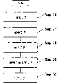
(4) description of drawings
Fig. 1 is the cross-sectional view of the acoustic matching parts 1 of first example according to the present invention.
Fig. 2 is the cross-sectional view of the acoustic matching parts 5 of second example according to the present invention.
Fig. 3 is the cross-sectional view of the acoustic matching parts 7 of the 3rd example according to the present invention.
Fig. 4 represents to be used to measure the structure of measurement mechanism of the voice output of acoustic matching parts.
Fig. 5 represents that working as acoustic impedance is Z
COMTraditional acoustic matching parts resulting measurement result as the time with tested acoustic matching parts 11.
Fig. 6 represents that working as acoustic impedance is Z
DVEAcoustic matching parts 7 resulting measurement result as with tested acoustic matching parts 11 time.
Fig. 7 represents the topology example of the manufacturing installation of the 4th example according to the present invention.
Fig. 8 is that explanation utilizes manufacturing installation shown in Figure 7 to make the flow chart of the procedure of acoustic matching parts.
Fig. 9 is by solidifying the cross-sectional view of the acoustic matching parts 30 that one group of small pieces 21 forms.
Figure 10 represents the manufacture method of the 5th example according to the present invention.
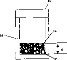
Figure 11 represents the method for a plurality of small pieces of formation of the 6th example according to the present invention.
Figure 12 represents the method for a plurality of small pieces of formation of the 6th example according to the present invention.
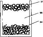
Figure 13 represents to distinguish the method for the little hollow ball 31 of not efflorescence from small pieces 34.
Figure 14 A represents the shape of resulting small pieces 34 when h2/h1=0.5.
Figure 14 B represents the shape of resulting small pieces 34 when h2/h1=0.33.
Figure 14 C represents the shape of resulting small pieces 34 when h2/h1=0.2.
Figure 15 represents the relation of h2/h1 and acoustic matching component density, and the relation between h2/h1 and the sound attenuating rate.
Figure 16 represents to utilize resulting a plurality of small pieces 34 when h2/h1=0.33 and the profile of the acoustic matching parts that form.
Figure 17 represents the topology example of the ultrasonic wave transmitting and receiving apparatus of the 7th example according to the present invention.
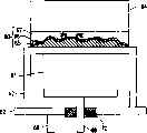
Figure 18 represents the topology example of attachment 52.
Figure 19 represents another topology example of attachment 52.
Figure 20 represents another topology example of attachment 52.
Figure 21 represents another topology example of attachment 52.
Figure 22 represents the topology example of the ultrasonic wave transmitting and receiving apparatus of the 8th example according to the present invention.
Figure 23 represents another topology example of the ultrasonic wave transmitting and receiving apparatus of the 8th example according to the present invention.
Figure 24 represents another topology example of the ultrasonic wave transmitting and receiving apparatus of the 8th example according to the present invention.
Figure 25 represents another topology example of the ultrasonic wave transmitting and receiving apparatus of the 8th example according to the present invention.
Figure 26 is the flow chart of explanation joint method process of the 9th example according to the present invention.
Figure 27 represents according to process shown in Figure 26, the profile of the major part by engaging the ultrasonic wave transmitting and receiving apparatus that acoustic matching parts 64 and can 62 make.
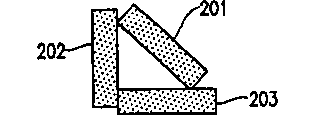
Figure 28 A represents the example of small pieces 2 (small pieces 201 to 203) contact condition, is used for forming the gap at acoustic matching parts 1.
Figure 28 B represents the example of small pieces 2 (small pieces 204 to 207) contact condition, is used for forming the gap at acoustic matching parts 1.
Figure 28 C represents the example of small pieces 2 (small pieces 208 to 212) contact condition, is used for forming the gap at acoustic matching parts 1.
Figure 29 is the acoustic impedance of explanation acoustic matching parts and the graph of a relation between the acoustic energy ratio from the air radiation to the piezoelectric vibrator (transfer ratio).
Figure 30 represents a topology example of traditional acoustic matching parts.
(5) embodiment
Hereinafter, example of the present invention is described with reference to the accompanying drawings.
(example 1)
Fig. 1 represents the profile of the acoustic matching parts 1 of first example according to the present invention.Acoustic matching parts 1 are added on the vibrator 3.
Acoustic matching parts 1 are used for mating the acoustic impedance of first object and the acoustic impedance of second object when sound propagates into second object (for example, air) from first object (for example, vibrator 3).
This acoustic matching parts 1 comprise a plurality of small pieces 2.Each of a plurality of small pieces 2 has planar structure.In a plurality of small pieces 2 each engages with another small pieces 2 at least in contact portion.
Contact can be point-to-point contact, Line To Line contact or contact face-to-face.Needed is to form the gap by being bonded with each other of a plurality of small pieces 2 in acoustic matching parts 1.By placing small pieces 2 as shown in Figure 1 brokenly, can in acoustic matching parts 1, form the gap.
Figure 28 A is used to form the gap in the acoustic matching parts 1 to the example that 28C represents small pieces 2 (small pieces 201 to 212) contact condition.
In the example shown in Figure 28 A, small pieces 201 and 202 states that are in contact with one another with the plane of a jiao of small pieces 201 and small pieces 202 are bonded together.Small pieces 201 and 203 states that are in contact with one another with the plane of another angles of small pieces 201 and small pieces 203 are bonded together.Small pieces 202 and 203 with the length of long plane of the length of small pieces 202 and small pieces 203 state of short plane contact engage together.Therefore, form the gap by the small pieces 201 of being bonded with each other to 203.
In the example shown in Figure 28 B, small pieces 204 to 207 are bonded with each other with a kind of like this state, i.e. the plane of small pieces 204 to 207 part contact each other.Therefore, form the gap by the small pieces 204 of being bonded with each other to 207.
In the example shown in Figure 28 C, small pieces 208 to 212 are bonded with each other with a kind of like this state, i.e. the plane of small pieces 208 to 212 part contact each other.Therefore, form the gap by the small pieces 208 of being bonded with each other to 212.
Even when small pieces 2 have flat shape, also can in acoustic matching parts 1, form the gap by being bonded with each other of a plurality of small pieces 2.In this case, have irregular size, can form the gap at an easy rate by placing small pieces 2 brokenly and small pieces 2 being formed.Contact between the small pieces 2 can be point-to-point contact, Line To Line contact or contact face-to-face.
Place a plurality of small pieces 2 so that acoustic matching parts 1 linear propagation is not passed through in the vibration of vibrator 3 (sound).Therefore, propagation path 4 is not linear but wriggles.As a result, sound is lower than the intrinsic velocity of sound that material allowed of small pieces 2 by total speed of the propagation of the propagation path in the acoustic matching parts 1.
For example, when small pieces 2 are formed by glass, have the velocity of sound that the acoustic matching parts 1 of structure shown in Figure 1 are allowed and be lower than the intrinsic velocity of sound 5000m/s that glass allows.Because acoustic matching parts 1 have gap shown in Figure 1, the density of acoustic matching parts 1 is starkly lower than the density of object identical with small pieces 2 size and that formed by same material.Because represent the acoustic impedance of an object with (density * velocity of sound), thereby the acoustic impedance of these acoustic matching parts 1 can be littler.
As the material of small pieces 2, for example can use plastics, metal, glass or ceramic material.
If the vibration frequency of vibrator 3 is υ, the velocity of sound is C, and then the wavelength X of sound is represented by expression formula (2).
λ=C/ υ ... expression formula (2)
Here, velocity of sound C represents that sound passes through the speed that acoustic matching parts 1 are propagated.Now hypothesis acoustic matching parts 1 are formed by a glass.Because the velocity of sound that glass allowed approximately is 5000m/s, so when the vibration frequency υ of vibrator 3 was 500kHz, the wavelength X of sound was 10mm.When acoustic matching parts 1 formed the condensate of glass small pieces 2, the velocity of sound that acoustic matching parts 1 are allowed was lower than the velocity of sound 500m/s that glass allows.For example, if the velocity of sound that acoustic matching parts 1 are allowed is 1000m/s, then the wavelength X of sound is 2mm when υ is 500kHz.
In order to make the gap that forms in the acoustic matching parts 1 littler to the influence of sound transmission, the size in gap must be fully littler than the wavelength that will transmit sound.For the size that makes the gap is equal to or less than 200 μ m, promptly wavelength of sound 1/10, and the length of each small pieces 2 is 200 μ m or littler preferably.In order to reduce the density of acoustic matching parts 1, small pieces 2 preferably have littler thickness, and for example the glass plate that preferably is approximately 1 μ m by thickness forms.
In first example, all small pieces 2 that are included in the acoustic matching parts 1 need not engage with another small pieces 2 in contact portion.That is, acoustic matching parts 1 can comprise the small pieces 2 that do not engage with another small pieces 2.As long as being included in a plurality of small pieces 2 in the acoustic matching parts at least one engages just can provide at contact portion and another small pieces 2 at least and is similar to above-mentioned effect.
(example 2)
Fig. 2 represents the profile of the acoustic matching parts 5 of second example according to the present invention.
This acoustic matching parts 5 comprise a plurality of small pieces 6.In a plurality of small pieces 6 at least one in contact portion and a plurality of small pieces 6 another engages at least, in acoustic matching parts 5, to form the gap.
In second example, each in a plurality of small pieces 6 has the structure of a plurality of projectioies.The projection of small pieces 6 contacts another small pieces 6, and small pieces 6 are in contact with one another in contact portion.Therefore, can around projection, form the gap.By making each small pieces 6 have a plurality of projectioies, two adjacent small pieces 6 can be in contact with one another in a plurality of contact portions.In this way, compare in the situation that a contact portion engages, can increase bond strength with small pieces 6.
Can on a thin plate or cube, provide these projectioies.In these cases, can also around the projection of small pieces 6, form the gap.As a result, can reduce the density of acoustic matching parts 5 at an easy rate.
Contact between the small pieces 6 can be point-to-point contact, Line To Line contact or contact face-to-face.
The operation of acoustic matching parts 5 and function class are similar to the operation and the function of the described acoustic matching parts 1 of first example.The preferably aforesaid 200 μ m or littler of the size of small pieces 6.
(example 3)
Fig. 3 represents the profile of the acoustic matching parts 7 of the 3rd example according to the present invention.This acoustic matching parts 7 comprise a plurality of small pieces 8.In a plurality of small pieces 8 at least one in contact portion and a plurality of small pieces 8 another engages at least, in acoustic matching parts 7, to form the gap.
In the 3rd example, each in a plurality of small pieces 8 is the thin plate with amorphous concaveconvex structure.Like this, each in a plurality of small pieces 8 all has unbodied three-dimensional structure.By contacting the protruding of small pieces 8 or the one end being contacted with another small pieces 8, can around contact portion, form the gap at an easy rate.By making each small pieces 8 have bossing and recessed portion, two adjacent small pieces 8 can be in contact with one another in a plurality of contact portions.In this way, compare in the situation that a contact portion engages, can increase bond strength with small pieces 8.The number of bossing and recessed portion is not limited to any concrete value.
Contact between the small pieces 8 can be point-to-point contact, Line To Line contact or contact face-to-face.
The operation of acoustic matching parts 7 and function class are similar to the operation and the function of the acoustic matching parts of describing 1 in first example.The preferably aforesaid 200 μ m or littler of the bossing of small pieces 8 and the size of recessed portion.Small pieces 8 with convex-concave structure are the minimum as far as possible plate of thickness preferably.The thickness of small pieces 8 preferably approximately is 1 μ m, to reduce the density of acoustic matching parts 7.
For example, when small pieces 8 were formed by glass, by a plurality of small pieces 8 being heated to the temperature of soften glass, a plurality of small pieces 8 can be bonded with each other.
By small pieces 8 being heated to the softening point of glass, can prevent to destroy the concaveconvex structure of small pieces 8.In the contact portion of small pieces 8, softening glass small pieces are bonded with each other.
By on small pieces 8, applying one than light load simultaneously, can strengthen the joint of small pieces 8 in contact portion at heating small pieces 8.Reason is that small pieces 8 soften by heating and pressurization.
When the load on the increase small pieces 8, small pieces 8 are out of shape under pressure, do not eliminate concaveconvex structure simultaneously.In this case, owing to load has increased contact area between the small pieces 8 and the bond strength that has increased contact portion.Like this, can reduce the decay of the sound of propagating by the contact portion of small pieces 8.
As mentioned above, can adjust bond strength between the small pieces 8 according to being applied to load on the small pieces 8.But when small pieces 8 being applied load, the density of acoustic matching parts 7 increases.As a result, increased the acoustic impedance of acoustic matching parts 7.
Acoustic matching parts 7 shown in Figure 3 are by applying 415g/cm under 700 ℃ the temperature on the condensate of small pieces 8
3Load and the structure that forms, described small pieces 8 have by big about 700 ℃ of formed concaveconvex structures of softening glass.This structure has about 0.537g/cm
3Density, allow the velocity of sound of about 1224m/s, and have 0.657 * 10
6Kg/m
2The acoustic impedance Z of s
DVEIn Figure 29, use ● drawn acoustic impedance Z
DVEAcoustic impedance Z
DVEBe in the acoustic impedance Z that " background technology " part is described
BGAnd Z
COMBetween.For the amplitude of the actual sound transmission, utilize measurement mechanism shown in Figure 4 to measure the voltage of the ultrasonic sensor of receiving terminal.
As shown in Figure 4, the acoustic matching parts 11 that test are added on the ultrasonic wave transmitter 10.The acoustic matching parts 12 of standard are added on the ultrasonic wave receiving equipment 13.
Fig. 5 represents that working as the acoustic impedance of describing with reference to Figure 30 is Z
COMTraditional acoustic matching parts resulting measurement result as the time with tested acoustic matching parts 11.Among Fig. 5, (a) expression is from the voltage waveform of signal source 9, and (b) voltage waveform (that is the output waveform of ultrasonic wave receiving equipment 13) at expression resistance 14 two ends.
Fig. 6 represents that working as acoustic impedance shown in Figure 3 is Z
DVEAcoustic matching parts 7 resulting measurement result as with tested acoustic matching parts 11 time.Among Fig. 6, (a) expression is from the voltage waveform (identical with the waveform of Fig. 5 (a)) of signal source 9, (b) is illustrated in the voltage waveform (that is the output waveform of ultrasonic wave receiving equipment 13) at resistance 14 two ends.
The amplitude maximum of the voltage waveform shown in Fig. 5 (b) is 23mV, and the amplitude maximum of the voltage waveform shown in Fig. 6 (b) is 33mV.Be appreciated that thus acoustic impedance is Z
DVEAcoustic matching parts 7 to be better than acoustic impedance on output level be Z
COMTraditional acoustic matching parts.
Use acoustic impedance to be Z
BGTraditional acoustic matching parts the time resulting measurement result with use acoustic impedance to be Z
COMTraditional acoustic matching parts the time resulting measurement result roughly the same.Be appreciated that thus acoustic impedance is Z
DVEAcoustic matching parts 7 to be better than acoustic impedance on output level be Z
BGTraditional acoustic matching parts.
Only consider the amplitude of acoustic impedance, acoustic impedance is Z in the two
BGTraditional acoustic matching parts should have the highest output level.But actual measurement result is different from this.Think that the reason that this situation occurs is that in acoustic impedance be Z
DVEAcoustic matching parts 7 in, the polymeric bond strength of small pieces is stronger, thus sound attenuating is Z less than acoustic impedance in sound transmission
BGThe acoustic matching parts.Acoustic impedance is Z
BGTraditional acoustic matching parts have a kind of structure, promptly the hollow ball form of pressing matrix is placed and is engaged at the contact point of each hollow ball.In this structure, contact point number is few, and the area of contact point is little.Therefore, think that the joint between the hollow ball is very weak.
(example 4)
Fig. 7 represents the topology example of the manufacturing installation of the 4th example according to the present invention.This manufacturing installation is used to make first to the 3rd the described acoustic matching parts of example.
This manufacturing installation comprises the die case 23 that is used to mix a plurality of small pieces 21 and fluid 22 and this mixture of mold, is used to open and close the bottom 24 of an opening of die case 23, and is used for the mixture pressurization of a plurality of small pieces 21 and fluid 22 added pressure bar 25.
Die case 23 is for example formed by the Teflon.The Teflon is smooth, therefore allows to need not to apply external force, can make the mixture (mold product) of mold leave die case 23.Therefore, prevent that this mold product is destroyed.
Bottom 24 is positioned at an opening of die case 23.Close bottom 24, finish, so that the mixture of small pieces 21 and fluid 22 can not leak from die case 23 up to the mold of mixture.Bottom 24 can be Teflon plate or the one section plate glass paper tape that extends on die case 23 opening directions.
Adding pressure bar 25 can move along the inwall of die case 23, and is used for the mixture pressurization to a plurality of small pieces 21 and fluid 22.By to the mixture pressurization, from mixture, remove fluid 22.By adjusting the distance to the mixture pressurization, density that can a plurality of small pieces 21 is set to desirable density.Adding pressure bar 25 for example is stainless steel.
Small pieces 21 are for example formed by the glass of three-dimensional structure.The three-dimensional structure of small pieces 21 is not limited to any specific three-dimensional structure.Though need to select the material of small pieces 21, so that the bulk density of small pieces 21 is lower than the density of material of small pieces 21.Because the bulk density of small pieces 21 is with the density of material of bigger difference less than small pieces 21, so formed more gap in the condensate of small pieces 21.Like this, can reduce the density of the acoustic matching parts that the condensate by small pieces 21 forms.
In the 4th example, glass small pieces 21 have 100 μ m or littler size and several microns thickness.This glass has 2.2g/cm
3Density and allow the velocity of sound of about 5000m/s.But because small pieces 21 have three-dimensional structure, so small pieces 21 polymeric bulk densities are lower than the density of glass.Can use pottery or metal material material as small pieces 21.
Fluid 22 for example is a distilled water.The proportion of water is 1g/cm
3Can use the higher fluid of ratio of viscosities water as fluid 22, for example the mixture of water and PVA (polyvinyl alcohol).By utilizing the higher fluid of ratio of viscosities water, even after the mixture mold of small pieces 21 and fluid 22 is finished, also can keep the shape of mold product at an easy rate.
Fig. 8 explanation utilizes manufacturing installation shown in Figure 7 30 to make the procedure of acoustic matching parts.
In step 26, carry out hybrid technique.In hybrid technique, for example a plurality of glass small pieces 21 and fluid 22 (for example, distilled water) are fully stirred in beaker.As a result, produce the mixture of a plurality of small pieces 21 and fluid 22.By the abundant stirring in beaker, the distribution of a plurality of small pieces 21 in mixture almost is uniform.The amount of fluid 22 can at random be set.In this example, when a plurality of small pieces 21 and fluid 22 abundant mixing, the amount of fluid 22 is to allow mixture to flow into the amount of die case 23.
In step 27, carry out mold technology.In mold technology, the mixture of a plurality of small pieces 21 and fluid 22 is placed in the die case 23 and pressurized excellent 25 pressurizations.As a result, the extra section of fluid 22 extrudes from die case 23.Thereby, adjusted small pieces 21 polymeric density.Put into the total weight and the cumulative volume of a plurality of small pieces 21 of die case 23 by setting and adjust small pieces 21 polymeric density.
In step 28, carry out drying process.In drying process, heated mold box 23 under the temperature that does not have to seethe with excitement at fluid 22.Thereby fluid 22 is evaporated.
In step 29, carry out the mold product and remove technology.Remove in the technology at the mold product, bottom 24 is opened, and by adding the condensate that pressure bar 25 extrudes a plurality of small pieces 21.Thereby, can from die case 23, remove the condensate of a plurality of small pieces 21.
In step 30, carry out heating process.In heating process, small pieces 21 are heated to the temperature that small pieces 21 soften.Thereby the condensate of small pieces 21 solidifies.
Fig. 9 represents by solidifying the cross section of the acoustic matching parts 30 that small pieces 21 condensates form.Among Fig. 9, the path shown in the arrow is a sound transmission path.
As shown in Figure 9, in the acoustic matching parts 30 length in sound transmission path greater than the thickness of acoustic matching parts 30.Therefore, can reduce the velocity of sound that acoustic matching parts 30 are allowed.Because small pieces 21 have three-dimensional structure, can form the gap and a plurality of contact points can be provided.Therefore, increase the number of contact portion, thereby increase contact area.As a result, can strengthen joint between the small pieces 21.Because the mixture that the condensate of small pieces 21 can mold obtains by abundant stirring small pieces 21 and fluid 22 is so the distribution of small pieces 21 is uniform.The velocity of sound inhomogeneities that can suppress as a result, the scattering harmony matching block 30 of the even property of density unevenness.
(example 5)
The manufacture method of the 5th example according to the present invention is described below.With reference to this manufacture method of accompanying drawing 8 is improvement to the 4th the described manufacture method of example.
In the mold technology shown in the step 27 of Fig. 8, fluid 22 can evaporation after a plurality of small pieces 21 precipitations.Do not need that by utilizing a plurality of small pieces 21 of gravitational settling a plurality of small pieces 21 are applied any extra load and just can reduce the even property of the density unevenness that causes by load.
When a plurality of small pieces 21 that existence varies in weight and varies in size, small pieces 21 owing to the reason of gravity by order precipitation small pieces 21 from 21 beginnings of the heaviest small pieces.Therefore, can make the acoustic matching parts of the layer that comprises that a plurality of density are different.
Figure 10 represents to have the state of a plurality of small pieces 21 precipitations of Different Weight and size.In Figure 10, use identical Reference numeral with the previous similar elements of discussing with reference to Fig. 7, and omit detailed description them.
Fluid 22 for example is a distilled water.The amount of fluid 22 is arranged to more much bigger than the cumulative volume of a plurality of small pieces 21, so that a plurality of small pieces 21 can precipitate at an easy rate.The density of distilled water is 1g/cm
3, it is lower than the density 2.2g/cm of glass
3Correspondingly, when glass small pieces 21 were put into distilled water, glass small pieces 21 were precipitated.
(example 6)
With reference to accompanying drawing 11 and 12, will the method for a plurality of small pieces of manufacturing of the 6th example according to the present invention be described.
Can 32 and add pressure bar 33 and form for example by stainless steel.But, can 32 and add pressure bar 33 and be not limited to this material.
Add pressure bar 33 and move, and be used for pressurization along the inwall of can 32, thus the little hollow ball 31 of efflorescence.
Figure 11 represents that a plurality of little hollow ball 31 are contained in the state (not promoting to add the state of pressure bar 33) in the can 32.In Figure 11, h1 is illustrated in little hollow ball 31 polymeric height under the state that does not promote to add pressure bar 33.
Little hollow ball 31 for example is that glass marble is (from the available " Scotchligh of Sumitomo SM Co., Ltd
TMGlass envelope filler ").Glass marble has 0.13g/cm
3Actual density, the diameter of about 100 μ m and several microns thickness.
Figure 12 represents to add pressure bar 33 and shift the highly state of h2 onto under state shown in Figure 11.Add pressure bar 33 and for example utilize hydraulic pressure work.
Be crushed and efflorescence by the little hollow ball 31 that adds pressure bar 33 pressurizations.The fragment (small pieces) of the little hollow ball 31 after the efflorescence is parts of bead.Thereby obtain having the small pieces 34 of three-dimensional structure.
In as shown in Figure 8 the step 26 that is used to make the acoustic matching member manufacturing method (hybrid technique) before, for example can be inserted through the little hollow ball 31 of efflorescence and form the step of a plurality of small pieces 34.
Be contained in all little hollow ball 31 in the can 32 not by efflorescence.When existing, preferably from small pieces 34, distinguish the hollow ball 31 of not efflorescence, and utilize the hollow ball 31 of not efflorescence again not by the hollow ball 31 of efflorescence.
Figure 13 represents to distinguish the example of method of the little hollow ball 31 of not efflorescence from small pieces 34.
Figure 14 A represents the shape of resulting small pieces 34 when h2/h1=0.5.Figure 14 B represents the shape of resulting small pieces 34 when h2/h1=0.33.Figure 14 C represents the shape of resulting small pieces 34 when h2/h1=0.2.
Here, h2/h1 (that is the ratio of the volume of the volume before a plurality of little hollow ball 31 efflorescence and a plurality of small pieces 34 that will obtain after a plurality of little hollow ball 31 efflorescence) represents the efflorescence degree of a plurality of hollow ball 31.
To shown in the 14C, can control the size of small pieces 34 as Figure 14 A by the efflorescence degree of controlling a plurality of hollow ball 31.
Figure 15 represents the relation of h2/h1 and acoustic matching component density, and the relation between h2/h1 and the sound attenuating rate.Here, suppose that the acoustic matching parts are formed by a plurality of small pieces 34.The attenuation rate of sound is big more, and the output of sound is more little.
As shown in figure 15, h2/h1 is more little, and the density of acoustic matching parts is big more, and the attenuation rate of sound is low more.
The big more reason of density of the more little acoustic matching parts of h2/h1 is to consider following situation: h2/h1 is more little, and the size of small pieces 34 is more little, so small pieces 34 are easier enters littler gap.The h2/h1 reason that the small voice attenuation rate is low more more is to consider following situation: because do not have the gap between the small pieces 34, it is big that the contact area between the small pieces 34 becomes, so the joint between the small pieces 34 is strengthened.
Therefore, can come the density of guide sound matching block and the attenuation rate of sound by control h2/h1.
The feature of acoustic matching parts shown in Figure 15 is examples.Feature according to acoustic matching parts of the present invention is not limited to this.
The profile of the acoustic matching parts that resultant a plurality of small pieces 34 formed when Figure 16 represented to utilize h2/h1=0.33.
The manufacture method of acoustic matching parts 20 shown in Figure 16 is similar to manufacture method shown in Figure 8.These acoustic matching parts have 0.55g/cm
3Density, allow the velocity of sound of 1400m/s also to have 0.77 * 10
6Kg/m
2The acoustic impedance of s.These acoustic matching parts are compared with the open described traditional acoustic matching parts that only formed by glass marble of 2-177799 of Japan Patent, have bigger acoustic impedance and littler sound attenuating rate, therefore can export bigger sound.
(example 7)
Figure 17 represents the topology example of the ultrasonic wave transmitting and receiving apparatus of the 7th example according to the present invention, the ultrasonic wave transmitting and receiving apparatus is used as the flow rate measuring device that is used to measure rate of flow of fluid, or being used for the distance-measuring device of distance between Measuring Object and the distance-measuring device, the both utilizes ultrasonic wave.
Ultrasonic wave transmitting and receiving apparatus involving vibrations device 43, be used to hold vibrator 43 can 41, be used to mate the acoustic impedance of vibrator 43 and the acoustic matching parts 40 of the acoustic impedance of the fluid that flows in can 41 outsides and be used to engage the attachment 52 of acoustic matching parts 40 and can 41.
Can 41 comprises main body 41a and the lid 41b that is welded on the main body 41a.
Electrode 45 joins vibrator 43 to through conductive rubber member 44 electricity.Glass component 49 is sealed between electrode 45 and the can 41.Electrode 45 is electrically insulated from the lid 41b of can 41 by glass component 49.
Electrode 46 electricity join the lid 41b of can 41 to.Electrode 46 ground connection.
The alternating voltage of about 5V is provided to electrode 45 and 46.The voltage that is applied on electrode 45 and 46 is applied on the vibrator 43.By apply the alternating voltage of 500kHz to electrode 45 and 46, vibrator 43 vibrates with 500kHz.The vibration propagation of vibrator 43 to the main body 41a of can 41, thereby make the main body 41a vibration of can 41.The vibration of can 41 main body 41a propagates into acoustic matching parts 40 through attachment 52, thereby makes 40 vibrations of acoustic matching parts.
The effect of acoustic matching parts 40 is that the vibration with vibrator 43 effectively is sent on the fluid (for example, gas) that flows in can 41 outsides.
Conductive rubber member 44 also serves as the role of vibration damper, with the vibration propagation that the prevents vibrator 43 lid 41b to can 41, thereby effectively the vibrational energy of vibrator 43 is sent to acoustic matching parts 40.
The acoustic matching parts that the manufacture method that can use acoustic matching parts that first to the 3rd example describe or the 4th to the 6th example to describe is made are as acoustic matching parts 40.
Can 41 is for example formed by stainless steel.Acoustic matching parts 40 for example are the condensates of glass small pieces.When in this case, when the coefficient of thermal expansion of can 41 obviously is different from the coefficient of thermal expansion of acoustic matching parts 40, can causes because to the bonding part applied pressure, acoustic matching parts 40 are easy to break away from can 41 with direct joint of acoustic matching parts 40 by scolder.
Figure 18 represents the topology example of attachment 52.
These attachment 52 are included in the silver solder thin slice (ground floor) 53 that forms on the can 41, at the silver solder thin slice (the 3rd layer) 55 of titanium thin slice (second layer) 54 that forms on the silver solder thin slice 53 and formation on titanium thin slice 54.Acoustic matching parts 40 are formed on the silver solder thin slice (the 3rd layer) 55.
Coefficient of thermal expansion under 20 ℃ is 14.7K for stainless steel
-1, titanium is 8.6K
-1, glass is 0.55 to 8K
-1By coefficient of thermal expansion is placed between glass component and the parts of stainless steel between the titanium between stainless steel and the glass, can reduce the pressure that is applied on the composition surface.Parts of stainless steel and titanium thin slice are bonded together through silver solder, and the titanium thin slice is bonded together with the oxygen that is included in glass.Thereby can 41 is joined together with acoustic matching parts 40.
Form the polymeric acoustic matching parts 40 of glass small pieces and do not have high mechanical properties.The pressure that produces for fear of the difference owing to coefficient of thermal expansion between stainless steel and the glass is applied on the acoustic matching parts 40, can utilize attachment shown in Figure 19 52 to replace attachment 52 shown in Figure 180.
Figure 19 represents another topology example of attachment 52.
Silver solder thin slice (ground floor) 53 in being included in attachment 52 shown in Figure 180, titanium thin slice (second layer) 54 and the silver solder thin slice (the 3rd layer) 55, attachment 52 shown in Figure 19 also are included in the pottery of formation on the silver solder thin slice 55 or the low-melting glass plate (layer 5) 57 of high melting point glass plate (the 4th layer) 56 and formation on pottery or high melting point glass plate 56.Acoustic matching parts 40 are formed on the low-melting glass plate 57.
Use fusing point to be lower than the glass material of glass fusing point of acoustic matching parts 40 as the low-melting glass of layer 5 57.Use fusing point to be higher than the glass material of low-melting glass of layer 5 57 as the 4th layer 56 glass.
By forming a plate with the 4th layer 56, the 4th layer 56 mechanical strength can be higher than the mechanical strength of acoustic matching parts 40.Because the coefficient of thermal expansion of the 4th layer 56 coefficient of thermal expansion harmony matching block 40 about equally, almost there is not pressure to be applied on the acoustic matching parts 40.
Figure 20 represents another topology example of attachment 52.
The second layer 56 shown in Figure 20 and the 3rd layer 57 are identical with shown in Figure 19 the 4th layer 56 and layer 5 57.
By silver soldering powder and titanium valve are mixed into paste, then muddle are put on the can 41 and form powder and stick with paste layer 58 (ground floor).
Pottery or high melting point glass plate (second layer) 56 are placed on powder and stick with paste on the layer 58, heat these layers to be bonded together.Then, on pottery or high melting point glass plate (second layer) 56, form low-melting glass plate (the 3rd layer) 57.After this, heating attachment 52.Like this, can 41 is joined together with acoustic matching parts 40.
By the amount of adjustment silver soldering powder and the amount of titanium welding powder, bond strength can be adjusted to specific degree.For example, the weight ratio between titanium scolder and the silver solder is 1: 30 o'clock, bond strength than utilization shown in Figure 180 the bond strength of structure of titanium thin slice 54 low.Therefore can reduce the pressure that produces by the difference of coefficient of thermal expansion.As a result, can be reduced in the stainless steel distortion that is produced in the can 41.Therefore, can reduce the gap between vibrator 43 and the can 41, thereby make the vibration of vibrator 43 can be sent to can 41 effectively.
Figure 21 represents another topology example of attachment 52.
The second layer 57 shown in Figure 21 and layer 5 57 shown in Figure 19 are identical.
By silver soldering powder, titanium valve and ceramic powders are mixed into paste, then muddle are put on the can 41, and cure this paste and form basic unit 59 (ground floor).
Low-melting glass plate (second layer) 57 is placed in the basic unit 59, heats attachment 52 then.Like this, can 41 is bonded together with acoustic matching parts 40.
When mixing and curing ceramic powders and silver soldering powder, cover ceramic powders with the silver soldering powder.But the surface by polishing basic unit 59 can make ceramic segment be exposed on the surface of basic unit 59.By heating, ceramic segment and second layer glass 57 are bonded with each other, and, second layer glass 57 harmony matching blocks 40 also are bonded with each other by heating.Like this, can 41 is bonded together with acoustic matching parts 40.
(example 8)
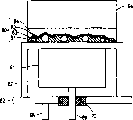
Figure 22 represents the topology example of the ultrasonic wave transmitting and receiving apparatus of the 8th example according to the present invention.
Ultrasonic wave transmitting and receiving apparatus involving vibrations device 61, be used to hold vibrator 61 can 62, be used to mate the acoustic impedance of vibrator 61 and the acoustic matching parts 64 of the acoustic impedance of the fluid that flows in can 62 outsides, and attachment 60 that are used to engage acoustic matching parts 64 and can 62.
Can 62 is preferably by having gratifying corrosion resistance and high-intensity material forms.Can 62 is for example formed by stainless steel.
Can 62 has the thickness of to 200 to 300 μ m.It is as follows that the thickness of can 62 is done thin reason: the first, when considering from vibrator 61 when acoustic matching parts 64 transmit sound, can ignore the acoustic impedance of can 62.The second, when transmitting by can 62, can reduce sound the decay of acoustic energy.But, when the thickness of can 62 is too small, will reduce stainless intensity as can 62 materials.The thickness of can 62 is as far as possible little, but will be enough to keep stainless satisfied intensity.
Can 62 holds vibrator 61 under the 7th the described sealing state of example.Thereby, prevent that gas or water are penetrated in the vibrator 61, therefore can prevent the deterioration or the fault of vibrator 61.
In the 8th example, propagate the sound of 500kHz.Therefore, wavelength of sound is 2 to 2.6 millimeters, and 1/4 of wavelength of sound is 0.5 to 0.65 millimeter.
The second layer 66 is formed by titanium oxide.The second layer 66 forms along the male and fomale(M﹠F) of ground floor 65.The second layer 66 has several microns thickness.
The 3rd layer of 67 glass that is lower than acoustic matching parts 64 material therefors by fusing point forms.The 3rd layer 67 one side engages with the second layer 66, and the 3rd layer 67 another side engages with acoustic matching parts 64.The 3rd layer of 67 thickness with 50 to 100 μ m.
After this, will the operation and the function of ultrasonic wave transmitting and receiving apparatus shown in Figure 22 be described.
When electrode 68 and 69 was applied the alternating voltage of 500kHz, vibrator 61 vibrated with about 500kHz.
The vibration of vibrator 61 propagates into acoustic matching parts 64 through can 62 and attachment 60 (ground floor 65, the second layer 66 and the 3rd layer 67).
Can 62 has the thickness of 200 to 300 μ m, and attachment 60 have the thickness of about 100 μ m.The thickness of the thickness of can 62 and attachment 60 is than the wavelength of sound much shorter that will propagate.Therefore, can ignore the influence of the acoustic impedance of can 62 and attachment 60.As a result, vibrator 61 can considered to be in the state adjacent with acoustic matching parts 64 that be similar to.
By the thickness of attenuating can 62 and the thickness of attachment 60, can reduce the decay of acoustic energy.
The vibration of vibrator 61 propagates in the air through acoustic matching parts 64.Vibrator 61 has about 30 * 10
6Kg/m
2The acoustic impedance of s, acoustic matching parts 64 have about 0.6 * 10
6m
2The acoustic impedance of s.Air has about 428kg/m
2The acoustic impedance of s.Therefore, vibrator 61 is 0.16 to the transfer voice of air than approximately.
The ultrasonic wave transmitting and receiving apparatus can be sent to vibrator 61 through acoustic matching parts 64 with the vibration of air, and vibrator 61 converts vibration to the signal of telecommunication in this case, and the signal of telecommunication is outputed to electrode 68 and 69.
Therefore, the ultrasonic wave transmitting and receiving apparatus converts the electrical signal to the mechanical oscillation of vibrator 61, and this vibration is sent in the air etc., or converts the vibration of air to the signal of telecommunication by vibrator 61, and receives these signals of telecommunication by electrode 68 and 69.
After this, will the function of ultrasonic wave transmitting and receiving apparatus shown in Figure 22 when the variation of ambient temperature be described.When the ambient temperature of ultrasonic wave transmitting and receiving apparatus changed, the assembly of ultrasonic wave transmitting and receiving apparatus shown in Figure 22 had the shape that comprises thickness, and this shape changes according to the coefficient of thermal expansion of assembly material.But, be 14.7 * 10 for stainless steel at 20 ℃ coefficient of thermal expansions
-6k
-1, be 15 to 16 * 10 for silver solder
-6k
-1, be 8.6 * 10 for titanium
-6k
-1And be 0.55 to 8 * 10 for glass
-6k
-1More much smaller by the assembly that these materials form than the change of shape of the assembly that forms by resin material.When particularly acoustic matching parts 64 were formed by glass, shape was very little with the amplitude of temperature change.Because the thickness of acoustic matching parts 64 can remain on 1/4 of wavelength of sound, output characteristic can be constrained to very little with variation of temperature.The fusing point of every kind of material is 400 ℃ or higher, unless therefore be placed under the very high temperature, assembly can not soften.So just guaranteed the stabilised quality of ultrasonic wave transmitting and receiving apparatus.
Stainless coefficient of thermal expansion obviously is different from the coefficient of thermal expansion of glass.Therefore, the direct joint of can 62 that is formed by stainless steel and the acoustic matching parts 64 that formed by glass causes too high pressure.Special when can 62 when 200 to 300 μ m approach, the composition surface will be bent or damage acoustic matching parts 64.
According to the present invention, in order to prevent this inconvenience, between glass component and parts of stainless steel, provide the second layer 66 that forms by the titanium material, it has the intermediate heat expansion rate between stainless steel and glass.Thereby reduced to be applied to the stress on the composition surface.In addition, the composition surface between the ground floor 65 and the second layer 66 forms male and fomale(M﹠F), so that the pressure direction that is applied on the composition surface changes.Thereby reduce the stress be applied on the second layer 66 and the 3rd layer 67.
The coefficient of thermal expansion of stainless coefficient of thermal expansion and ground floor 65 (silver solder) is roughly the same.Therefore, parts of stainless steel and ground floor 65 (silver solder) are inclined to contraction phase degree together in the horizontal direction.At this moment, the border between the second layer 66 (titanium) and ground floor 65 (silver solder) produces stress, and the coefficient of thermal expansion of the second layer 66 (titanium) is lower than the coefficient of thermal expansion of parts of stainless steel and ground floor 65.Simultaneously, the border between the 3rd layer 67 (low-melting glass) and the second layer 66 (titanium) produces stress, and the coefficient of thermal expansion of the 3rd layer 67 (low-melting glasses) is lower than the coefficient of thermal expansion of the second layer 66 (titanium).
The stress direction that is produced on the border between the 3rd layer 67 (low-melting glass) and the second layer 66 (titanium) is shown in the thick arrow among Figure 22.Stress vector can be divided into the force vector of above-below direction and the force vector of left and right directions, shown in the thin arrow among Figure 22.The vector of above-below direction is cancelled out each other, and the vector of left and right directions is cancelled out each other.As a result, reduced whole stress.
As mentioned above, can 62 harmony matching blocks 64 are bonded together by attachment 60, with the difference between the coefficient of thermal expansion of the coefficient of thermal expansion that lowers can 62 and acoustic matching parts 64.Because this structure has prevented the composition surface deflection, and prevent that acoustic matching parts 64 break away from can 62.Therefore, can provide the ultrasonic wave transmitting and receiving apparatus of characteristic with the temperature little change.
In example shown in Figure 22, ground floor 65 is formed by silver solder, and the second layer 66 is formed by titanium, and the 3rd layer 67 is formed by glass.Attachment 60 have the anti-structure that comprises the corrosion of gases such as sulphur.Because this structure can provide the transmitting and receiving apparatus of the ultrasonic wave with longer life.
Figure 23 represents another topology example of the ultrasonic wave transmitting and receiving apparatus of the 8th example according to the present invention.Ultrasonic wave transmitting and receiving apparatus shown in Figure 23 has such structure, promptly is used for comparing with ultrasonic wave transmitting and receiving apparatus shown in Figure 22, reduces the stress that is applied on the attachment 60 more.
These attachment 60 are included in the ground floor 71 that forms on the can 62, the second layer 72 that forms on ground floor, the 3rd layer 73 of forming on the second layer 72.
The second layer 72 forms on ground floor 71 off and on.In other words, the second layer 72 is divided into a plurality of partial layers.In example shown in Figure 23, the second layer 72 is divided into partial layer 72a, 72b and 72c.Partial layer 72a forms along the male and fomale(M﹠F) of partial layer 71a.Partial layer 72b forms along the male and fomale(M﹠F) of partial layer 71b.Partial layer 72c forms along the male and fomale(M﹠F) of partial layer 71c.
By forming the ground floor 71 and the second layer 72 as mentioned above off and on, even when coefficient of thermal expansion is very big, the variation of shape also can be restricted to very little.Therefore, can reduce the stress that is applied on the second layer 72 and the 3rd layer 73.In addition, intermittently the variation of the partial layer shape that exists can be cancelled out each other, and therefore can reduce the stress that is applied on the second layer 72 and the 3rd layer of 73 composition surface.
In example shown in Figure 23, form the ground floor 71 and the second layer 72 off and on.Therefore, the 3rd layer 73 and can 62 are in contact with one another in the part of can 62.But the contact area between the 3rd layer 73 and the can 62 is very little, though therefore the 3rd layer 73 with the significantly different situation of can 62 coefficient of thermal expansions under, the 3rd layer 73 and can 62 also can be bonded together.Even when the 3rd layer 73 and can 62 can't be bonded together, also can ignore the influence that contact condition is not propagated vibration (sound), because contact area is very little.
The operation of ultrasonic wave transmitting and receiving apparatus shown in Figure 23 and function class are similar to the operation and the function of ultrasonic wave transmitting and receiving apparatus shown in Figure 22, have no longer described here.
By forming ground floor 71 off and on, can reduce the stress that is applied on the attachment 60.This allows acoustic matching parts 64 to be formed by the coefficient of thermal expansion material littler than glass.As a result, can provide the ultrasonic wave transmitting and receiving apparatus of output characteristic with the temperature little change.
Figure 24 represents another topology example of the ultrasonic wave transmitting and receiving apparatus of the 8th example according to the present invention.
These attachment 60 are included in the ground floor 81 that forms on the can 62, the second layer 82 that forms on ground floor, the 3rd layer 83 of forming on the second layer 82.
Use the alumina particle 82 of different sizes to have the advantage of the male and fomale(M﹠F) that helps formation ground floor 81.
Figure 25 represents another topology example of the ultrasonic wave transmitting and receiving apparatus of the 8th example according to the present invention.Ultrasonic wave transmitting and receiving apparatus shown in Figure 25 has such structure, promptly reduces the stress that is applied on the attachment 60 more than ultrasonic wave transmitting and receiving apparatus shown in Figure 24.
These attachment 60 are included on the can 62 ground floor 91 that forms, at the second layer 92 that forms on the ground floor and the 3rd layer 93 of forming on the second layer 92.
By forming the ground floor 91 and the second layer 92 as mentioned above off and on, even when coefficient of thermal expansion is very big, the variation of shape also can be restricted to very little.In addition, the change of shape of the partial layer that intermittently exists can be cancelled out each other.
Therefore, in ultrasonic wave transmitting and receiving apparatus shown in Figure 25, the first, can reduce the stress on the composition surface that is applied to the ground floor 91 and the second layer 92.The second, can reduce the stress on the composition surface that is applied to the second layer 92 and the 3rd layer 93.As a result, be applied to stress on the attachment shown in Figure 25 60 less than the stress that is applied on the attachment shown in Figure 24 60.
By forming ground floor 91 off and on, can reduce the stress that is applied on the attachment 60.This allows acoustic matching parts 64 to be formed by the material of coefficient of thermal expansion less than glass.As a result, can provide the ultrasonic wave transmitting and receiving apparatus of characteristic with the temperature little change.
(example 9)
Figure 26 represents to illustrate the process of the joint method of the 9th example according to the present invention.After process shown in Figure 26, the acoustic matching parts 64 and the can 62 of ultrasonic wave transmitting and receiving apparatus shown in Figure 22 are bonded together by attachment 60.
At step 101 (hybrid technique), the silver solder particle that is used to form ground floor 65 mixes with estimated rate with the titanium particle that is used to form the second layer 66, thereby forms mixture.
In order to make the distribution of material in the mixture even, preferably add by what the tackifying resin material formed and help curing agent.For example, can use fusing point to be starkly lower than the curing agent that helps of silver, copper or titanium.In this case, help curing agent preferably can before the silver solder fusing that is used to form ground floor 65, evaporate.
At step 102 (mixture application process), mixture is spread upon on the can 62.
At step 103 (mixture heating process), make the can that scribbles mixture be placed in the vacuum furnace and be heated.
At step 104 (low-melting glass application process), from vacuum furnace, remove can 62, and will be used to form the 3rd layer 67 low-melting glass and be applied on the second layer 66 with ground floor 65 and second layer 66.Help curing agent and low-melting glass by mixing, can smear low-melting glass equably by what resin material formed.
At step 105 (joint technology), acoustic matching parts 64 are placed on the low-melting glass, are heated to about 450 ℃ in atmosphere, and the load of about 30g is provided simultaneously.Low-melting glass melts, thereby engages with the titanium oxide film of the second layer 66, also with the glass bond of acoustic matching parts 64.Because the glass of acoustic matching parts 64 is softening under 600 ℃ or higher temperature, so the glass of acoustic matching parts 64 can not melt under 450 ℃.
The particle that mixes the multiple material with different heat expansion rate to be producing mixture, and melts this mixture.By this way, can form attachment with the different layer of a plurality of coefficient of thermal expansions.
In the 9th example, titanium is as the material of easy especially oxidation.Silver solder is as the material of proportion greater than titanium.Titanium has 4.54g/cm
3Density, yellow gold has 9 to 10g/cm
3Density.When these mixtures of material fusings, titanium floats on the silver solder, so titanium is oxidized.By this way, can on the silver soldering bed of material, form oxidation titanium film.
In the 9th example, in step 103 (Hybrid Heating technology), mixture is heated under about 800 to 900 ℃ temperature.This heating-up temperature fully is lower than the fusing point of titanium, and 1650 ℃, but be higher than the fusing point of silver solder.Therefore, titanium can be to float on the fluid of silver solder.Float over top titanium and the oxygen in the vacuum furnace and react, thereby melted, the result forms oxidation titanium film.By this way, form the second layer 66.
In the 9th example, the size of oxidized titanium particle is set to 150 μ m or littler easily.Therefore, titanium and oxygen react, and the fusing point that needn't be heated to titanium just melts.As a result, can form and be thinned to several microns oxidation titanium film.
In the 9th example, have 8.6 * 10 at 20 ℃ as the titanium of easy oxidized material
-6K
-1Coefficient of thermal expansion.Proportion has 15 to 17 * 10 greater than the silver solder of titanium at 20 ℃
-6K
-1Coefficient of thermal expansion.That is to say that the formation with titanium film of little coefficient of thermal expansion makes the second layer 66, ground floor 65 and can 62 have the coefficient of thermal expansion that increases progressively.Therefore, can reduce owing to be used to form the 3rd layer 67 low-melting glass coefficient of thermal expansion and be used to form the stress that the difference between the stainless coefficient of thermal expansion of can 62 produces.Therefore, even when acoustic matching parts 64 are formed by glass, acoustic matching parts 64 and can 62 also can be bonded together.
Figure 27 represents to engage according to process shown in Figure 26 the profile of the major part of the ultrasonic wave transmitting and receiving apparatus that acoustic matching parts 64 and can 62 make.
In Figure 27, Reference numeral 62 expression stainless steel metal boxes.The Reference numeral 111 expression silver soldering bed of materials (ground floor), Reference numeral 112 expression titanium oxide layers (second layer), Reference numeral 113 expression alumina particles, Reference numeral 114 expression low-melting glasses (the 3rd layer).Reference numeral is represented glass acoustic matching parts.
Here, by alumina particle 113 is spilt into the silver soldering bed of material 111, the silver soldering bed of material and titanium oxide layer 112 form male and fomale(M﹠F).
Can understand from Figure 27, can 62 is in the same place with the silver soldering bed of material 111 seamless combination.The silver soldering bed of material 111 also is in the same place by seamless combination with titanium oxide layer 112.
When the mixture that comprises silver solder particle and titanium particle melted, silver solder particle and titanium particle were bonded together under soft state.As a result, two-layer can be in the composition surface seamless combination.By utilizing alumina particle 113 to form male and fomale(M﹠F), can reduce the stress that is applied on titanium oxide layer 112 and the low melting point glass layer 114.
Alumina particle 113 has and is lower than 6 to 7 * 10 of silver solder
-6K
-1Coefficient of thermal expansion.When alumina particle 113 was included in the silver soldering bed of material 111, the silver soldering bed of material 111 parts had the low-thermal-expansion rate.Therefore, can reduce the coefficient of thermal expansion of the whole silver soldering bed of material 111.As a result, reduced the stress that is applied on the low melting point glass layer 114.
The male and fomale(M﹠F) on composition surface can make the stress direction that is applied on the composition surface change.Therefore, can reduce the stress that is applied on the low melting point glass layer 114.Because the glass of low-melting glass harmony matching block 64 has roughly the same coefficient of thermal expansion, so there is not stress to be applied on the composition surface between the low melting point glass layer 114 harmony matching blocks 64 in fact.
Because above-mentioned structure, the attachment 60 that acoustic matching parts 64 and being used to engage acoustic matching parts 64 and can 62 can be formed by the material with low-thermal-expansion rate.Therefore, can reduce the characteristic of ultrasonic wave transmitting and receiving apparatus with variation of temperature.
In the 9th example, particularly, titanium can react with nitrogen or carbon, to form titanium nitride film or titanium carbonitride film as the second layer 66.In this case, titanium nitride film or titanium carbonitride film have the effect identical with oxidation titanium film.Can form titanium nitride film by the mixture of heat packs titaniferous particle in nitrogen and silver solder particle.The composition of film can be set according to the material composition that engages with this film.
In above-mentioned example, gas is used as an example measuring main body.Perhaps, fluid also can be the main body of measuring.
Industrial applicibility
In acoustic matching parts according to the present invention, at least one in a plurality of small pieces is at contact site Divide with a plurality of small pieces in another engages at least, in the acoustic matching parts, to form the gap. Logical Cross in the contact portion engage tabs, the contact area between the small pieces increases. Therefore, can strengthen Coupling between the small pieces. This just provides the effect that reduces in the vibration attenuation of small pieces Coupling point. Therefore, the vibration of vibrator can be delivered to effectively as the fluid of measuring main body.
Have at small pieces in the situation of unbodied three-dimensional structure, can increase in the acoustic matching parts The gap that forms. Therefore, the density of acoustic matching parts can be lower than the intrinsic density of patch material. As a result, can reduce at an easy rate the acoustic impedance of acoustic matching parts. Therefore, the vibration of vibrator Can effectively be delivered to as the fluid of measuring main body.
Be placed to sound not by in the situation of acoustic matching parts linear propagation at small pieces, can fall The velocity of sound that allows of matching block in a low voice. As a result, can reduce the acoustic impedance of acoustic matching parts. Therefore, the vibration of vibrator can be delivered to effectively as the fluid of measuring main body.
In the situation that small pieces are formed by glass or ceramic material, can provide to have lower heat The acoustic matching parts of expansion rate and stable temperature characterisitic. Therefore, can realize having high accuracy The ultrasonic wave transmitting and receiving apparatus. Acoustic matching parts obtained above can be resisted by for example gas The corrosion that the impurity such as the sulphur that comprises in the body cause.
By the method for manufacturing acoustic matching parts according to the present invention, soft by small pieces are heated to Change the temperature of patch material and a plurality of small pieces are bonded together. By epoxy resin etc. form sticking Connecing agent need to be for the manufacture of the acoustic matching parts. The acoustic matching parts are because the weight of bonding agent can Lighten. Therefore, can reduce the acoustic impedance of acoustic matching parts. Therefore, the vibration of vibrator can Effectively to be delivered to as the fluid of measuring main body.
In ultrasonic wave transmitting and receiving apparatus according to the present invention, be used for engaging and hold vibrator The attachment of can harmony matching block have the can coefficient of thermal expansion of attenuating and acoustic matching The structure of difference between the parts coefficient of thermal expansion. Therefore, have the different heat expansion rate can and The acoustic matching parts can firmly engage, and needn't utilize based on the resin of for example epoxy resin Bonding agent.
Claims (24)
- One kind when sound when first object propagates into second object, be used to mate the acoustic matching parts of the acoustic impedance of the acoustic impedance of first object and second object, wherein:The acoustic matching parts comprise a plurality of small pieces with bossing and recessed portion, andIn a plurality of small pieces at least one in contact portion and a plurality of small pieces another engages at least, in the acoustic matching parts, to form the gap.
- 2. according to the acoustic matching parts of claim 1, each in wherein a plurality of small pieces all has unbodied three-dimensional structure.
- 3. according to the acoustic matching parts of claims 1, place a plurality of small pieces and pass through acoustic matching parts linear propagation to prevent sound.
- 4. according to the acoustic matching parts of claim 1, each in wherein a plurality of small pieces is made of glass or ceramic material.
- 5. method of making the acoustic matching parts, described acoustic matching parts are used at sound mating the acoustic impedance of first object and the acoustic impedance of second object when first object propagates into second object, and the method comprising the steps of:(a) form a plurality of small pieces with bossing and recessed portion; In in a plurality of small pieces at least one and a plurality of small pieces another engages at least, in the acoustic matching parts, to form the gap.
- 6. according to the method for the manufacturing acoustic matching parts of claim 5, on a plurality of small pieces, apply the step of load when wherein step (b) is included in a plurality of small pieces of heating.
- 7. according to the method for the manufacturing acoustic matching parts of claim 5, wherein step (a) comprises step:Mix a plurality of small pieces and fluid;WithEvaporative fluid from the mixture of a plurality of small pieces and fluid.
- 8. according to the method for the manufacturing acoustic matching parts of claim 7, wherein the proportion of fluid is less than the proportion of a plurality of small pieces.
- 9. the method for manufacturing acoustic matching parts is according to Claim 8 wherein evaporated this fluid after a plurality of small pieces are deposited in the fluid.
- 10. according to the method for the manufacturing acoustic matching parts of claim 5, wherein form a plurality of small pieces by a plurality of hollow ball of efflorescence.
- 11. according to the method for the manufacturing acoustic matching parts of claim 10, the density of wherein coming the guide sound matching block according to the efflorescence degree of a plurality of hollow ball.
- 12. according to the method for the manufacturing acoustic matching parts of claim 11, the ratio value representation of the volume of a plurality of small pieces of obtaining after by the volume before a plurality of hollow ball efflorescence and a plurality of hollow ball efflorescence of the efflorescence degree of a plurality of hollow ball wherein.
- 13. a ultrasonic wave transmitting and receiving apparatus comprises:Vibrator;Be used to hold the can of this vibrator;The acoustic matching parts of the acoustic impedance of the fluid that is used to mate the vibrator acoustic impedance and flows in the can outside; WithBe used to engage the attachment of acoustic matching parts and can,Wherein:The acoustic matching parts comprise a plurality of small pieces with bossing and recessed portion, and in a plurality of small pieces at least one in contact portion and a plurality of small pieces another engages at least, in the acoustic matching parts, forming the gap, andThese attachment have the structure that is used to reduce difference between the can coefficient of thermal expansion harmony matching block coefficient of thermal expansion.
- 14. 13 the ultrasonic wave transmitting and receiving apparatus according to the present invention, wherein attachment are included in the ground floor that forms on the can, the second layer that forms on ground floor, and the 3rd layer of forming on the second layer; Ground floor is made of silver solder; The second layer is made of titanium; With the 3rd layer constitute by silver solder.
- 15. according to the ultrasonic wave transmitting and receiving apparatus of claims 14, wherein these attachment further are included in the 3rd layer and go up the 4th layer of forming and the layer 5 that forms on the 4th layer, the 4th layer is ceramic wafer or glass plate; And layer 5 is made of the glass that fusing point is lower than the 4th layer material fusing point.
- 16. according to the ultrasonic wave transmitting and receiving apparatus of claims 13, wherein attachment are included in the ground floor that forms on the can, and form ground floor on the basis of the mixture that obtains by combined silver welding powder and titanium valve.
- 17. according to the ultrasonic wave transmitting and receiving apparatus of claims 13, wherein attachment are included in the ground floor that forms on the can, and by the combined silver welding powder, form ground floor on the basis of titanium valve and ceramic powders and the mixture that obtains.
- 18. according to the ultrasonic wave transmitting and receiving apparatus of claims 13, wherein attachment are included in ground floor that forms on the can and the second layer that forms on ground floor, and the composition surface between the ground floor and the second layer has concaveconvex shape.
- 19., wherein on can, form ground floor off and on according to the ultrasonic wave transmitting and receiving apparatus of claims 18.
- 20. according to the ultrasonic wave transmitting and receiving apparatus of claim 18, wherein ground floor comprises that a plurality of coefficient of thermal expansions are lower than the particle of ground floor material coefficient of thermal expansion rate.
- 21. according to the ultrasonic wave transmitting and receiving apparatus of claims 13, whereinThese attachment be included in the ground floor that forms on the can and the second layer that on ground floor, forms andThe mixture that comprises second particle of first particle of first material and second material by heating forms ground floor, that wherein said first material is easy to is oxidized, nitrogenize or carbonization, the proportion of described second material is greater than the proportion of first material, fusing point is lower than the fusing point of first material, and ground floor forms second material layer; Form on second material layer with the second layer, the second layer forms oxidation, nitrogenize or carbonization first material and the layer that obtains.
- 22. according to the ultrasonic wave transmitting and receiving apparatus of claim 21, wherein the first material coefficient of thermal expansion rate is lower than the second material coefficient of thermal expansion rate.
- 23. according to the ultrasonic wave transmitting and receiving apparatus of claim 21, wherein at the fusing point that is lower than first material be higher than under the temperature of second material melting point and add hot mixt.
- 24. according to the ultrasonic wave transmitting and receiving apparatus of claim 21, wherein first particle is of a size of 150 μ m or littler.
Applications Claiming Priority (18)
| Application Number | Priority Date | Filing Date | Title |
|---|---|---|---|
| JP322564/99 | 1999-11-12 | ||
| JP32256499A JP4277393B2 (en) | 1999-11-12 | 1999-11-12 | Ultrasonic generator |
| JP322564/1999 | 1999-11-12 | ||
| JP32633999A JP2001145194A (en) | 1999-11-17 | 1999-11-17 | Ultrasonic wave generator and method of manufacturing the same |
| JP326339/1999 | 1999-11-17 | ||
| JP326339/99 | 1999-11-17 | ||
| JP164276/00 | 2000-06-01 | ||
| JP2000164276A JP2001346295A (en) | 2000-06-01 | 2000-06-01 | Acoustic matching member and its manufacturing method |
| JP164276/2000 | 2000-06-01 | ||
| JP2000303342A JP2002112394A (en) | 2000-10-03 | 2000-10-03 | Junction of substances with different coefficients of thermal expansion and ultrasonic wave transmitter- receiver using it and its manufacturing method |
| JP303341/00 | 2000-10-03 | ||
| JP2000303341A JP2002112393A (en) | 2000-10-03 | 2000-10-03 | Junction of substances with different coefficients of thermal expansion and ultrasonic wave transmitter- receiver using it |
| JP303341/2000 | 2000-10-03 | ||
| JP303342/00 | 2000-10-03 | ||
| JP303342/2000 | 2000-10-03 | ||
| JP2000317451A JP4439710B2 (en) | 2000-10-18 | 2000-10-18 | Acoustic matching member and manufacturing method thereof |
| JP317451/00 | 2000-10-18 | ||
| JP317451/2000 | 2000-10-18 |
Publications (2)
| Publication Number | Publication Date |
|---|---|
| CN1342385A CN1342385A (en) | 2002-03-27 |
| CN1145407C true CN1145407C (en) | 2004-04-07 |
Family
ID=27554602
Family Applications (1)
| Application Number | Title | Priority Date | Filing Date |
|---|---|---|---|
| CNB008043922A Expired - Fee Related CN1145407C (en) | 1999-11-12 | 2000-11-10 | Acoustic matching material, method of manufacture thereof, and ultrasonic transmitter using acoustic matching material |
Country Status (7)
| Country | Link |
|---|---|
| US (1) | US6545947B1 (en) |
| EP (1) | EP1170978B1 (en) |
| KR (1) | KR100423381B1 (en) |
| CN (1) | CN1145407C (en) |
| AT (1) | ATE548860T1 (en) |
| AU (1) | AU1308601A (en) |
| WO (1) | WO2001037609A1 (en) |
Families Citing this family (9)
| Publication number | Priority date | Publication date | Assignee | Title |
|---|---|---|---|---|
| US6788620B2 (en) * | 2002-05-15 | 2004-09-07 | Matsushita Electric Ind Co Ltd | Acoustic matching member, ultrasound transducer, ultrasonic flowmeter and method for manufacturing the same |
| US7084552B2 (en) * | 2003-01-16 | 2006-08-01 | The Ultran Group, Inc. | Anisotropic acoustic impedance matching material |
| CN1839660B (en) * | 2003-08-22 | 2011-03-02 | 松下电器产业株式会社 | Sound matching body, process for producing the same, ultrasonic sensor and ultrasonic wave transmitting/receiving system |
| CN102985171B (en) | 2010-07-14 | 2016-03-02 | 日本碍子株式会社 | Ceramic filter |
| EP2733959A4 (en) * | 2011-07-13 | 2014-12-24 | Panasonic Corp | Method for manufacturing acoustic matching body, acoustic matching body, ultrasonic transducer using acoustic matching body, and ultrasonic flowmeter |
| US10442724B2 (en) | 2015-09-25 | 2019-10-15 | Hitachi Ltd. | Joining material and joined body using same |
| CN110400869A (en) * | 2019-06-19 | 2019-11-01 | 中国科学院声学研究所东海研究站 | A kind of medium and its acoustic impedance regulation method of controllable acoustic impedance |
| US11664779B2 (en) | 2019-07-03 | 2023-05-30 | Toyota Motor Engineering & Manufacturing North America, Inc. | Acoustic impedance matching with bubble resonators |
| JP7296581B2 (en) * | 2019-08-08 | 2023-06-23 | パナソニックIpマネジメント株式会社 | ultrasonic sensor |
Family Cites Families (10)
| Publication number | Priority date | Publication date | Assignee | Title |
|---|---|---|---|---|
| US4211948A (en) * | 1978-11-08 | 1980-07-08 | General Electric Company | Front surface matched piezoelectric ultrasonic transducer array with wide field of view |
| US4297607A (en) * | 1980-04-25 | 1981-10-27 | Panametrics, Inc. | Sealed, matched piezoelectric transducer |
| GB2225426B (en) * | 1988-09-29 | 1993-05-26 | Michael John Gill | A transducer |
| JP3039971B2 (en) * | 1989-09-19 | 2000-05-08 | 株式会社日立製作所 | Bonded piezoelectric device, manufacturing method, and bonded piezoelectric element |
| JP2920776B2 (en) | 1990-04-13 | 1999-07-19 | 東芝セラミックス株式会社 | Ultrasonic probe |
| GB2246349B (en) * | 1990-07-24 | 1994-06-22 | British Gas Plc | Method for bonding together hollow glass spheres |
| US5553035A (en) * | 1993-06-15 | 1996-09-03 | Hewlett-Packard Company | Method of forming integral transducer and impedance matching layers |
| JP3295547B2 (en) | 1994-08-19 | 2002-06-24 | 株式会社リコー | G3 protocol measurement device |
| JP3580879B2 (en) * | 1995-01-19 | 2004-10-27 | 浜松ホトニクス株式会社 | Electron tube device |
| DE59510158D1 (en) * | 1995-09-28 | 2002-05-16 | Endress Hauser Gmbh Co | ultrasound transducer |
-
2000
- 2000-11-10 AU AU13086/01A patent/AU1308601A/en not_active Abandoned
- 2000-11-10 CN CNB008043922A patent/CN1145407C/en not_active Expired - Fee Related
- 2000-11-10 AT AT00974950T patent/ATE548860T1/en active
- 2000-11-10 US US09/889,077 patent/US6545947B1/en not_active Expired - Fee Related
- 2000-11-10 WO PCT/JP2000/007981 patent/WO2001037609A1/en active IP Right Grant
- 2000-11-10 KR KR10-2001-7008850A patent/KR100423381B1/en not_active IP Right Cessation
- 2000-11-10 EP EP00974950A patent/EP1170978B1/en not_active Expired - Lifetime
Also Published As
| Publication number | Publication date |
|---|---|
| WO2001037609A1 (en) | 2001-05-25 |
| EP1170978A4 (en) | 2009-03-18 |
| AU1308601A (en) | 2001-05-30 |
| KR20020007291A (en) | 2002-01-26 |
| KR100423381B1 (en) | 2004-03-18 |
| EP1170978A1 (en) | 2002-01-09 |
| CN1342385A (en) | 2002-03-27 |
| ATE548860T1 (en) | 2012-03-15 |
| US6545947B1 (en) | 2003-04-08 |
| EP1170978B1 (en) | 2012-03-07 |
Similar Documents
| Publication | Publication Date | Title |
|---|---|---|
| CN1193253C (en) | Platform and optical module, and producing method and optical transmission device | |
| CN1046805C (en) | Optical fiber array | |
| CN1090887C (en) | Ultrasonic transmitter-receiver | |
| CN1249405C (en) | Acoustic matching layer, ultrasonic transmitter-receiver and ultrasonic flowmeter | |
| CN1145407C (en) | Acoustic matching material, method of manufacture thereof, and ultrasonic transmitter using acoustic matching material | |
| CN1143407C (en) | High frequency filter | |
| CN1201383C (en) | Electronic parts mounting method and device therefor | |
| CN1200793C (en) | Method for machining work by laser beam | |
| CN1163058C (en) | Camera device | |
| CN1740814A (en) | Ultrasonic sensor | |
| CN1967853A (en) | Semiconductor device and manufacturing method of the same | |
| CN1224137C (en) | Electric resistance measuring connector and measuring device and measuring method for circuit board electric resistance | |
| CN1649920A (en) | Film adhesives containing maleimide and related compounds and methods for use thereof | |
| CN1703929A (en) | Ultrasonic sensor | |
| CN1788415A (en) | Acoustic boundary wave device | |
| CN86104074A (en) | Can be blended in the very thermoplastic compounds of high content of pulverulent mineral materials that contains in the polymkeric substance | |
| CN1170284A (en) | Optical module including photoreception device | |
| CN1573363A (en) | Optical part and its manufacturing method | |
| CN1397024A (en) | Heater module and optical waveguide module | |
| CN1750256A (en) | Optical semiconductor device, method for fabricating the same, lead frame and electronic equipment | |
| CN1942022A (en) | Capacitor microphone, diaphragm and manufacturing method thereof | |
| CN1558920A (en) | Epoxy resin compositions and semiconductor devices | |
| CN1222026C (en) | Device and method for forming bump | |
| CN1774655A (en) | Optical fiber, optical fiber connecting method, and optical connector | |
| CN1314246A (en) | Ink jet head and its producing method |
Legal Events
| Date | Code | Title | Description |
|---|---|---|---|
| C10 | Entry into substantive examination | ||
| SE01 | Entry into force of request for substantive examination | ||
| C06 | Publication | ||
| PB01 | Publication | ||
| C14 | Grant of patent or utility model | ||
| GR01 | Patent grant | ||
| C17 | Cessation of patent right | ||
| CF01 | Termination of patent right due to non-payment of annual fee |
Granted publication date: 20040407 Termination date: 20111110 |