Detailed Description
Exemplary embodiments of the present disclosure are described below with reference to the accompanying drawings, in which various details of the embodiments of the disclosure are included to assist understanding, and which are to be considered as merely exemplary. Accordingly, those of ordinary skill in the art will recognize that various changes and modifications of the embodiments described herein can be made without departing from the scope and spirit of the present disclosure. Also, descriptions of well-known functions and constructions are omitted in the following description for clarity and conciseness.
The technical scheme of the embodiment of the disclosure is applied to the technical fields of automatic driving, high-precision maps, map navigation, intelligent transportation and the like, and is particularly applied to the quality control scene of field data acquired by the high-precision maps, the link between field acquisition and interior production, and the precision quality control is carried out on a plurality of tracks acquired by the field based on elevation difference. The technical scheme can be applied to quality control equipment for collecting tracks of high-precision maps, the collected tracks can be displayed on an interface of the quality control equipment, identified abnormal tracks can be identified on the interface, and the quality control equipment can be conveniently checked and monitored by quality control personnel in a static or dynamic display mode and the like. The whole quality control process is automatically realized, the abnormal track can be rapidly identified, and the risk of precision abnormality is reduced. In addition, the quality control result can be identified again in a manual quality control mode, so that the precision of the field data is further improved. The track after quality control is output to the interior production link, and the abnormal track can be prevented from flowing into the interior production link of the high-precision map, so that the waste of production capacity is effectively avoided, the reliability of the high-precision map is improved, and the automatic driving protection and navigation is realized.
In the embodiment of the disclosure, during field collection of the high-precision map, the collection device can automatically acquire and record the position information of the track along the driving direction, including x, y and z values. The two-dimensional map used in the quality control process can be a standard two-dimensional road network (also called as a base map), and the two-dimensional road network is matched in the acquisition track range based on two dimensions of elevation and plane distance, so that an abnormal track is identified, the track with the elevation or the plane precision not meeting the quality requirement is ensured not to flow into the production link of the high-precision map, and the quality abnormity of high-precision map product data caused by unqualified field data is avoided.
The elevation difference referred to in the embodiments of the present disclosure refers to the distance between two points in the Z direction, and may be calculated using the absolute value of the difference between the Z coordinate values of the two points, that is, Δ H ═ Z1-Z2 |; alternatively, formulas may be used
The calculation is not limited specifically; wherein, Z1 and Z2 are Z coordinate values of two points respectively, and Δ H is the height difference of the two points.
In the embodiments of the present disclosure, it is,the planar distance between two points is considered to be the distance between two points in a plane after ignoring the distance in the Z direction, i.e., the height. However, in the actual scene, the two points may have different coordinates in the Z direction, i.e., located on planes at different heights. The plane distance can be calculated using the following formula:
wherein, X1 and Y1 are X coordinate values and Y coordinate values of one point, X2 and Y2 are X coordinate values and Y coordinate values of another point, and Δ L is a planar distance between the two points, which will not be described again below.
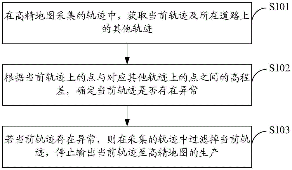
Fig. 1 is a schematic diagram of a quality control method for high-precision map track acquisition in an embodiment of the present disclosure. As shown in fig. 1, the method includes:
s101: acquiring a current track and other tracks on a road in the tracks acquired by the high-precision map;
s102: determining whether the current track is abnormal or not according to the elevation difference between the point on the current track and the point on the corresponding other track;
s103: and if the current track is abnormal, filtering the current track from the acquired tracks, and stopping outputting the current track to the production of the high-precision map.
In one embodiment, S102 may include:
under the condition that other tracks are multiple tracks, positioning a reference line on a two-dimensional map corresponding to a road, and determining the intersection points of the reference line, the current track and the multiple tracks;
and determining whether the current track is abnormal or not according to the obtained elevation difference between the intersection points and a preset first threshold value.
The method for determining the abnormal track based on the elevation difference between the current track and the other tracks has the advantages that the calculation is convenient, the realization is easy, whether the current track is abnormal or not can be determined by comparing the threshold values, and an effective quality control means is provided for the track acquired by the high-precision map.
In one embodiment, determining whether there is an abnormality in the current trajectory according to the obtained elevation difference between the intersection points and a preset first threshold includes:
if the plurality of tracks are two tracks in the same direction as the current track, the intersection point of the current track and the reference line is a first intersection point, and the intersection points of the two tracks and the reference line are a second intersection point and a third intersection point, calculating the elevation difference of any two points of the first intersection point, the second intersection point and the third intersection point;
and if the elevation difference between the first intersection point and the second intersection point and the elevation difference between the first intersection point and the third intersection point both exceed a preset first threshold value, and the elevation difference between the second intersection point and the third intersection point does not exceed the first threshold value, determining that the current track is abnormal.
According to the method for detecting whether the current track is abnormal or not, the abnormal current track can be effectively identified based on the elevation difference by means of the two tracks acquired in the same direction, and the condition shows that the elevation difference between the current track and other tracks in the same direction is obviously overlarge, the abnormal track belongs to the abnormal track in the scene of the same road, the abnormal track is filtered, the abnormal track is stopped being output to the production of a high-precision map, the risk of precision abnormality is reduced, and the precision of field data and the reliability of the high-precision map are improved.
In one embodiment, determining whether there is an abnormality in the current trajectory according to the obtained elevation difference between the intersection points and a preset first threshold includes:
if the plurality of tracks are two tracks opposite to the current track, the intersection point of the current track and the reference line is a fourth intersection point, and the intersection points of the two tracks and the reference line are a fifth intersection point and a sixth intersection point, calculating the elevation difference between the fourth intersection point and the fifth intersection point and the elevation difference between the fourth intersection point and the sixth intersection point;
and if the elevation difference between the fourth intersection point and the fifth intersection point or the elevation difference between the fourth intersection point and the sixth intersection point exceeds a preset first threshold, determining that the current track is abnormal.
According to the method for detecting whether the current track is abnormal or not, the abnormal current track can be effectively identified based on the elevation difference by means of the two tracks acquired in opposite directions, and the condition shows that the elevation difference between the current track and other opposite tracks is obviously overlarge, the abnormal track belongs to the abnormal track in the scene of the same road, the abnormal track is filtered, the abnormal track is stopped being output to the production of high-precision maps, the risk of abnormal precision is reduced, and the precision of field data and the reliability of high-precision maps are improved.
In one embodiment, the method may further include:
positioning a reference point on the current track, and taking the reference point as the circle center and the designated length as the radius to obtain a circular area;
determining a central line of a road on a two-dimensional map corresponding to the road;
and if the center line does not intersect with the circular area, determining that the current track has drift abnormality.
The mode for detecting whether the current track is abnormal is judged based on the current track and the road center line, the current track which generates drift can be effectively identified, the track is obviously out of the road range and belongs to an abnormal track, the output of the abnormal track to the production of high-precision maps is stopped, the risk of precision abnormality is reduced, and the precision of field data and the reliability of high-precision maps are improved.
In one embodiment, the method may further include:
and if the other tracks are opposite tracks, determining whether the current track has an abnormity crossed with the opposite tracks according to the plane distance between the point on the current track and the point on the corresponding opposite track.
The method can effectively identify the current track crossed with the opposite track based on the plane distance of the corresponding point of the current track and the opposite track, and the track running oppositely under the scene of the same road cannot be crossed, so that the current track crossed with the opposite track obviously belongs to an abnormal track, the output of the abnormal track to the production of high-precision maps is stopped, the risk of precision abnormality is reduced, and the precision of field data and the reliability of high-precision maps are improved.
In one embodiment, determining whether the current trajectory has an anomaly crossing the subtended trajectory according to a planar distance between a point on the current trajectory and a point on the corresponding subtended trajectory includes:
positioning a reference line on a two-dimensional map corresponding to the road to obtain a seventh intersection point of the reference line and the current track and an eighth intersection point of the reference line and the opposite track;
calculating the plane distance between the seventh intersection point and the eighth intersection point;
and if the plane distance is smaller than a preset second threshold value, determining that the current track has abnormity crossed with the opposite track.
The method can effectively identify the current track crossed with the opposite track based on the plane distance between the current track and the corresponding point of the opposite track, the track obviously belongs to an abnormal track, the output of the abnormal track to the production of high-precision maps is stopped, the risk of precision abnormality is reduced, and the precision of field data and the reliability of high-precision maps are improved.
In one embodiment, the method may further include:
determining two points on the current track according to the specified duration or the specified length, calculating the elevation difference of the two points, and determining that the current track has an elevation anomaly if the elevation difference of the two points exceeds a preset third threshold.
The method is suitable for the recognition scene of a single track, other tracks are not needed, whether the current track is abnormal in elevation or not can be determined based on the elevation difference of two points on the current track, the risk of accuracy abnormity is reduced, and the accuracy of field data and the reliability of a high-accuracy map are improved.
According to the method provided by the embodiment of the disclosure, the precision of the track acquired by the high-precision map can be controlled based on the elevation difference, an effective control means is provided, the abnormal track can be identified quickly, the risk of precision abnormality is reduced, the precision of field data is improved, the abnormal track is prevented from flowing into the production link of the high-precision map in the industry, the waste of production capacity is effectively avoided, the reliability of the high-precision map is improved, and the automatic driving protection navigation is realized.
Fig. 2a is a schematic diagram of a quality control method for high-precision map track acquisition in an embodiment of the present disclosure. As shown in fig. 2a, the method comprises:
s201: acquiring a current track and other tracks on a road in the tracks acquired by the high-precision map;
the tracks acquired by the high-precision map are usually multiple tracks, and may be multiple tracks acquired at one time, multiple tracks acquired at multiple times, and are not limited specifically. The current trajectory is located in the same road as the other trajectories, and the other trajectories may be the same direction as the current trajectory or opposite directions to the current trajectory.
S202: under the condition that other tracks are a plurality of tracks, positioning a reference line on a two-dimensional map corresponding to the road, and determining the intersection points of the reference line, the current track and the plurality of tracks;
the two-dimensional map is a map in which road information is reflected by horizontal and vertical coordinates in a plane. After the high-precision map acquires the current track, the road where the current track is located can be found in the two-dimensional map. The reference line may be a horizontal line perpendicular to the current road, or the like.
S203: determining whether the current track is abnormal or not according to the obtained elevation difference between the intersection points and a preset first threshold;
and the obtained intersection points comprise the intersection point of the reference line and the current track and the intersection point of the reference line and each other track. The size of the first threshold may be set according to needs, such as 2 meters or 2.5 meters, and the specific value is not limited.
S204: positioning a reference point on the current track, obtaining a circular area by taking the reference point as a circle center and the designated length as a radius, determining a center line of the road on a two-dimensional map corresponding to the road, and determining whether the current track has drift abnormality according to the center line and the circular area;
for example, the reference point may be determined on the current track according to a specified duration or a specified length, such as positioning one reference point every 1s or 2s, or positioning one reference point every 100 meters or 200 meters, and so on. The size of the radius may also be set according to needs, and may be set with reference to the road width of the road, for example, the size is set to be half of the road width, which is not specifically limited by the present disclosure. In addition, the center line may also be set according to the road width, for example, the center line is set to be half of the road width and a certain error range is allowed, and the disclosure does not specifically limit this.
In an embodiment, the determining whether there is an abnormality of drift in the current trajectory according to the central line and the circular area in S204 may specifically include:
and judging whether the center line and the circular area have intersection, if not, determining that the current track has drift abnormity, and if so, determining that the current track is normal.
Further, the above S204 may be replaced by the following steps:
positioning a plurality of reference points on the current track, obtaining a corresponding circular area by taking each reference point as a circle center and an appointed length as a radius, determining a center line of the road on a two-dimensional map corresponding to the road, sequentially matching whether the center line and each circular area have intersection, and determining that the current track has drift abnormality if the number of matching results without intersection reaches an appointed number.
Illustratively, the intersection of the centerline with the circular region includes at least one point on the centerline falling within the circular region, including on the boundary line of the circular region.
Fig. 2b is a schematic diagram of track drift in an embodiment of the disclosure. Referring to fig. 2b, in the current road of the two-dimensional map, the solid black line is the center line, which is generally half of the road width, and the fine adjustment can be performed within the allowable error range according to the actual situation. The dotted line with the arrow is the current track acquired by the high-precision map, the point A is one of the reference points positioned on the current track every 1s or every 20 m, and the circle area in the map is obtained by taking the point A as the center of a circle and taking the half of the road width as the radius. As is obvious from the figure, the central line is far away from the circular area, and the central line and the circular area do not have intersection, so that the current track can be determined to drift, and the current track is deviated to the outside of the road surface range and belongs to an abnormal track. Or, if there is no circular area with intersection in 10 consecutive seconds or 200 consecutive meters, that is, the current trajectory does not match the two-dimensional map for 10 consecutive times, it is determined that the current trajectory drifts and the plane precision is abnormal.
S205: under the condition that other tracks are opposite tracks, determining whether the current track has abnormity crossed with the opposite tracks according to the plane distance between the point on the current track and the point on the corresponding opposite track;
s206: and under the condition that the current track is determined to be abnormal, filtering the current track from the acquired tracks, and stopping outputting the current track to the production of the high-precision map.
FIG. 3a is a schematic diagram illustrating an abnormal trajectory determined based on an elevation difference of co-directional trajectories according to an embodiment of the present disclosure. As shown in fig. 3a, in an embodiment, the step S203 may specifically include:
s301: if the plurality of tracks are two tracks in the same direction as the current track, the intersection point of the current track and the reference line is a first intersection point, and the intersection points of the two tracks and the reference line are a second intersection point and a third intersection point, calculating the elevation difference of any two points of the first intersection point, the second intersection point and the third intersection point;
s302: and if the elevation difference between the first intersection point and the second intersection point and the elevation difference between the first intersection point and the third intersection point both exceed a preset first threshold value, and the elevation difference between the second intersection point and the third intersection point does not exceed the first threshold value, determining that the current track is abnormal.
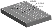
Fig. 3b is a schematic diagram of the equidirectional track height difference in an embodiment of the present disclosure. As shown in fig. 3b, two trajectories in the same direction on the current trajectory and the same road, that is, the trajectory 1 in the same direction and the trajectory 2 in the same direction in the figure, are obtained from the trajectories collected by the high-precision map. And positioning a reference line, namely a straight line perpendicular to the current road, on the two-dimensional map corresponding to the road. The intersection point of the reference line and the current track is A, the intersection point of the reference line and the equidirectional track 1 is B, and the intersection point of the reference line and the equidirectional track 2 is C. And respectively calculating the elevation difference of any two points of A, B and C, and if the elevation difference of A, B and A, C exceeds a specified threshold value by 2 meters, but the elevation difference of B and C does not exceed 2 meters, determining that the current track of A is abnormal in elevation and belongs to an abnormal track (namely the track is a few track), and the track of B, C is normal (namely the two tracks belong to a majority track). That is, most of the acquired tracks are normal tracks, and only a few tracks are abnormal tracks, that is, tracks with elevations obviously inconsistent with most of the other tracks are determined to be abnormal tracks, so that the principle that the minority is subject to the majority is met.
FIG. 4a is a schematic diagram illustrating an abnormal trajectory determined based on an elevation difference of opposite trajectories according to an embodiment of the present disclosure. As shown in fig. 4a, in an embodiment, the step S203 may specifically include:
s401: if the plurality of tracks are two tracks opposite to the current track, the intersection point of the current track and the reference line is a fourth intersection point, and the intersection points of the two tracks and the reference line are a fifth intersection point and a sixth intersection point, calculating the elevation difference between the fourth intersection point and the fifth intersection point and the elevation difference between the fourth intersection point and the sixth intersection point;
s402: and if the elevation difference between the fourth intersection point and the fifth intersection point or the elevation difference between the fourth intersection point and the sixth intersection point exceeds a preset first threshold, determining that the current track is abnormal.
Fig. 4b is a schematic diagram of the height difference of the opposite track in an embodiment of the disclosure. Referring to fig. 4b, two tracks, i.e., an opposite track 1 and an opposite track 2 in the figure, which are opposite to the current track and the same road are obtained from the tracks acquired by the high-precision map. And positioning a reference line, namely a straight line perpendicular to the current road, on the two-dimensional map corresponding to the road. The intersection of the reference line with the current trajectory is a, the intersection with the opposite trajectory 1 is B, and the intersection with the opposite trajectory 2 is C. And respectively calculating the height difference between A, B points and A, C points, and if the height difference between A, B points does not exceed a specified threshold value by 2 meters and the height difference between A, C points does not exceed 2 meters, determining that the current track elevation of the point A is not abnormal. If the difference between the heights of the A, B points exceeds 2 meters or the difference between the heights of the A, C points exceeds 2 meters, it can be determined that the current track where the point A is located is abnormal in elevation.
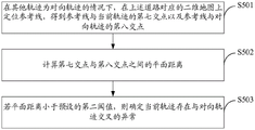
Fig. 5a is a schematic diagram of determining an abnormal trajectory based on a plane distance according to an embodiment of the present disclosure. As shown in fig. 5a, in an embodiment, the step S205 may specifically include:
s501: under the condition that other tracks are opposite tracks, positioning a reference line on a two-dimensional map corresponding to the road to obtain a seventh intersection point of the reference line and the current track and an eighth intersection point of the reference line and the opposite tracks;
s502: calculating the plane distance between the seventh intersection point and the eighth intersection point;
s503: and if the plane distance is smaller than a preset second threshold value, determining that the current track has abnormity crossed with the opposite track.
The second threshold may be set as needed, and the specific value is not limited.
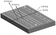
Fig. 5b is a schematic diagram of track crossing in an embodiment of the present disclosure. Referring to fig. 5b, the high-precision map collects the current track and the opposite track on the current road, and locates the reference line on the two-dimensional map corresponding to the road every 2s or 200 meters, wherein the intersection point M of the reference line and the current track and the intersection point N of the reference line and the opposite track are obtained by one-time location. And calculating the plane distance between M and N, and if the plane distance is less than a specified threshold value of 1 meter, determining that the current track intersects with the opposite track, and the precision is abnormal. Point a in the figure is schematically the intersection point where the two tracks cross.
Any of the above embodiments provided by the present disclosure may further include the following steps:
determining two points on the current track according to the specified duration or the specified length, calculating the elevation difference of the two points, and determining that the current track has an elevation anomaly if the elevation difference of the two points exceeds a preset third threshold.
FIG. 6 is a schematic diagram of single track elevation difference in an embodiment of the present disclosure. Referring to fig. 6, the current trajectory of the high-precision map acquisition is shown by the dotted line in the figure. And determining corresponding points on the current track every 1s or 100 meters, wherein two points A and B are obtained. And (8) calculating the elevation difference between the two points A, B, and if the elevation difference exceeds a specified threshold value by 20 meters, determining that an elevation anomaly exists in the current track.
According to the method provided by the embodiment of the disclosure, the precision of the track acquired by the high-precision map can be controlled based on the elevation difference, an effective control means is provided, the abnormal track can be identified quickly, the risk of precision abnormality is reduced, the precision of field data is improved, the abnormal track is prevented from flowing into the production link of the high-precision map in the industry, the waste of production capacity is effectively avoided, the reliability of the high-precision map is improved, and the automatic driving protection navigation is realized.
Fig. 7 is a block diagram of a quality control device for high-precision map trajectory acquisition in an embodiment of the present disclosure. As shown in fig. 7, the apparatus includes:
the acquisition module 701 is used for acquiring a current track and other tracks on a road in the high-precision map acquired track;
a determining module 702, configured to determine whether the current track is abnormal according to an elevation difference between a point on the current track and a point on the corresponding other track;
the control module 703 is configured to, if the current trajectory is abnormal, filter the current trajectory from the acquired trajectories, and stop outputting the current trajectory to the production of the high-precision map.
In one embodiment, the determining module 702 may include:
the intersection point determining unit is used for positioning a reference line on a two-dimensional map corresponding to a road under the condition that other tracks are a plurality of tracks, and determining intersection points of the reference line, the current track and the plurality of tracks;
and the abnormity determining unit is used for determining whether the current track is abnormal or not according to the obtained elevation difference between the intersection points and a preset first threshold value.
In one embodiment, the anomaly determination unit may be configured to:
if the plurality of tracks are two tracks in the same direction as the current track, the intersection point of the current track and the reference line is a first intersection point, and the intersection points of the two tracks and the reference line are a second intersection point and a third intersection point, calculating the elevation difference of any two points of the first intersection point, the second intersection point and the third intersection point;
and if the elevation difference between the first intersection point and the second intersection point and the elevation difference between the first intersection point and the third intersection point both exceed a preset first threshold value, and the elevation difference between the second intersection point and the third intersection point does not exceed the first threshold value, determining that the current track is abnormal.
In another embodiment, the anomaly determination unit may be configured to:
if the plurality of tracks are two tracks opposite to the current track, the intersection point of the current track and the reference line is a fourth intersection point, and the intersection points of the two tracks and the reference line are a fifth intersection point and a sixth intersection point, calculating the elevation difference between the fourth intersection point and the fifth intersection point and the elevation difference between the fourth intersection point and the sixth intersection point;
and if the elevation difference between the fourth intersection point and the fifth intersection point or the elevation difference between the fourth intersection point and the sixth intersection point exceeds a preset first threshold, determining that the current track is abnormal.
In one embodiment, the apparatus may further include:
the drift module is used for positioning a reference point on the current track and obtaining a circular area by taking the reference point as the circle center and the designated length as the radius; determining a central line of a road on a two-dimensional map corresponding to the road; and if the center line does not intersect with the circular area, determining that the current track has drift abnormality.
In one embodiment, the apparatus may further include:
and the crossing module is used for determining whether the current track has abnormity crossing with the opposite track according to the plane distance between the point on the current track and the point on the corresponding opposite track under the condition that other tracks are opposite tracks.
In one embodiment, the crossover module may be configured to:
under the condition that other tracks are opposite tracks, positioning a reference line on a two-dimensional map corresponding to a road to obtain a seventh intersection point of the reference line and the current track and an eighth intersection point of the reference line and the opposite tracks;
calculating the plane distance between the seventh intersection point and the eighth intersection point;
and if the plane distance is smaller than a preset second threshold value, determining that the current track has abnormity crossed with the opposite track.
In one embodiment, the determining module 702 may be further configured to:
determining two points on the current track according to the specified duration or the specified length, calculating the elevation difference of the two points, and determining that the current track has elevation abnormality if the elevation difference of the two points exceeds a preset third threshold.
The device provided by the embodiment of the disclosure can perform quality control on the track acquired by the high-precision map based on the elevation difference, provides an effective control means, can quickly identify the abnormal track, reduces the risk of accuracy abnormality, improves the accuracy of field data, avoids flowing the abnormal track into the production link of the high-precision map in the industry, effectively avoids the waste of production capacity, improves the reliability of the high-precision map, and protects the driving for automatic driving.
In the technical scheme of the disclosure, the acquisition, storage, application and the like of the personal information of the related user all accord with the regulations of related laws and regulations, and do not violate the good customs of the public order.
The present disclosure also provides an electronic device, a readable storage medium, and a computer program product according to embodiments of the present disclosure.
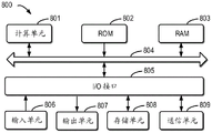
FIG. 8 illustrates a schematic block diagram of an example electronic device 800 that can be used to implement embodiments of the present disclosure. Electronic devices are intended to represent various forms of digital computers, such as laptops, desktops, workstations, personal digital assistants, servers, blade servers, mainframes, and other appropriate computers. The electronic device may also represent various forms of mobile devices, such as personal digital processing, cellular phones, smart phones, wearable devices, and other similar computing devices. The components shown herein, their connections and relationships, and their functions, are meant to be examples only, and are not meant to limit implementations of the disclosure described and/or claimed herein.
As shown in fig. 8, the apparatus 800 includes a computing unit 801 that can perform various appropriate actions and processes according to a computer program stored in a Read Only Memory (ROM)802 or a computer program loaded from a storage unit 808 into a Random Access Memory (RAM) 803. In the RAM 803, various programs and data required for the operation of the device 800 can also be stored. The calculation unit 801, the ROM 802, and the RAM 803 are connected to each other by a bus 804. An input/output (I/O) interface 805 is also connected to bus 804.
A number of components in the device 800 are connected to the I/O interface 805, including: an input unit 806, such as a keyboard, a mouse, or the like; an output unit 807 such as various types of displays, speakers, and the like; a storage unit 808, such as a magnetic disk, optical disk, or the like; and a communication unit 809 such as a network card, modem, wireless communication transceiver, etc. The communication unit 809 allows the device 800 to exchange information/data with other devices via a computer network such as the internet and/or various telecommunication networks.
Computing unit 801 may be a variety of general and/or special purpose processing components with processing and computing capabilities. Some examples of the computing unit 801 include, but are not limited to, a Central Processing Unit (CPU), a Graphics Processing Unit (GPU), various dedicated Artificial Intelligence (AI) computing chips, various computing units running machine learning model algorithms, a Digital Signal Processor (DSP), and any suitable processor, controller, microcontroller, and so forth. The calculation unit 801 executes the respective methods and processes described above, such as a quality control method of high-precision map trajectory acquisition. For example, in some embodiments, the quality control method of high-precision map trajectory acquisition may be implemented as a computer software program tangibly embodied in a machine-readable medium, such as storage unit 808. In some embodiments, part or all of the computer program can be loaded and/or installed onto device 800 via ROM 802 and/or communications unit 809. When loaded into RAM 803 and executed by the computing unit 801, a computer program may perform one or more steps of the quality control method of high precision map trajectory acquisition described above. Alternatively, in other embodiments, the computing unit 801 may be configured by any other suitable means (e.g., by means of firmware) to perform a quality control method of high precision map trajectory acquisition.
Various implementations of the systems and techniques described here above may be implemented in digital electronic circuitry, integrated circuitry, Field Programmable Gate Arrays (FPGAs), Application Specific Integrated Circuits (ASICs), Application Specific Standard Products (ASSPs), system on a chip (SOCs), Complex Programmable Logic Devices (CPLDs), computer hardware, firmware, software, and/or combinations thereof. These various embodiments may include: implemented in one or more computer programs that are executable and/or interpretable on a programmable system including at least one programmable processor, which may be special or general purpose, receiving data and instructions from, and transmitting data and instructions to, a storage system, at least one input device, and at least one output device.
Program code for implementing the methods of the present disclosure may be written in any combination of one or more programming languages. These program codes may be provided to a processor or controller of a general purpose computer, special purpose computer, or other programmable data processing apparatus, such that the program codes, when executed by the processor or controller, cause the functions/operations specified in the flowchart and/or block diagram to be performed. The program code may execute entirely on the machine, partly on the machine, as a stand-alone software package partly on the machine and partly on a remote machine or entirely on the remote machine or server.
In the context of this disclosure, a machine-readable medium may be a tangible medium that can contain, or store a program for use by or in connection with an instruction execution system, apparatus, or device. The machine-readable medium may be a machine-readable signal medium or a machine-readable storage medium. A machine-readable medium may include, but is not limited to, an electronic, magnetic, optical, electromagnetic, infrared, or semiconductor system, apparatus, or device, or any suitable combination of the foregoing. More specific examples of a machine-readable storage medium would include an electrical connection based on one or more wires, a portable computer diskette, a hard disk, a Random Access Memory (RAM), a read-only memory (ROM), an erasable programmable read-only memory (EPROM or flash memory), an optical fiber, a portable compact disc read-only memory (CD-ROM), an optical storage device, a magnetic storage device, or any suitable combination of the foregoing.
To provide for interaction with a user, the systems and techniques described here can be implemented on a computer having: a display device (e.g., a CRT (cathode ray tube) or LCD (liquid crystal display) monitor) for displaying information to a user; and a keyboard and a pointing device (e.g., a mouse or a trackball) by which a user can provide input to the computer. Other kinds of devices may also be used to provide for interaction with a user; for example, feedback provided to the user can be any form of sensory feedback (e.g., visual feedback, auditory feedback, or tactile feedback); and input from the user may be received in any form, including acoustic, speech, or tactile input.
The systems and techniques described here can be implemented in a computing system that includes a back-end component (e.g., as a data server), or that includes a middleware component (e.g., an application server), or that includes a front-end component (e.g., a user computer having a graphical user interface or a web browser through which a user can interact with an implementation of the systems and techniques described here), or any combination of such back-end, middleware, or front-end components. The components of the system can be interconnected by any form or medium of digital data communication (e.g., a communication network). Examples of communication networks include: local Area Networks (LANs), Wide Area Networks (WANs), and the Internet.
The computer system may include clients and servers. A client and server are generally remote from each other and typically interact through a communication network. The relationship of client and server arises by virtue of computer programs running on the respective computers and having a client-server relationship to each other. The server may be a cloud server, a server of a distributed system, or a server with a combined blockchain.
It should be understood that various forms of the flows shown above may be used, with steps reordered, added, or deleted. For example, the steps described in the present disclosure may be executed in parallel, sequentially, or in different orders, as long as the desired results of the technical solutions disclosed in the present disclosure can be achieved, and the present disclosure is not limited herein.
The above detailed description should not be construed as limiting the scope of the disclosure. It should be understood by those skilled in the art that various modifications, combinations, sub-combinations and substitutions may be made in accordance with design requirements and other factors. Any modification, equivalent replacement, and improvement made within the spirit and principle of the present disclosure should be included in the scope of protection of the present disclosure.