CN114488762A - Electronic device - Google Patents
Electronic device Download PDFInfo
- Publication number
- CN114488762A CN114488762A CN202111676150.0A CN202111676150A CN114488762A CN 114488762 A CN114488762 A CN 114488762A CN 202111676150 A CN202111676150 A CN 202111676150A CN 114488762 A CN114488762 A CN 114488762A
- Authority
- CN
- China
- Prior art keywords
- secondary battery
- display
- electronic device
- wrist
- worn
- Prior art date
- Legal status (The legal status is an assumption and is not a legal conclusion. Google has not performed a legal analysis and makes no representation as to the accuracy of the status listed.)
- Pending
Links
Images


Classifications
-
- H—ELECTRICITY
- H05—ELECTRIC TECHNIQUES NOT OTHERWISE PROVIDED FOR
- H05K—PRINTED CIRCUITS; CASINGS OR CONSTRUCTIONAL DETAILS OF ELECTRIC APPARATUS; MANUFACTURE OF ASSEMBLAGES OF ELECTRICAL COMPONENTS
- H05K5/00—Casings, cabinets or drawers for electric apparatus
- H05K5/0086—Casings, cabinets or drawers for electric apparatus portable, e.g. battery operated apparatus
-
- G—PHYSICS
- G04—HOROLOGY
- G04G—ELECTRONIC TIME-PIECES
- G04G17/00—Structural details; Housings
- G04G17/02—Component assemblies
- G04G17/04—Mounting of electronic components
-
- G—PHYSICS
- G04—HOROLOGY
- G04G—ELECTRONIC TIME-PIECES
- G04G17/00—Structural details; Housings
- G04G17/08—Housings
-
- G—PHYSICS
- G06—COMPUTING; CALCULATING OR COUNTING
- G06F—ELECTRIC DIGITAL DATA PROCESSING
- G06F1/00—Details not covered by groups G06F3/00 - G06F13/00 and G06F21/00
- G06F1/16—Constructional details or arrangements
- G06F1/1613—Constructional details or arrangements for portable computers
- G06F1/163—Wearable computers, e.g. on a belt
-
- H—ELECTRICITY
- H01—ELECTRIC ELEMENTS
- H01M—PROCESSES OR MEANS, e.g. BATTERIES, FOR THE DIRECT CONVERSION OF CHEMICAL ENERGY INTO ELECTRICAL ENERGY
- H01M50/00—Constructional details or processes of manufacture of the non-active parts of electrochemical cells other than fuel cells, e.g. hybrid cells
- H01M50/10—Primary casings, jackets or wrappings of a single cell or a single battery
- H01M50/116—Primary casings, jackets or wrappings of a single cell or a single battery characterised by the material
-
- H—ELECTRICITY
- H01—ELECTRIC ELEMENTS
- H01M—PROCESSES OR MEANS, e.g. BATTERIES, FOR THE DIRECT CONVERSION OF CHEMICAL ENERGY INTO ELECTRICAL ENERGY
- H01M50/00—Constructional details or processes of manufacture of the non-active parts of electrochemical cells other than fuel cells, e.g. hybrid cells
- H01M50/20—Mountings; Secondary casings or frames; Racks, modules or packs; Suspension devices; Shock absorbers; Transport or carrying devices; Holders
- H01M50/247—Mountings; Secondary casings or frames; Racks, modules or packs; Suspension devices; Shock absorbers; Transport or carrying devices; Holders specially adapted for portable devices, e.g. mobile phones, computers, hand tools or pacemakers
-
- H—ELECTRICITY
- H05—ELECTRIC TECHNIQUES NOT OTHERWISE PROVIDED FOR
- H05K—PRINTED CIRCUITS; CASINGS OR CONSTRUCTIONAL DETAILS OF ELECTRIC APPARATUS; MANUFACTURE OF ASSEMBLAGES OF ELECTRICAL COMPONENTS
- H05K7/00—Constructional details common to different types of electric apparatus
- H05K7/02—Arrangements of circuit components or wiring on supporting structure
-
- Y—GENERAL TAGGING OF NEW TECHNOLOGICAL DEVELOPMENTS; GENERAL TAGGING OF CROSS-SECTIONAL TECHNOLOGIES SPANNING OVER SEVERAL SECTIONS OF THE IPC; TECHNICAL SUBJECTS COVERED BY FORMER USPC CROSS-REFERENCE ART COLLECTIONS [XRACs] AND DIGESTS
- Y02—TECHNOLOGIES OR APPLICATIONS FOR MITIGATION OR ADAPTATION AGAINST CLIMATE CHANGE
- Y02E—REDUCTION OF GREENHOUSE GAS [GHG] EMISSIONS, RELATED TO ENERGY GENERATION, TRANSMISSION OR DISTRIBUTION
- Y02E60/00—Enabling technologies; Technologies with a potential or indirect contribution to GHG emissions mitigation
- Y02E60/10—Energy storage using batteries
Abstract
Provided is an electronic device of a novel mode, specifically an arm-worn electronic device worn on an arm. Provided is an arm-worn secondary battery that is worn on an arm and used. An electronic device is provided which includes a structure body having a curved surface as a support structure body, a flexible secondary battery including a film as an exterior body on the curved surface of the support structure body, and a display portion including a plurality of display elements between a pair of films on the secondary battery. The plurality of display elements at least partially overlap the secondary battery. It is possible to provide an electronic apparatus that realizes a maximum thickness of 1cm or less and a weight of 50g or less even if a display portion is provided on an arm-worn secondary battery.
Description
The application is a divisional application of the following invention patent applications:
the invention name is as follows: an electronic device; application date: 7 month and 8 days 2014; application No.: 201911098956.9.
Technical Field
The present invention relates to an electronic device.
Note that the electronic apparatus in this specification mainly refers to a device having a secondary battery, and an electro-optical device having a secondary battery, an information terminal having a secondary battery, and the like are electronic apparatuses.
Background
In recent years, display devices such as head-mounted display devices that are worn on the body and used have been proposed, and these devices are called head-mounted displays or wearable displays. There is a need for a small-sized and lightweight electronic device, such as a hearing aid, which is worn on the body and used without being limited to a small-sized and lightweight display device.
With the weight reduction of electronic devices, small and lightweight batteries for supplying electric power to the electronic devices have been required.
[ patent document 1] Japanese patent application laid-open No. 2010-282181
[ patent document 2] Japanese patent application laid-open No. 2010-282183
Disclosure of Invention
In order for a user to comfortably wear a display device used while wearing the display device, the display device needs to be small and lightweight, and the entire electronic apparatus including a driving device and a power supply of the display device needs to be lightweight.
Provided is a novel electronic device, specifically, a wrist-worn electronic device that is worn on a wrist and used. Provided is a wrist-worn secondary battery used while being worn on a wrist.
A wrist-worn secondary battery is realized in which a structural body that is in contact with a part of a body and has a curved surface is used as a support structural body, and a flexible secondary battery is fixed to the support structural body along the curved surface. It is preferable to make the secondary battery thin in order to make the secondary battery flexible, and specifically, it is preferable to use a secondary battery having a high volumetric energy density and a small number of electrode layers. The "small number of electrode layers" means that the number of stacked electrode pairs having a positive electrode and a negative electrode, respectively, is small, or that the number of windings of the wound battery is small. Preferably, the wrist-worn secondary battery has a maximum thickness of 1cm or less.
A manner of wearing a band-shaped secondary battery on a wrist is shown as an example. In this aspect, the secondary battery provided on the support structure has a bow-shaped cross-sectional shape. When the secondary battery is worn, the end of the support structure is bent; therefore, the end of the secondary battery is also bent. Although the end portion of the secondary battery is bent, the secondary battery has flexibility, and therefore, the exterior body of the secondary battery is not damaged, and the secondary battery can maintain battery performance.
The structure disclosed in the present specification is an electronic device which includes a structure body having a curved surface and a flexible secondary battery that is in contact with at least a part of the curved surface of the structure body and has a thin film as an exterior body, and is worn so that the curved surface of the structure body is in contact with the wrist of a user.
The flexible secondary battery includes a film as an exterior body, and is changeable in shape with a curved portion of the structure. In a region surrounded by the exterior body, a positive electrode, a negative electrode, and an electrolyte are provided. As the secondary battery, a lithium ion secondary battery that can realize a high energy density is particularly preferably used because it is small in size and light in weight.
In the above structure, the structural body is in contact with the wrist, and the flexible secondary battery is provided on the structural body. However, the present invention is not limited to this example, and a flexible secondary battery may be provided between the structural body and the wrist. The structure in this case is an electronic device which includes a structure body having a curved surface and a flexible secondary battery that is in contact with the curved surface of at least a part of the structure body and includes a film as an exterior body, and is worn so that the film is in contact with the wrist of the user.
In the above configuration, a display portion may be further provided. The structure at this time is an electronic device including a structure body having a curved surface, a flexible secondary battery including a thin film as an exterior body on the curved surface of the structure body, and a display portion including a plurality of display elements sandwiched between a pair of thin films on the secondary battery. The plurality of display elements at least partially overlap the secondary battery.
The larger the area in which the plurality of display elements and the secondary battery overlap with each other, the more the secondary battery can be heated by heat generated by the display elements. The lithium ion secondary battery has a working failure in a cold environment; therefore, it is important to heat the secondary battery. Since the electronic device is worn on the wrist and the secondary battery is located between the wrist and the display element, the secondary battery can be efficiently heated from both the front and back surfaces of the secondary battery. Further, a material having high thermal conductivity can be used as a material of the structure to efficiently heat the secondary battery.
The secondary battery may be in contact with the wrist, and the structure in this case is an electronic device including a structure body having a curved surface and a flexible secondary battery in contact with the curved surface of at least a part of the structure body and including a film as an exterior body, and worn so that the film is in contact with the wrist of the user. The secondary battery can be heated by bringing the secondary battery into contact with the wrist of the user.
In each of the above configurations, one of the pair of thin films sandwiching the display portion including the plurality of display elements, that is, the thin film on the side closer to the structure body may be a metal thin film, for example, a stainless steel thin film.
In each of the above configurations, the display portion is preferably an active matrix display device in which a plurality of display elements are arranged in a matrix. As the display element, an organic light emitting element, electronic ink, or the like can be used, and the use of an organic light emitting element is particularly preferable because the thickness is 3mm or less and is light.
When both the display portion of the wrist-worn information electronic device and the display portion of the conventional portable information terminal are used, the display portion of the wrist-worn information electronic device can be used as the sub-screen.
Further, the above-described respective configurations may include other semiconductor circuits such as a control circuit for preventing overcharge, an image pickup element, a sensor such as a gyro sensor or an acceleration sensor, a touch panel, and the like, in addition to the display device. For example, when an image pickup element is mounted in addition to a display device, a captured image can be displayed on the display device. When a sensor such as a gyro sensor or an acceleration sensor is mounted, the wrist-worn electronic device can be turned on or off according to the direction or motion of the wrist-worn electronic device, thereby reducing power consumption. When the touch screen is mounted, the electronic device may be operated or information may be input by touching a desired position on the touch screen. When a memory, a CPU, is mounted in addition to the display device in the above structure, a wearable computer can be obtained.
Further, an antenna may be provided, and the structure in this case is an electronic device which includes a structure body having a curved surface, a flexible secondary battery including a film as an exterior body in contact with the curved surface of at least a part of the structure body, and an antenna electrically connected to the secondary battery, and is worn so that the curved surface of the structure body is in contact with the wrist of the user.
By using the antenna, the secondary battery can be charged contactlessly. By using an electromagnetic induction method in which an antenna (primary coil) of a charger and an antenna (secondary coil) of an electronic device are magnetically coupled and a voltage is generated in the secondary coil using an alternating-current magnetic field generated in the primary coil, power is transmitted to the secondary coil side without contact. With this mechanism, the secondary battery can be charged. Preferably, the antenna is disposed in contact with the curved surface of the structure; therefore, it is preferable that the antenna of the electronic device is provided on the flexible film.
The wrist-worn secondary battery may be provided with an antenna for the purpose of charging the secondary battery without being limited to non-contact. A memory may be provided, and an antenna capable of transmitting and receiving electronic data, or an antenna capable of acquiring position information or GPS time by a GPS function and displaying the position or time may be provided.
An antenna and a transceiver circuit serving as an active tag may also be provided so that the wrist-worn secondary battery can serve as an active tag. "active tag" means a wireless IC tag (RFID) including a battery and capable of communicating with each other.
The wrist-worn secondary battery may be used as a preliminary secondary battery for supplying electric power to the portable information terminal. In order to receive an e-mail or a telephone call, a portable information terminal such as a smartphone is carried without cutting off the power supply. As time passes, the remaining battery level decreases, and the power of the portable information terminal is exhausted. When a portable information terminal has various functions such as a camera or a sensor, it is difficult to reduce the weight, and the space for accommodating a secondary battery is small. Even if the performance of the secondary battery built in the portable information terminal is improved, the secondary battery is not free from deterioration due to repeated use, and the secondary battery with high performance is very expensive.
Of course, a secondary battery similar to the battery incorporated in the portable information terminal may be purchased as a spare secondary battery and may be carried at any time. However, many portable information terminals are designed so that the user cannot freely replace the battery for safety. A charging module for a portable information terminal that has been sold for charging as a spare secondary battery; however, the charging module has a size equal to or larger than the portable information terminal, and also has a weight larger than the portable information terminal, specifically, a weight of 150g or more. The spare secondary battery has to be put in a user's pocket or a bag all the time, and it is difficult to carry the spare secondary battery in the case where the user wears clothes without a pocket or the user cannot take the bag.
When a user carries a wrist-worn secondary battery used while wearing his or her wrist, the wrist-worn secondary battery of the portable information terminal can also be used as an auxiliary power supply after the secondary battery of the portable information terminal is dead. When the user wears the secondary battery on the wrist, it is not necessary to carry the prepared secondary battery in a pocket or a bag, so that it is convenient. A wrist-worn secondary battery worn on the wrist has an attractive appearance. Since the display portion and the secondary battery overlap each other, the secondary battery is hidden or camouflaged when an image is displayed on the display portion. Therefore, the electronic device worn on the wrist is not considered as a spare secondary battery by others, but is considered as a decoration, and others do not feel strange. This is advantageous for women, who often wear clothing without pockets and who are very conscious of their appearance.
When the wrist-worn secondary battery includes a display portion capable of full-color display, the wrist-worn secondary battery may be referred to as a wrist-worn photo frame. The user can select any image (photograph or the like) displayed on the wrist-worn secondary battery.
The wrist-worn secondary battery used while worn on the wrist is light in weight, and the overall weight thereof is less than 150g, preferably 100g or less, more preferably 50g or less, depending on the capacity of the secondary battery. When the secondary battery is used as an auxiliary power source, the power source need not always be turned on. By turning off the power supply, a decrease in the capacity of the battery can be suppressed.
When the secondary battery is mainly used as a spare secondary battery, the display unit does not need to display a full-color image, and may perform black-and-white display or monochrome display, or may display only the remaining battery level.
In each of the above structures, a metal or a resin may be used for the support structure. Further, the metal may be mainly used for the support structure and the resin may also be partly used for the support structure, or the resin may be mainly used for the support structure and the metal may also be partly used for the support structure. As the metal, stainless steel, aluminum, titanium alloy, or the like can be used. As the resin, acrylic resin, polyimide resin, or the like can be used. As the natural material, a material processed from wood, stone, bone, leather, paper, and cloth can be used.
It is possible to provide an electronic apparatus that realizes a maximum thickness of 1cm or less and a weight of 50g or less even if a display portion is provided on a wrist-worn secondary battery. It is possible to provide an electronic apparatus suitable for carrying that can be worn on the wrist and does not need to be held with both hands. The wrist-worn secondary battery can display an image on the display portion, and can be used as an article of apparel.
Drawings
Fig. 1A and 1B are a cross-sectional view and a perspective view showing one embodiment of the present invention.
Fig. 2A and 2B are a plan view and a sectional view showing one embodiment of the present invention.
Fig. 3 is a perspective view showing one mode of the present invention.
Fig. 4A and 4B are cross-sectional views showing one embodiment of the present invention.
Fig. 5 is a photograph showing one embodiment of the present invention.
Fig. 6 is a sectional view showing one embodiment of the present invention.
Fig. 7A to 7C are a cross-sectional view, a bottom view, and a side view showing one embodiment of the present invention.
Fig. 8A to 8C show the center of curvature.
Fig. 9A to 9C show the radius of curvature of the face.
Fig. 10A to 10F are a perspective view and a sectional view showing one embodiment of the present invention.
Detailed Description
Embodiments of the present invention will be described in detail below with reference to the accompanying drawings. However, the present invention is not limited to the following description, and those skilled in the art can easily understand that the modes and details disclosed herein can be changed into various forms. The present invention is not to be construed as being limited to the embodiments.
In this embodiment mode, an example of an electronic apparatus in which a wrist-worn secondary battery is provided with a display portion will be described. Fig. 1A is a cross-sectional view of an electronic apparatus, and fig. 1B is a perspective view of the electronic apparatus.
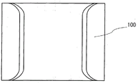
As shown in fig. 1A, the electronic apparatus 100 includes a flexible secondary battery 103 on a curved surface of a support structure body 101 and a display portion 102 on the secondary battery 103.
The support structure 101 is in the shape of a bracelet that bends the belt-like structure. At least a portion of the support structure 101 is flexible and can be opened in the direction of arrow 105; therefore, the electronic device can be worn on the wrist. The end portions of the support structure 101 shown in fig. 1A are bendable, and the central portion far from the end portions is hardly deformed. Therefore, the central portion of the support structure 101 maintains the curvature when the secondary battery and the display portion are attached and fixed in the manufacturing step; thus, even if the electronic apparatus is repeatedly detached and attached, the secondary battery 103 and the display portion 102, which overlap the central portion, are hardly damaged.
In the case where an active matrix display device is provided as a display portion, the active matrix display device has at least a layer including a transistor. The reliability of the layer including the transistor is not easily lowered when the layer is fixed by being attached to the curved surface of the support structure 101. However, the following steps are repeated, and the reliability may be lowered: the layer comprising the transistor is bent in one direction to be concave, back to plane and then in the other direction to be convex. From this point of view, since the central portion of the support structure body 101 shown in fig. 1A is hardly deformed, when the layer including the transistor is fixed to the curved surface of the support structure body 101, even if the layer is bent, the layer is bent only in one direction. In other words, the support structure 101 is used as a protective material that prevents the display portion 102 and the secondary battery 103 from being excessively bent or torsionally deformed.
As a material of the support structure 101, metal, resin, natural material, or the like can be used. The support structure 101 preferably has a thin thickness for light weight. Metal is preferably used as the material of the support structure 101 because metal has high impact resistance and high thermal conductivity. Resin is preferably used as the material of the support structure 101 because resin can achieve weight reduction without causing metal allergy.
The shape of the electronic device shown in fig. 1B is merely an example, and a bracelet or clasp for fixing to a wrist may be provided. Further, the electronic device may be shaped like a ring or a cylinder surrounding the wrist.
Although an example of the electronic device worn on a wrist (including a forearm of the wrist) or an upper arm or the like is shown, there is no particular limitation on a body part, and the electronic device may be worn at any position of the body, such as a waist or an ankle. When the electronic device is worn around the ankle, the electronic device may be manufactured to have a shape different from the shape shown in fig. 1A and 1B and have a size suitable for the shape of the ankle. In the case where the electronic apparatus is worn on the waist, the electronic apparatus may also be manufactured to a size worn on the waist like a belt.
One example of a method of manufacturing the electronic device 100 is shown below.
First, the support structure 101 is prepared. A stainless steel material whose end portions are bendable and hardly deformed in a region having a large radius of curvature in cross section is used for the support structure 101. The stainless steel material is used as a protective material for preventing the display portion 102 and the secondary battery 103 from being excessively bent or twisted. The stainless steel material may only become a certain shape, i.e. bent in one direction when worn on the wrist, which may improve reliability.
Next, a secondary battery 103 attached to a region of the support structure 101 having a large radius of curvature is prepared.
The secondary battery 103 is not particularly limited as long as it is a lithium ion secondary battery and has flexibility. The flexible secondary battery includes a flexible film as an exterior body, and can change in shape according to a curved portion of a region of the support structure body 101 having a large radius of curvature.
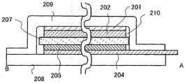
In this embodiment, an example in which a laminate type secondary battery is used as a flexible secondary battery is shown. Fig. 2A shows a plan view of the laminate type secondary battery. Fig. 2B is a schematic sectional view taken along a chain line a-B of fig. 2A.
The secondary battery used is manufactured by stacking a sheet-like positive electrode 203, a separator 207, and a sheet-like negative electrode 206, filling the other regions with an electrolyte 210, and housing these members in an outer package made of one or two films. The positive electrode 203 includes a positive electrode current collector 201 and a positive electrode active material layer 202. The negative electrode 206 includes a negative electrode collector 204 and a negative electrode active material layer 205.
The positive electrode collector 201 and the negative electrode collector 204 can be manufactured using a highly conductive material that is not alloyed with carrier ions such as lithium ions, such as metals including stainless steel, gold, platinum, zinc, iron, nickel, copper, aluminum, titanium, and tantalum, or alloys of these metals. Further, an aluminum alloy to which an element for improving heat resistance, such as silicon, titanium, neodymium, scandium, or molybdenum, is added can be used. In addition, a metal element which reacts with silicon to form silicide may be used. The metal element which reacts with silicon to form a silicide includes zirconium, titanium, hafnium, vanadium, niobium, tantalum, chromium, molybdenum, tungsten, cobalt, nickel, and the like. The positive electrode collector 201 and the negative electrode collector 204 may be in the form of foil, plate (sheet), mesh, cylinder, coil, punched metal mesh, drawn metal mesh, or the like. Both the positive electrode collector 201 and the negative electrode collector 204 preferably have a thickness of 10 μm or more and 30 μm or less.
As the positive electrode active material layer 202, a material capable of inserting and extracting lithium ions can be used. For example, a lithium-containing material having an olivine-type crystal structure, a layered rock-salt-type crystal structure, or a spinel-type crystal structure may be used. As the positive electrode active material, LiFeO can be used2、LiCoO2、LiNiO2、LiMn2O4、V2O5、Cr2O5、MnO2And (e) a compound such as a quaternary ammonium compound.
Lithium-containing materials having an olivine-type crystal structure (with the general formula LiMPO)4Typical examples of (M is one or more of Fe (II), Mn (II), Co (II), Ni (II)) are LiFePO4、LiNiPO4、LiCoPO4、LiMnPO4、LiFeaNibPO4、LiFeaCobPO4、LiFeaMnbPO4、LiNiaCobPO4、LiNiaMnbPO4(a+b≤1,0<a<1,0<b<1)、LiFecNidCoePO4、LiFecNidMnePO4、LiNicCodMnePO4(c+d+e≤1,0<c<1,0<d<1,0<e<1)、LiFefNigCohMniPO4(f+g+h+i≤1,0<f<1,0<g<1,0<h<1,0<i<1)。
LiFePO4It is particularly preferable because it has well-balanced properties required for the positive electrode active material, such as safety, stability, high capacity density, high potential, presence of lithium ions capable of deintercalation at the time of initial oxidation (charging).
Examples of the lithium-containing material having a layered rock salt type crystal structure include lithium cobaltate (LiCoO)2);LiNiO2;LiMnO2;Li2MnO3;LiNi0.8Co0.2O2And NiCo-based lithium-containing materials (with the general formula LiNi)xCo1-xO2(0<x<1));LiNi0.5Mn0.5O2The NiMn lithium-containing material (whose general formula is LiNi)xMn1-xO2(x is more than 0 and less than 1)); and LiNi1/3Mn1/3Co1/3O2An NiMnCo-based lithium-containing material (also called NMC, general formula LiNi)xMnyCo1-x-yO2(x > 0, y > 0, x + y < 1)). Further, examples thereof include Li (Ni)0.8Co0.15Al0.05)O2And Li2MnO3-LiMO2(M=Co、Ni、Mn)。
Examples of the lithium-containing material having a spinel-type crystal structure include LiMn2O4、Li1+xMn2-xO4、Li(MnAl)2O4And LiMn1.5Ni0.5O4。
Preferably, for LiMn2O4And a lithium-containing material having a spinel-type crystal structure containing manganese is mixed with a small amount of lithium nickelate (LiNiO)2Or LiNi1-xMO2(for example, M ═ Co, Al)) because of the advantage that elution of manganese or decomposition of the electrolytic solution is extremely small.
In addition, represented by the general formula Li(2-j)MSiO4Lithium-containing materials represented by (M is one or more of Fe (II), Mn (II), Co (II), Ni (II), and 0. ltoreq. j.ltoreq.2) can be used as positive electrode active materials. Li(2-j)MSiO4Typical examples of (general formula) include lithium compounds such as Li(2-j)FeSiO4、Li(2-j)NiSiO4、Li(2-j)CoSiO4、Li(2-j)MnSiO4、Li(2-j)FekNilSiO4、Li(2-j)FekColSiO4、Li(2-j)FekMnlSiO4、Li(2-j)NikColSiO4、Li(2-j)NikMnlSiO4(k+l≤1,0<k<1,0<l<1)、Li(2-j)FemNinCoqSiO4、Li(2-j)FemNinMnqSiO4、Li(2-j)NimConMnqSiO4(m+n+q≤1,0<m<1,0<n<1,0<q<1)、Li(2-j)FerNisCotMnuSiO4(r+s+t+u≤1,0<r<1,0<s<1,0<t<1,0<u<1)。
In addition, the general formula AxM2(XO4)3NASICON (sodium super ion conductor) compounds represented by (a ═ Li, Na, Mg, M ═ Fe, Mn, Ti, V, Nb, and Al, and X ═ S, P, Mo, W, As, and Si) can be used As the positive electrode active material. Examples of NASICON compounds include Fe2(MnO4)3、Fe2(SO4)3、Li3Fe2(PO4)3. In addition, in the general formula Li2MPO4F、Li2MP2O7、Li5MO4Compounds typified by (M ═ Fe, Mn), perovskite fluorides such as NaF3、FeF3Etc., metal chalcogenides (sulfides, selenides, tellurides) such as TiS2、MoS2Etc. lithium-containing materials such as LiMVO having inverse spinel type crystal structures4Etc., vanadium oxides (e.g., V)2O5、V6O13、LiV3O8) Materials such as manganese oxides and organic sulfur can be used as the positive electrode active material.
The positive electrode active material layer 202 may contain a binder (binder) for improving the adhesion of the active material, a conductive additive for improving the conductivity of the positive electrode active material layer 202, and the like, in addition to the positive electrode active material.
A material capable of dissolving and precipitating lithium or a material that intercalates and deintercalates lithium ions may be used for the anode active material layer 205; for example, lithium metal, carbon-based materials, and alloy-based materials can be used.
The above lithium metals are preferred because of their low redox potential (3.045V lower than the standard hydrogen electrode) and their large specific capacity per weight and volume (3860mAh/g and 2062 mAh/cm)3)。
Examples of the carbon-based material include graphite, easily graphitizing carbon (soft carbon), non-graphitizing carbon (hard carbon), carbon nanotube, graphene, carbon black, and the like.
Examples of the graphite include artificial graphite such as mesocarbon microbeads (MCMB), coke-based artificial graphite (coke-based artificial graphite), pitch-based artificial graphite (pitch-based artificial graphite), and the like, and natural graphite such as spheroidized natural graphite and the like.
Graphite has a low potential (0.1V to 0.3V vs. Li/Li) equivalent to that of lithium metal when lithium ions are intercalated in graphite (upon generation of a lithium-graphite intercalation compound)+). Thus, the lithium ion secondary battery can have a high operating voltage. Further, graphite is preferable because it has advantages of high capacitance per unit volume, small volume expansion, low cost, and high safety compared to lithium metal.
As the negative electrode active material, an alloy material capable of undergoing charge-discharge reaction by alloying reaction with lithium and dealloying reaction can be used. For example, In the case where the carrier ion is a lithium ion, a material containing at least one of Mg, Ca, Al, Si, Ge, Sn, Pb, Sb, Bi, Ag, Au, Zn, Cd, In, Ga, and the like can be used as the alloy-based material. This element has a higher capacitance than carbon. In particular, silicon has a significantly high theoretical capacity of 4200 mAh/g. Thus, silicon is preferably used for the anode active material. Examples of alloy-based materials using such elements include SiO, Mg2Si、Mg2Ge、SnO、SnO2、Mg2Sn、SnS2、V2Sn3、FeSn2、CoSn2、Ni3Sn2、Cu6Sn5、Ag3Sn、Ag3Sb、Ni2MnSb、CeSb3、LaSn3、La3Co2Sn7、CoSb3InSb, SbSn, and the like. Note that SiO means a powder of silicon oxide including a high silicon content portion, and can also be expressed as SiOy(2 > y > 0). Examples of SiO include Si-containing2O3、Si3O4And Si2In OAnd powder of Si and silicon dioxide (SiO)2) A mixture of (a). In addition, the SiO may also include other elements (e.g., carbon, nitrogen, iron, aluminum, copper, titanium, calcium, manganese). That is, SiO means that it contains single crystal Si, amorphous Si, polycrystalline Si, Si2O3、Si3O4、Si2O、SiO2Two or more of the colored materials of (1). Thus, SiO can be derived from SiOx(x is 2 or more) is discriminated as a colorless transparent or white substance. Note that, in the case where a secondary battery is manufactured using SiO as its material, and SiO is oxidized due to repeated charge and discharge, SiO may also be changed to SiO2。
In addition, as the anode active material, an oxide such as titanium dioxide (TiO) may be used2) Lithium titanium oxide (Li)4Ti5O12) Lithium-graphite intercalation compounds (Li)xC6) Niobium pentoxide (Nb)2O5) Tungsten oxide (WO)2) Molybdenum oxide (MoO)2)。
In addition, as the negative electrode active material, Li having a nitride containing lithium and a transition metal may be used3Li of N-type structure3-xMxN (M ═ Co, Ni, Cu). For example, Li2.6Co0.4N3Is preferable because it has a large charge-discharge capacity (900mAh/g and 1890 mAh/cm)3)。
Lithium ions are contained in the negative electrode active material, whereby the negative electrode active material can be used as a positive electrode active material with V as a cathode active material which does not contain lithium ions2O5、Cr3O8When the materials are used in combination, it is preferable to use a nitride of lithium and a transition metal. In the case of using a material containing lithium ions as the positive electrode active material, a nitride containing lithium and a transition metal may be used as the negative electrode active material by previously deintercalating lithium ions contained in the positive electrode active material.
In addition, a material that causes a conversion reaction may be used as the anode active material; for example, cobalt oxide (CoO), nickel oxide (NiO), iron oxide (fe — co), or the like can be used(FeO) and the like which do not alloy with lithium. Other examples of materials that cause the conversion reaction include Fe2O3、CuO、Cu2O、RuO2、Cr2O3Isooxide, CoS0.89Sulfides such as NiS and CuS, and Zn3N2、Cu3N、Ge3N4Iso-nitrides, NiP2、FeP2、CoP3Isophosphide, FeF3、BiF3And the like. Note that the above-described fluorides can be used as the positive electrode active material because they have a high potential.
The anode active material layer 205 may contain, in addition to the anode active material, a binder (binder) for increasing the binding of the active material, a conductive assistant for increasing the conductivity of the anode active material layer 205, and the like.
As the electrolyte in the electrolytic solution 210, a material containing lithium ions as carrier ions is used. A typical example of the electrolyte is a lithium salt, such as LiPF6、LiClO4、Li(FSO2)2N、LiAsF6、LiBF4、LiCF3SO3、Li(CF3SO2)2N、Li(C2F5SO2)2And N is added. These electrolytes may be used either singly or in any combination and ratio of two or more. In order to stabilize the reaction product, a small amount (1 wt%) of Vinylene Carbonate (VC) may be added to the electrolyte to further reduce the decomposition amount of the electrolyte.
As the solvent of the electrolytic solution 210, a material in which carrier ions can move is used. As the solvent of the electrolytic solution, an aprotic organic solvent is preferably used. Typical examples of the aprotic organic solvent include Ethylene Carbonate (EC), propylene carbonate, dimethyl carbonate, diethyl carbonate (DEC), γ -butyrolactone, acetonitrile, ethylene glycol dimethyl ether, tetrahydrofuran, and the like, and one or more of these materials may be used. When a gelled polymer material is used as a solvent for the electrolyte, safety such as liquid leakage resistance is improved. In addition, the secondary battery can be thinned to reduce weight. Typical examples of the gelled polymer material include silicone gel, acrylic glue, acrylonitrile glue, polyethylene oxide, polypropylene oxide, fluorine-based polymer, and the like. Further, by using one or more kinds of ionic liquids (room temperature molten salts) having flame retardancy and low volatility as a solvent of the electrolyte, even if the secondary battery has an internal short circuit or the internal temperature rises due to overcharge or the like, the secondary battery can be prevented from being broken or ignited.
As the separator 207, an insulator such as cellulose (paper), polypropylene having pores, polyethylene having pores can be used.
Fig. 2B shows an example in which the number of electrode layers is 2 (two layers of the positive electrode 203 and the negative electrode 206). In order to reduce the area (size) of the secondary battery while maintaining the capacity of the secondary battery, the size of the secondary battery can be reduced by increasing the number of electrode layers to 2 or more. However, if the number of electrode layers exceeds 40, the thickness of the secondary battery increases, and flexibility may be lost. Therefore, the number of electrode layers is set to 40 or less, preferably 20 or less. In the case of double-sided coating in which both sides of the positive electrode collector are coated with the positive electrode active material layer 202, or in the case of double-sided coating in which both sides of the negative electrode collector 204 are coated with the negative electrode active material layer 205, the number of electrode layers can be reduced to 10 or less while maintaining the capacity of the secondary battery.
The stack including the sheet-like positive electrode 203, the separator 207, and the sheet-like negative electrode 206 is sealed by heat sealing.
In the secondary battery, a flexible film (e.g., a laminate film) is used as an exterior body. The laminated film refers to a laminated film of a base film and an adhesive synthetic resin film or a laminated film of two or more films. As the base film, polyester such as PET or PBT, polyamide such as nylon 6 or nylon 66, inorganic film produced by vapor deposition, or paper can be used. As the adhesive synthetic resin film, polyolefin such as PE or PP, acrylic synthetic resin, epoxy synthetic resin, or the like may be used. The object to be processed is laminated with the laminated film by thermocompression bonding with a laminating apparatus. Further, as a pretreatment for the lamination process, a primer (anchor coat agent) is preferably applied, which can increase the adhesion between the laminated film and the object to be treated. As the anchor coat agent, isocyanates and the like can also be used.
In the present specification, heat sealing refers to sealing by thermocompression bonding, and means melting an adhesive layer of a partial cover substrate film or an outermost layer or an innermost layer of a laminate film having a low melting point by heat and bonding by pressure.
The positive electrode collector 201 and the negative electrode collector 204 also serve as terminals for electrical contact with the outside. Therefore, as shown in fig. 2A, the positive electrode current collector 201 and the negative electrode current collector 204 are arranged such that a part of the positive electrode current collector 201 and the negative electrode current collector 204 is exposed to the outside of the thin film 208 and the exterior body 209. When the number of stacked electrode layers increases, the plurality of positive electrode current collectors 201 are electrically connected by ultrasonic welding, and the plurality of negative electrode current collectors 204 are electrically connected by ultrasonic welding. In fig. 2B, a part of the negative electrode collector 204 extends beyond the outer package 209.
The laminated secondary battery obtained in this way is first bonded to the region of the support structure 101 having a large radius of curvature, and then bonded to the other region. By first bonding to the region having a large radius of curvature, damage to the secondary battery when bonded to the support structure 101 can be suppressed.
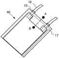
Although fig. 2A shows an example in which the film 208 and the outer package 209 are used for sealing, the present invention is not limited to this example, and a single-layer film folded in half may be used as the outer package. Fig. 10A to 10F show examples different from fig. 2A and 2B. The film 11 is folded in half with its two ends overlapping and the three edges sealed with adhesive layers. The manufacturing method of this example will be described below with reference to fig. 10A to 10F.
First, as shown in fig. 10A, the film 11 is folded in half. Further, a positive electrode current collector 12, a separator 13, and a negative electrode current collector 14, which constitute the secondary battery and are stacked as shown in fig. 10B, are prepared. In addition, two lead electrodes 16 having the sealing layer 15 shown in fig. 10C were prepared. The lead electrode 16 is also referred to as a lead terminal, and is provided for leading out a positive electrode or a negative electrode of the secondary battery to the outside of the exterior body. Then, one of the lead electrodes is electrically connected to the protruding portion of the positive electrode collector 12 by ultrasonic welding or the like. Aluminum is used as a material of the lead electrode connected to the protruding portion of the positive electrode collector 12. The other lead electrode is electrically connected to the protruding portion of the negative electrode collector 14 by ultrasonic welding or the like. Nickel-plated copper is used as a material of the lead electrode connected to the protruding portion of the negative electrode collector 14. Then, both sides of the film 11 are sealed by thermocompression bonding, and one side is opened to put the electrolyte. In the thermal compression, the sealing layer 15 provided on the lead electrode is also melted, whereby the lead electrode and the film 11 are fixed to each other. Then, a desired amount of electrolyte is dropped into the bag-like film 11 under a reduced pressure atmosphere or under an inert atmosphere. Finally, the edge of the film which is not subjected to thermocompression bonding and is still open is sealed by thermocompression bonding. In the above manner, the secondary battery 40 shown in fig. 10D can be manufactured. The end shown by the broken line in fig. 10D is a thermocompression bonding region 17. Fig. 10E shows an example of a cross section along the chain line a-B in fig. 10D. As shown in fig. 10E, the cathode current collector 12, the cathode active material layer 18, the separator 13, the anode active material layer 19, and the anode current collector 14 are stacked in this order and sandwiched between the folded films 11, the ends of the films 11 are sealed by the adhesive layer 30, and the other spaces are provided with the electrolytic solution 20.
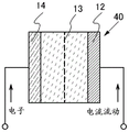
Here, the flow of current during charging of the secondary battery will be described with reference to fig. 10F. When a secondary battery using lithium is regarded as a closed circuit, the migration of lithium ions and the direction in which current flows are the same. Note that, in a secondary battery using lithium, an anode (anode) and a cathode (cathode) are exchanged according to charge and discharge, and an oxidation reaction and a reduction reaction are performed at the corresponding sides; therefore, an electrode having a high oxidation-reduction potential is referred to as a positive electrode, and an electrode having a low oxidation-reduction potential is referred to as a negative electrode. Therefore, in the present specification, the positive electrode is referred to as a "positive electrode" and the negative electrode is referred to as a "negative electrode" at the time of charging, discharging, supplying a reverse pulse current, and supplying a charging current. The use of the names of the anode (anode) and the cathode (cathode) in connection with the oxidation reaction and the reduction reaction may cause confusion because the positions of the anode and the cathode are exchanged with each other at the time of charging and discharging. Therefore, in the present specification, the names of the anode (anode) and the cathode (cathode) are not used. If the names of the anode and the cathode are used, it is necessary to indicate whether charging or discharging is performed, and whether the name corresponds to the positive electrode or the negative electrode.
Two terminals in fig. 10F are connected to a charger, and charge the secondary battery 40. As the charging of the secondary battery 40 proceeds, the potential difference between the electrodes increases. The positive direction in fig. 10F is a direction in which a current flows from one terminal outside the secondary battery 40 to the positive electrode current collector 12, from the positive electrode current collector 12 to the negative electrode current collector 14 in the secondary battery 40, and from the negative electrode current collector 14 to the terminal outside the secondary battery 40. In other words, a current flows in a direction in which the charging current flows.
Next, a display module attached to the secondary battery 103 is prepared. The display module is a display panel mounted with at least an FPC. The display module includes a display unit 102, an FPC104, a driver circuit, and preferably, an inverter for supplying power from a secondary battery 103.
In the display module, the display portion 102 has flexibility, and the display element is provided on a flexible film. The secondary battery 103 and the display unit 102 are preferably arranged to partially overlap each other. When the secondary battery 103 and the display portion 102 are arranged to partially overlap each other, the power path from the secondary battery 103 to the display portion, that is, the wiring distance can be shortened, whereby the power consumption amount can be reduced.
A method of manufacturing a display element over a flexible film includes a method of directly manufacturing a display element over a flexible film, a method of forming a layer having a display element over a rigid substrate such as a glass substrate, removing the substrate by etching, polishing, or the like, and then bonding the layer having a display element and the flexible film to each other, a method of providing a peeling layer over a rigid substrate such as a glass substrate, forming a layer having a display element thereover, separating the rigid substrate from the layer having a display element by using the peeling layer, and then bonding the layer having a display element and the flexible film together, and the like.
In this embodiment, the technique of providing a peeling layer over a rigid substrate such as a glass substrate, which is disclosed in japanese patent application laid-open No. 2003-174153, is used as a manufacturing method capable of performing heat treatment at 400 ℃.
By the technique disclosed in japanese patent application laid-open No. 2003-174153, a transistor including polycrystalline silicon in an active layer or a transistor including an oxide semiconductor layer can be provided over a flexible substrate or a thin film. These transistors are used as switching elements, and an Electroluminescence (EL) element is provided.
In a general structure of an EL element, a layer including a light-emitting organic compound or inorganic compound (hereinafter referred to as a light-emitting layer) is provided between a pair of electrodes, and when a voltage is applied to the element, electrons and holes are injected and transported from the pair of electrodes to the light-emitting layer. When these carriers (electrons and holes) are recombined, an excited state of the light-emitting organic compound or inorganic compound is generated, and light emission is performed when the light-emitting organic compound or inorganic compound returns to a ground state.
In addition, the types of excited states formed by the organic compound are a singlet excited state and a triplet excited state. Light emission in a singlet excited state is referred to as fluorescence, and light emission in a triplet excited state is referred to as phosphorescence.
Such a light emitting element is generally formed of a thin film having a thickness of submicron to several microns. Therefore, such a light emitting element can be manufactured to be thin and light in weight, which is a great advantage. Further, such a light emitting element has another advantage in that the time from the injection of carriers to the emission of light is about several microseconds or less, and thus has a very fast response speed. Further, since sufficient light emission can be obtained with a dc voltage of about several volts to several tens of volts, power consumption is low.
The EL element has a wider viewing angle than the liquid crystal element, and is preferably used as a display element in the display portion 102 when the display region has a curved surface. Further, an EL element is preferably used as a display element in the display portion 102, since the EL element does not require a backlight unlike a liquid crystal element, power consumption, the number of components, and the total thickness can be reduced.
Further, the method of manufacturing a display element on a flexible film is not limited to the above-described method (japanese patent application laid-open No. 2003-174153). The method and material for manufacturing the EL element may be known methods and materials, and therefore, are not mentioned here.
The display device used as the display portion 102 may display only a simple monochrome image or only a number. Therefore, a passive matrix display device can be used, and in this case, a display element can be manufactured over a film having flexibility by a method other than the technique disclosed in japanese patent application laid-open No. 2003-174153.
The display module obtained in the above manner is attached to the secondary battery 103, and the secondary battery 103 and the display unit 102 are electrically connected to each other, whereby the electronic apparatus 100 shown in fig. 1B is completed. Further, a metal cover, a plastic cover, or a rubber cover may be provided in a portion other than the display portion 102 in order to improve the appearance quality of the electronic apparatus 100.
In the case where the electronic apparatus 100 is provided with a display portion, the screen size is not particularly limited as long as it is a size that can be arranged on the support structure. For example, in the case where the electronic device is worn on the wrist, since the circumference of the wrist in the vicinity of the wrist of an adult is 18cm ± 5cm, the maximum value of the screen size is the product of the circumference of the wrist 23cm and the distance from the wrist to the elbow. An adult wrist-to-elbow distance of less than or equal to 1 foot (30.48 cm); therefore, the maximum screen size of the display portion that can be disposed on the cylindrical support structure in the wrist-worn electronic apparatus 100 is 23cm × 30.48 cm. Note that the screen size here does not refer to the size of a curved state, but refers to the size of a flat state. A plurality of display portions may be provided in one electronic apparatus; for example, a second display portion having a smaller size than the first display portion may also be included in the electronic apparatus. The size of the support structure 101 is set larger than the screen size of the display section. In the case of using an EL element, when the screen size of the display portion is a size that can be arranged on the support structure, the total weight of the display panel and the FPC may be greater than or equal to 1g and less than 10 g.
The thickness of the thinnest portion of the electronic apparatus provided with the display portion (the thickness of the support structure body 101, the display portion 102, and the secondary battery 103 overlapping) may be less than or equal to 5 mm. The thickness of the thickest part of the electronic apparatus, i.e., the thickness of the part where the display panel and the FPC are connected to each other, may be less than 1 cm.
The total weight of the electronic device 100 may be less than 100 g.
The electronic device 100 may be worn on the wrist because a portion of the support structure can be opened in the direction of arrow 105 as shown in fig. 1A. The total weight of the electronic device 100 is less than 100g, preferably less than or equal to 50g, and the thickest thickness of the electronic device 100 is very thin, i.e. less than or equal to 1 cm; thereby, a lightweight electronic device can be provided.
The electronic apparatus 100 has a plurality of curved surfaces having different radii of curvature in cross section as shown in fig. 7A. Fig. 7A shows a center of curvature 700 and a center of curvature 701.
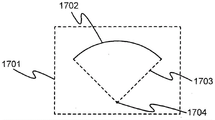
The radius of curvature of the surface is explained with reference to fig. 9A to 9C. In fig. 9A, on a plane 1701 broken along a curved surface 1700, a part of a curve 1702 approximates to a circular arc whose radius serves as a curvature radius 1703 and whose center serves as a curvature center 1704. Fig. 9B is a top view of curved surface 1700. Fig. 9C is a cross-sectional view of curved surface 1700 along plane 1701. When a curved surface is truncated along a plane, the radius of curvature of the curved surface differs according to the plane of truncation. Here, the radius of curvature of the curved surface is defined as the radius of curvature of a curve when the curved surface is truncated along a plane having a curve with the smallest radius of curvature.
When the electronic apparatus 100 having the front-wrist contact surface (exposed back surface) of the exterior body on the inner side thereof and the film surface (exposed surface) of the display panel on the outer side thereof is bent, the curvature radius 1802 of the exterior body 1801 (exposed back surface) in contact with the support structure 1805 on the side close to the center of curvature 1800 of the secondary battery is smaller than the curvature radius 1804 of the film 1803 on the side farther from the center of curvature 1800 (fig. 8A). When the electronic apparatus 100 is bent and has a circular-arc cross section, compressive stress is applied to the exposed back surface of the exterior body close to the center of curvature 1800, and tensile stress is applied to the film surface farther from the center of curvature 1800 (fig. 8B). The electronic apparatus 100 may be deformed such that the radius of curvature of the outer package 1801 on the side close to the center of curvature is 10mm or more, preferably 30mm or more.
The cross-sectional shape of the electronic device 100 is not limited to a simple circular arc shape, and the cross-section of the portion in contact with the wrist may have a circular arc shape; for example, the shape shown in fig. 8C may be used. When the curved surface of the secondary battery is a shape having a plurality of centers of curvature, the electronic apparatus 100 may be deformed into a shape in which the curved surface having the smallest radius of curvature among the radii of curvature corresponding to each of the plurality of centers of curvature, that is, the surface of the exterior body 1801 on the side close to the center of curvature has a radius of curvature of 10mm or more or preferably 30mm or more.
Fig. 7B illustrates a bottom view of the electronic device 100 as viewed from the exposed back side of the support structure. Fig. 7C shows a side view of the electronic device 100.
Embodiment mode 2
In the present embodiment, an example of a method of charging a secondary battery using an antenna will be described.
Since the electronic device is in contact with a part of the body, the input-output terminal of the secondary battery for charging or discharging is preferably not exposed in terms of safety. When the input/output terminal is exposed, the input/output terminal may be short-circuited by water such as rain or the input/output terminal may be in contact with a body to cause an electric shock. A structure in which the input/output terminal is not exposed on the surface of the electronic device can be realized by using the antenna.
This embodiment is the same as embodiment 1 except that an antenna and an RF power supply converter are provided; therefore, other detailed structures are not described herein.
According to embodiment 1, a flexible secondary battery is fixed to a support structure, and a display module is bonded to the secondary battery. An RF power supply converter and an antenna are provided which are electrically connected to the secondary battery. The RF power supply converter is fixed to overlap with a portion of the display section.
The RF power supply converter and the antenna have a weight of 10g or less, and the total weight thereof is almost the same as that of embodiment 1.
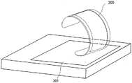
Fig. 3 shows a schematic diagram of an electronic device 300 with an antenna (not shown) and a charger 301. When the electronic apparatus 300 is configured on the charger 301, power may be supplied from the antenna of the charger 301 to the electronic apparatus 300 to charge the secondary battery of the electronic apparatus 300.
Information of the amount or time until full charge, or the like may be displayed on the display portion of the electronic apparatus 300.
This embodiment mode can be freely combined with embodiment mode 1.
Embodiment 3
In this embodiment, an example of a structure for preventing wrinkles or leakage of an electrolyte solution, which may occur when a secondary battery is bent, will be described with reference to fig. 4A and 4B.
In embodiment 1, the secondary battery is sealed by a laminate film, and its periphery is fixed at one place (in cross section). Therefore, if the seal is broken at any portion of the secondary battery when the secondary battery is repeatedly bent or receives an impact, the electrolyte leaks from the inside. In the case where the laminate film is fixed at one portion, bending pressure generated by repeated bending or impact on the secondary battery is concentrated at the portion, whereby the seal cannot be maintained.
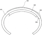
Thus, in the present embodiment, two films are fixed at two portions as shown in fig. 4A. Fig. 4A shows a schematic cross-sectional view of a secondary battery 400 in which a positive electrode and a negative electrode are sealed with two films. By fixing the two portions, the bending pressure is relaxed, and the sealed state can be maintained.
Fig. 4B shows a different configuration example from embodiment 1.
Fig. 4B shows an example in which the display portion 402 is provided on the front surface side of the support structure 401 and the secondary battery 400 is provided on the back surface side thereof.
In fig. 4B, the support structure 401 is provided with an opening through which an FPC403 extending from the display portion 402 and an FPC404 extending from the secondary battery are electrically connected together.
In the present embodiment, the size of the opening provided in the support structure 401 is not particularly limited, and the area of the opening may be larger than that of the display portion 402, and the display portion may be disposed in the opening, as long as a certain degree of mechanical strength can be secured. In this case, the secondary battery 400 and the display portion 402 may be in contact with each other. The larger the opening size, the lighter the weight of the support structure. Thus, the total weight can be reduced.
This embodiment mode can be freely combined with embodiment mode 1.
Example 1
Fig. 5 is a photograph of an electronic device which is manufactured according to embodiment 1, displays an image on a display portion, and is worn on a wrist.
The electronic device shown in fig. 5 is 77mm long, 60mm wide and 57mm high, the dimensions being determined by the stainless steel support structure. The outer dimension of the display panel is 51.5mm × 92.15mm, and the dimension of the display area is 42.12mm × 74.88 mm. The total weight of the electronic device is 40g to 50g, and the total weight of the display panel and the FPC may be about 2 g. In addition, "FPC" in this specification refers to a flexible printed circuit board in which a plurality of metal foil (e.g., Cu, Ni, or Au) patterns are formed on a base material such as polyimide resin or epoxy resin. An Anisotropic Conductive Film (ACF) for pressure bonding is formed along an edge of an end of the FPC so as to cross the ends of the plurality of metal foil patterns arranged. The external connection terminals of the display panel are electrically connected to the FPC by pressure bonding using the ACF provided on the FPC.
As the secondary battery, a laminate type secondary battery was used, and as the positive electrode active material, lithium iron phosphate (LiFePO) was used4). The lithium iron phosphate can improve the safety of the secondary battery.
Fig. 6 is a schematic sectional view of a secondary battery. In this secondary battery, a sheet-like positive electrode collector 601, a sheet-like positive electrode active material layer 602, a separator 607, a negative electrode collector 604, and a negative electrode active material layer 605 are stacked, and the other regions are filled with an electrolyte 610, and these members are surrounded by a film 608 and an exterior body 609 made of a film having a concave portion.
As shown in fig. 6, the number of electrode layers is 16. The structure shown in fig. 6 includes 8 negative electrode current collectors 604 and 8 positive electrode current collectors 601, i.e., 16 layers in total. In addition, in the cross section of the negative electrode lead-out portion shown in fig. 6, 8 layers of negative electrode current collectors 604 were joined by ultrasonic welding.
The thinnest portion of the electronic apparatus provided with the display portion (the thickness at which the support structure, the display portion, and the secondary battery were overlapped) was 3.2 mm. The thickness of the thickest part of the electronic apparatus, that is, the thickness of the part where the display panel is connected to the FPC (the region where the external connection terminals are provided) is 6 mm. Note that an IC chip, a passive electronic element, or the like may also be directly bonded on the FPC. Note that in this case, the IC chip and the like are not regarded as a part of the FPC. In the case where passive electronic components such as L, C, R components, a driver IC chip, a CPU, a memory, and the like are directly bonded to the FPC, there is a possibility that a part thereof is the thickest part of the electronic apparatus.
In the present embodiment, lithium iron phosphate is used as the positive electrode active material. Further reductions in size and weight can be achieved by, for example, appropriately changing the positive electrode active material or the negative electrode active material to increase the volumetric energy density of the secondary battery. For example, when lithium cobaltate (LiCoO)2) When used as a positive electrode active material, the volume energy density is increased. Therefore, when a secondary battery having a capacity equal to that of the present example was manufactured using lithium cobaltate, the secondary battery could be thinner and lighter.
The electric power for displaying an image shown in fig. 5 is supplied only from the secondary battery overlapping with the display portion.
Needless to say, the image displayed on the display portion in fig. 5 is not processed, and is actually displayed in full color. The resolution of the display portion of fig. 5 was 326 ppi. Each pixel includes three transistors, and an oxide semiconductor (InGaO)3(ZnO)m) Are used in these transistors. The connection terminal for charging and displaying image signal input is provided in an end portion of the support structure and is connected with an external charging device or an external driving device when a user does not use the electronic apparatus, that is, when charging or image signal input. When the user uses the electronic apparatus, i.e., wears the electronic apparatus on the wrist to perform display, the cord such as the wiring is not connected to the external drive device.
The electronic device shown in fig. 5 has a total weight of 50g or less and is light when worn on the wrist. In addition, the electronic device provides excellent appearance properties since it can be used as a decoration.
Description of the symbols
100: electronic device, 101: support structure, 102: display unit, 103: secondary battery, 104: FPC, 105: arrow, 201: positive electrode current collector, 202: positive electrode active material layer, 203: positive electrode, 204: negative electrode current collector, 205: negative electrode active material layer, 206: negative electrode, 207: an isolator, 208: film, 209: outer package body, 210: electrolyte, 300: electronic device, 301: charger, 400: secondary battery, 401: support structure, 402: display unit, 403: FPC, 404: FPC, 601: positive electrode current collector, 602: positive electrode active material layer, 604: negative electrode current collector, 605: negative electrode active material layer, 607: spacer, 608: film, 609: outer package body, 610: electrolyte solution
The present application is based on japanese patent application No. 2013-147187 filed by the office on day 16, 7, 2013, the entire content of which is incorporated herein by reference.
Claims (5)
1. A wrist-mounted electronic device comprising:
a structure having a curved cross section;
a secondary battery disposed so as to overlap a central portion of the structure; and
a display portion disposed so as to overlap the secondary battery,
the display section has an electroluminescent element which is provided,
the secondary battery disposed in the structure has a curved cross section,
the display portion disposed in the structure has a curved cross section.
2. A wrist-mounted electronic device comprising:
a structure having a curved cross section;
a secondary battery disposed so as to overlap a central portion of the structure; and
a display portion disposed so as to overlap the secondary battery,
the display section has an electroluminescent element which is provided,
the secondary battery disposed in the structure has a curved cross section,
a cross section of the display portion arranged in the structure is curved,
the display portion is electrically connected to the secondary battery.
3. A wrist-mounted electronic device according to claim 1 or 2,
the cross-sectional shape of the structure is circular arc.
4. An electronic device having:
a structure having a curved cross section;
a secondary battery having a curved cross section and arranged to overlap the structure; and
a display portion disposed so as to overlap the secondary battery,
the secondary battery can be bent along with the structural body when the structural body is mounted.
5. An electronic device having:
a structure having a curved cross section;
a secondary battery having a curved cross section and arranged to overlap the structure; and
a display portion disposed so as to overlap the secondary battery,
the display section has an electroluminescent element which is provided,
the secondary battery can be bent along with the structural body when the structural body is mounted.
Applications Claiming Priority (4)
| Application Number | Priority Date | Filing Date | Title |
|---|---|---|---|
| JP2013-147187 | 2013-07-16 | ||
| JP2013147187 | 2013-07-16 | ||
| PCT/JP2014/068654 WO2015008716A1 (en) | 2013-07-16 | 2014-07-08 | Electronic device |
| CN201480040490.6A CN105393395B (en) | 2013-07-16 | 2014-07-08 | Electronic device |
Related Parent Applications (1)
| Application Number | Title | Priority Date | Filing Date |
|---|---|---|---|
| CN201480040490.6A Division CN105393395B (en) | 2013-07-16 | 2014-07-08 | Electronic device |
Publications (1)
| Publication Number | Publication Date |
|---|---|
| CN114488762A true CN114488762A (en) | 2022-05-13 |
Family
ID=52343407
Family Applications (3)
| Application Number | Title | Priority Date | Filing Date |
|---|---|---|---|
| CN201911098956.9A Active CN111142363B (en) | 2013-07-16 | 2014-07-08 | Electronic device |
| CN201480040490.6A Active CN105393395B (en) | 2013-07-16 | 2014-07-08 | Electronic device |
| CN202111676150.0A Pending CN114488762A (en) | 2013-07-16 | 2014-07-08 | Electronic device |
Family Applications Before (2)
| Application Number | Title | Priority Date | Filing Date |
|---|---|---|---|
| CN201911098956.9A Active CN111142363B (en) | 2013-07-16 | 2014-07-08 | Electronic device |
| CN201480040490.6A Active CN105393395B (en) | 2013-07-16 | 2014-07-08 | Electronic device |
Country Status (7)
| Country | Link |
|---|---|
| US (5) | US9713271B2 (en) |
| JP (8) | JP6483365B2 (en) |
| KR (4) | KR20210076177A (en) |
| CN (3) | CN111142363B (en) |
| DE (1) | DE112014003323T5 (en) |
| TW (5) | TWI757943B (en) |
| WO (1) | WO2015008716A1 (en) |
Families Citing this family (58)
| Publication number | Priority date | Publication date | Assignee | Title |
|---|---|---|---|---|
| USD759010S1 (en) * | 2013-07-12 | 2016-06-14 | Semiconductor Energy Laboratory Co., Ltd. | Portable information terminal |
| USD752042S1 (en) * | 2013-07-12 | 2016-03-22 | Semiconductor Energy Laboratory Co., Ltd. | Portable information terminal |
| JP6426402B2 (en) * | 2013-08-30 | 2018-11-21 | 株式会社半導体エネルギー研究所 | Display device |
| USD753108S1 (en) * | 2013-10-18 | 2016-04-05 | Semiconductor Energy Laboratory Co., Ltd. | Finger ring type portable information terminal |
| USD789928S1 (en) * | 2013-10-21 | 2017-06-20 | Semiconductor Energy Laboratory Co., Ltd. | Wearable device with image display screen |
| KR102407914B1 (en) | 2013-11-28 | 2022-06-13 | 가부시키가이샤 한도오따이 에네루기 켄큐쇼 | Power storage unit and electronic device including the same |
| KR102306495B1 (en) | 2013-12-04 | 2021-09-28 | 가부시키가이샤 한도오따이 에네루기 켄큐쇼 | Power storage unit and electronic device |
| USD767565S1 (en) * | 2013-12-28 | 2016-09-27 | Intel Corporation | Insert for a wearable electronic display device |
| USD730347S1 (en) * | 2014-01-03 | 2015-05-26 | Samsung Electronics Co., Ltd. | Electronic device |
| JP1525592S (en) * | 2014-02-22 | 2015-06-08 | ||
| JP1525593S (en) * | 2014-02-22 | 2015-06-08 | ||
| KR102293958B1 (en) | 2014-02-28 | 2021-08-27 | 가부시키가이샤 한도오따이 에네루기 켄큐쇼 | Electronic device |
| USD751068S1 (en) * | 2014-03-07 | 2016-03-08 | Sony Mobile Communications Ab | Display portion of watch shaped communications equipment |
| KR102568895B1 (en) | 2014-03-13 | 2023-08-21 | 가부시키가이샤 한도오따이 에네루기 켄큐쇼 | Electronic device |
| WO2015173686A1 (en) | 2014-05-16 | 2015-11-19 | Semiconductor Energy Laboratory Co., Ltd. | Electronic device with secondary battery |
| CN110233210B (en) | 2014-05-16 | 2022-04-26 | 株式会社半导体能源研究所 | Electronic device having secondary battery |
| US10586954B2 (en) | 2014-05-23 | 2020-03-10 | Semiconductor Energy Laboratory Co., Ltd. | Electronic device including secondary battery |
| JP2016076475A (en) | 2014-08-06 | 2016-05-12 | 株式会社半導体エネルギー研究所 | Electronic apparatus having secondary battery and spectacle type wearable device |
| JP6671882B2 (en) | 2014-08-08 | 2020-03-25 | 株式会社半導体エネルギー研究所 | Rechargeable battery |
| JP2016057617A (en) | 2014-09-05 | 2016-04-21 | 株式会社半導体エネルギー研究所 | Electronic device |
| JP2016057873A (en) * | 2014-09-10 | 2016-04-21 | コニカミノルタ株式会社 | Thin electronic device |
| JP2016073196A (en) * | 2014-09-26 | 2016-05-09 | 株式会社半導体エネルギー研究所 | Secondary battery module and power supply system |
| JP2016110075A (en) | 2014-10-03 | 2016-06-20 | 株式会社半導体エネルギー研究所 | Light-emitting device, module, and electronic device |
| US10185363B2 (en) | 2014-11-28 | 2019-01-22 | Semiconductor Energy Laboratory Co., Ltd. | Electronic device |
| US11108105B2 (en) | 2015-01-22 | 2021-08-31 | Semiconductor Energy Laboratory Co., Ltd. | Secondary battery and electronic device |
| CN107210478B (en) | 2015-01-23 | 2020-09-08 | 株式会社半导体能源研究所 | Secondary battery and method for manufacturing secondary battery |
| JP6675216B2 (en) | 2015-02-27 | 2020-04-01 | 株式会社半導体エネルギー研究所 | Power storage device |
| KR102350516B1 (en) * | 2015-03-24 | 2022-01-12 | 주식회사 아모그린텍 | Bracelet type Flexible Battery |
| WO2016160703A1 (en) | 2015-03-27 | 2016-10-06 | Harrup Mason K | All-inorganic solvents for electrolytes |
| KR102350451B1 (en) * | 2015-04-10 | 2022-01-12 | 주식회사 아모그린텍 | Bracelet type Flexible Battery |
| US10664020B2 (en) * | 2015-04-23 | 2020-05-26 | Semiconductor Energy Laboratory Co., Ltd. | Electronic device |
| US10263224B2 (en) | 2015-04-23 | 2019-04-16 | Semiconductor Energy Laboratory Co., Ltd. | Power storage device and electronic device |
| US10367176B2 (en) | 2015-05-01 | 2019-07-30 | Semiconductor Energy Laboratory Co., Ltd. | Power storage device and electronic device |
| US10541390B2 (en) | 2015-05-18 | 2020-01-21 | Semiconductor Energy Laboratory Co., Ltd. | Power storage unit and electronic device |
| US9882179B2 (en) | 2015-07-29 | 2018-01-30 | Semiconductor Energy Laboratory Co., Ltd. | Secondary battery and electronic device including secondary battery |
| US10686167B2 (en) | 2015-07-31 | 2020-06-16 | Semiconductor Energy Laboratory Co., Ltd. | Power storage device, battery management unit, and electronic device |
| US9635764B2 (en) * | 2015-09-25 | 2017-04-25 | Intel Corporation | Integrated circuit and method that utilize a shape memory material |
| CN114552083A (en) | 2015-10-27 | 2022-05-27 | 株式会社半导体能源研究所 | Battery and method for manufacturing battery |
| USD783607S1 (en) * | 2016-02-24 | 2017-04-11 | Samsung Electronics Co., Ltd. | Wearable electronic device |
| KR20170101120A (en) | 2016-02-26 | 2017-09-05 | 가부시키가이샤 한도오따이 에네루기 켄큐쇼 | Power storage device, battery management unit, and electronic device |
| CN115509108A (en) | 2016-02-26 | 2022-12-23 | 株式会社半导体能源研究所 | Connecting member, power supply device, electronic apparatus, and system |
| US10784474B2 (en) * | 2016-03-30 | 2020-09-22 | Intel Corporation | Cellular flexible battery cells |
| US10930904B2 (en) | 2016-04-13 | 2021-02-23 | Semiconductor Energy Laboratory Co., Ltd. | Battery module, method for manufacturing battery module, and electronic device |
| US10497982B2 (en) | 2016-05-12 | 2019-12-03 | Semiconductor Energy Laboratory Co., Ltd. | Power storage device and manufacturing method thereof |
| KR102555407B1 (en) * | 2016-06-30 | 2023-07-14 | 엘지디스플레이 주식회사 | Flexible organic light emitting diode display |
| US9837682B1 (en) * | 2016-08-29 | 2017-12-05 | Microsoft Technology Licensing, Llc | Variable layer thickness in curved battery cell |
| US10707531B1 (en) | 2016-09-27 | 2020-07-07 | New Dominion Enterprises Inc. | All-inorganic solvents for electrolytes |
| USD881839S1 (en) * | 2016-11-08 | 2020-04-21 | Muzik Inc. | Wireless earbuds and wearable charger and integrated speaker |
| USD802376S1 (en) * | 2016-12-20 | 2017-11-14 | Ashlee Rivers | Beverage container label |
| WO2018178797A1 (en) * | 2017-03-31 | 2018-10-04 | Semiconductor Energy Laboratory Co., Ltd. | Display device and manufacturing method thereof |
| US11417854B2 (en) * | 2017-10-20 | 2022-08-16 | Pioneer Corporation | Light-emitting device and light-emitting module |
| WO2019240557A1 (en) * | 2018-06-15 | 2019-12-19 | 주식회사 아모그린텍 | Flexible battery and method for forming pattern of flexible battery |
| KR102067377B1 (en) * | 2018-08-06 | 2020-02-11 | 최기은 | Wearable mobile terminal having strap with mounted battary |
| KR102650345B1 (en) | 2018-10-26 | 2024-03-22 | 엘지전자 주식회사 | Flexible led film module |
| CN109669340B (en) * | 2019-02-12 | 2023-09-26 | 浙江吉利控股集团有限公司 | Intelligent watch |
| CN111200177B (en) * | 2020-02-28 | 2021-05-04 | 南京信息工程大学 | Lead-halogen perovskite light-driven charging electrode and preparation method thereof |
| TWD216003S (en) | 2021-05-13 | 2021-12-11 | 樹德科技大學 | Wearable volume control device |
| CN213934556U (en) * | 2021-05-31 | 2021-08-10 | 东莞市无疆科技投资有限公司 | Strapless watch |
Family Cites Families (74)
| Publication number | Priority date | Publication date | Assignee | Title |
|---|---|---|---|---|
| JPS5555380Y2 (en) | 1974-12-24 | 1980-12-22 | ||
| AU563854B2 (en) | 1983-11-30 | 1987-07-23 | Allied Corporation | Spring entrapment of split wedge floatation device |
| US5194857A (en) * | 1991-07-23 | 1993-03-16 | Motorola, Inc. | Pager with rechargeable battery and method for charging same |
| USRE42773E1 (en) * | 1992-06-17 | 2011-10-04 | Round Rock Research, Llc | Method of manufacturing an enclosed transceiver |
| US5416730A (en) * | 1993-11-19 | 1995-05-16 | Appcon Technologies, Inc. | Arm mounted computer |
| US6681014B1 (en) * | 1997-06-02 | 2004-01-20 | Firooz Ghassabian | Wrist-mounted telephone device |
| KR100835757B1 (en) | 1998-10-28 | 2008-06-05 | 비아, 인크 | Flex-to-fixed user interface devices |
| US20040209657A1 (en) * | 1999-01-04 | 2004-10-21 | Yoram Ghassabian | Wrist-mounted telephone device |
| JP4485614B2 (en) | 1999-03-31 | 2010-06-23 | パナソニック株式会社 | Non-aqueous electrolyte battery and manufacturing method thereof |
| JP3794213B2 (en) * | 1999-08-13 | 2006-07-05 | コニカミノルタフォトイメージング株式会社 | Battery built-in belt |
| JP2001266894A (en) | 2000-03-22 | 2001-09-28 | Sony Corp | Electrode for battery and non-aqueous electrolytic battery using it |
| JP2002063938A (en) | 2000-08-18 | 2002-02-28 | Sony Corp | Secondary battery and its manufacturing method |
| JP2002072130A (en) | 2000-08-29 | 2002-03-12 | Shimadzu Corp | Information-displaying device which can be put on man's head |
| JP2002278466A (en) | 2001-03-15 | 2002-09-27 | Minolta Co Ltd | Display device |
| JP4027740B2 (en) | 2001-07-16 | 2007-12-26 | 株式会社半導体エネルギー研究所 | Method for manufacturing semiconductor device |
| US8415208B2 (en) | 2001-07-16 | 2013-04-09 | Semiconductor Energy Laboratory Co., Ltd. | Semiconductor device and peeling off method and method of manufacturing semiconductor device |
| US6673488B2 (en) * | 2001-07-23 | 2004-01-06 | Ngk Spark Plug Co., Ltd. | Packaging for polymer electrolytic cell and method of forming same |
| KR101102116B1 (en) | 2001-10-11 | 2012-01-02 | 디노보 리서치, 엘엘씨 | Digital battery |
| JP3980405B2 (en) | 2002-05-17 | 2007-09-26 | 株式会社東芝 | Image display device |
| TWI351566B (en) | 2003-01-15 | 2011-11-01 | Semiconductor Energy Lab | Liquid crystal display device |
| JP4408044B2 (en) | 2003-01-15 | 2010-02-03 | 株式会社半導体エネルギー研究所 | Method for manufacturing liquid crystal display device |
| GB0302690D0 (en) * | 2003-02-06 | 2003-03-12 | Snapwatch Ltd | Display apparatus |
| JP2004253472A (en) | 2003-02-18 | 2004-09-09 | Fuji Electric Holdings Co Ltd | Solar cell module and its manufacturing process |
| JP2005250442A (en) * | 2004-01-30 | 2005-09-15 | Seiko Epson Corp | Display device, method of controlling display device, control program, and recording medium |
| US20050189906A1 (en) * | 2004-03-01 | 2005-09-01 | Huei-Hsin Sun | Battery arrangement for wrist-carried device |
| CN2752827Y (en) * | 2004-06-11 | 2006-01-18 | 苏伟达 | Multifunction watch |
| JP2008009464A (en) | 2004-10-13 | 2008-01-17 | Tatsuya Hisagane | Card type computer |
| TWM277958U (en) * | 2004-12-31 | 2005-10-11 | Ind Tech Res Inst | An flexible displaying device for electronic information includes a device housing |
| CN200990745Y (en) * | 2005-03-04 | 2007-12-12 | 精工爱普生株式会社 | Personal electronic instrument and portable instrument |
| JP2007078670A (en) | 2005-03-04 | 2007-03-29 | Seiko Epson Corp | Wearable electronic device, method for manufacturing portable device, and the portable device |
| TWI269454B (en) * | 2005-05-25 | 2006-12-21 | Ind Tech Res Inst | Flexible package structure and applications thereof |
| JP2007072434A (en) * | 2005-08-12 | 2007-03-22 | Seiko Epson Corp | Display device |
| JP4977375B2 (en) * | 2006-02-15 | 2012-07-18 | Necエナジーデバイス株式会社 | Lithium ion battery and battery pack using the same |
| JP2008008832A (en) * | 2006-06-30 | 2008-01-17 | Seiko Epson Corp | Timepiece |
| JP2008096543A (en) | 2006-10-06 | 2008-04-24 | Seiko Epson Corp | Display apparatus |
| US7722245B2 (en) | 2006-10-06 | 2010-05-25 | Seiko Epson Corporation | Display device |
| US7518959B2 (en) | 2006-12-01 | 2009-04-14 | Seiko Epson Corporation | Display device and display method |
| JP2008139164A (en) | 2006-12-01 | 2008-06-19 | Seiko Epson Corp | Indication device and indication method |
| US9423995B2 (en) * | 2007-05-23 | 2016-08-23 | Google Technology Holdings LLC | Method and apparatus for re-sizing an active area of a flexible display |
| JP2009087928A (en) | 2007-09-13 | 2009-04-23 | Semiconductor Energy Lab Co Ltd | Semiconductor device and manufacturing method therefor |
| KR101546774B1 (en) * | 2008-07-29 | 2015-08-24 | 엘지전자 주식회사 | Mobile terminal and operation control method thereof |
| JP2010213498A (en) | 2009-03-11 | 2010-09-24 | Omron Corp | Charge controller, method, and program |
| US9401525B2 (en) | 2009-03-20 | 2016-07-26 | Semiconductor Energy Laboratory Co., Ltd. | Power storage device and manufacturing method thereof |
| WO2010128616A1 (en) | 2009-05-02 | 2010-11-11 | Semiconductor Energy Laboratory Co., Ltd. | Electronic book |
| WO2010128614A1 (en) | 2009-05-02 | 2010-11-11 | Semiconductor Energy Laboratory Co., Ltd. | Display device |
| US20100297494A1 (en) * | 2009-05-21 | 2010-11-25 | Chin-Ming Chen | Battery module |
| US9136286B2 (en) | 2009-08-07 | 2015-09-15 | Semiconductor Energy Laboratory Co., Ltd. | Display panel and electronic book |
| JP2011060576A (en) * | 2009-09-10 | 2011-03-24 | Brother Industries Ltd | Wearable lighting fixture |
| KR101172231B1 (en) * | 2009-11-30 | 2012-08-07 | 삼성에스디아이 주식회사 | Protection Tape and Secondary Battery having the same |
| US20120069511A1 (en) * | 2010-03-22 | 2012-03-22 | Azera Paule S | Data storage unit having clasping feature |
| KR101650383B1 (en) * | 2010-04-09 | 2016-08-23 | 엘지전자 주식회사 | Mobile terminal |
| JP5891655B2 (en) * | 2010-08-30 | 2016-03-23 | ソニー株式会社 | Nonaqueous electrolyte battery, nonaqueous electrolyte battery manufacturing method, insulating material, insulating material manufacturing method, battery pack, electronic device, electric vehicle, power storage device, and power system |
| KR20120083804A (en) | 2011-01-18 | 2012-07-26 | 주식회사 팬택 | Portable terminal transformable into the form of a bracelet |
| EP2484243A1 (en) * | 2011-02-08 | 2012-08-08 | Massimo Amenduni Gresele | Wrist belt or bracelet having a timepiece function |
| US20120223593A1 (en) | 2011-03-03 | 2012-09-06 | Semiconductor Energy Laboratory Co., Ltd. | Power receiving device and wireless power supply system |
| TWI420723B (en) | 2011-03-25 | 2013-12-21 | Tex Ray Ind Co Ltd | Wearable battery set |
| JP6107651B2 (en) * | 2011-05-11 | 2017-04-05 | 凸版印刷株式会社 | Lithium ion battery exterior material, lithium ion battery, and method of manufacturing lithium ion battery |
| US9176530B2 (en) * | 2011-08-17 | 2015-11-03 | Apple Inc. | Bi-stable spring with flexible display |
| US20130252065A1 (en) | 2011-08-29 | 2013-09-26 | Panasonic Corporation | Thin battery |
| EP2618411B1 (en) | 2011-08-29 | 2017-02-15 | Panasonic Intellectual Property Management Co., Ltd. | Thin battery electrode group, thin battery, and electronic device |
| JP6041394B2 (en) * | 2011-08-31 | 2016-12-07 | Necエナジーデバイス株式会社 | Non-aqueous electrolyte secondary battery |
| US8929085B2 (en) | 2011-09-30 | 2015-01-06 | Apple Inc. | Flexible electronic devices |
| KR20130069066A (en) * | 2011-12-16 | 2013-06-26 | 삼성전자주식회사 | Display apparatus and display method thereof |
| KR101515629B1 (en) * | 2012-01-07 | 2015-04-27 | 삼성전자주식회사 | Method and apparatus for providing event of portable device having flexible display unit |
| US8947382B2 (en) * | 2012-02-28 | 2015-02-03 | Motorola Mobility Llc | Wearable display device, corresponding systems, and method for presenting output on the same |
| JP5719859B2 (en) | 2012-02-29 | 2015-05-20 | 株式会社半導体エネルギー研究所 | Power storage device |
| US9934713B2 (en) * | 2012-03-28 | 2018-04-03 | Qualcomm Incorporated | Multifunction wristband |
| WO2013191125A1 (en) * | 2012-06-18 | 2013-12-27 | Necエナジーデバイス株式会社 | Film pack battery |
| IL221664A0 (en) * | 2012-08-27 | 2012-12-31 | Yitzchak Dotan | Bipolar battery |
| US9081542B2 (en) * | 2012-08-28 | 2015-07-14 | Google Technology Holdings LLC | Systems and methods for a wearable touch-sensitive device |
| EP2889715B1 (en) * | 2013-12-27 | 2017-07-26 | Panasonic Intellectual Property Management Co., Ltd. | Wearable electronic device |
| US9158285B2 (en) * | 2014-01-06 | 2015-10-13 | Central Standard Timing, LLC | Flexible wristwatch with segmented e-paper display |
| KR102568895B1 (en) * | 2014-03-13 | 2023-08-21 | 가부시키가이샤 한도오따이 에네루기 켄큐쇼 | Electronic device |
| KR20160025830A (en) * | 2014-08-28 | 2016-03-09 | 삼성전자주식회사 | Electronic device |
-
2014
- 2014-07-08 CN CN201911098956.9A patent/CN111142363B/en active Active
- 2014-07-08 KR KR1020217018381A patent/KR20210076177A/en not_active Application Discontinuation
- 2014-07-08 KR KR1020237008796A patent/KR20230042139A/en active IP Right Grant
- 2014-07-08 KR KR1020157036559A patent/KR102267360B1/en active IP Right Grant
- 2014-07-08 WO PCT/JP2014/068654 patent/WO2015008716A1/en active Application Filing
- 2014-07-08 CN CN201480040490.6A patent/CN105393395B/en active Active
- 2014-07-08 KR KR1020197037444A patent/KR102264578B1/en active IP Right Grant
- 2014-07-08 CN CN202111676150.0A patent/CN114488762A/en active Pending
- 2014-07-08 DE DE112014003323.5T patent/DE112014003323T5/en active Pending
- 2014-07-11 US US14/328,947 patent/US9713271B2/en active Active
- 2014-07-11 TW TW109137868A patent/TWI757943B/en not_active IP Right Cessation
- 2014-07-11 TW TW103123933A patent/TWI644196B/en active
- 2014-07-11 TW TW111106932A patent/TW202242602A/en unknown
- 2014-07-11 TW TW107133227A patent/TWI679520B/en active
- 2014-07-11 TW TW108142366A patent/TWI709844B/en active
- 2014-07-16 JP JP2014145944A patent/JP6483365B2/en active Active
- 2014-11-19 JP JP2014234730A patent/JP5727664B2/en active Active
-
2015
- 2015-04-02 JP JP2015076053A patent/JP5755386B1/en active Active
- 2015-05-26 JP JP2015106189A patent/JP6110890B2/en active Active
-
2017
- 2017-07-11 US US15/646,400 patent/US11013132B2/en active Active
-
2019
- 2019-02-14 JP JP2019024166A patent/JP2019133159A/en not_active Withdrawn
-
2020
- 2020-06-09 JP JP2020099984A patent/JP7036865B2/en active Active
-
2021
- 2021-05-17 US US17/321,632 patent/US11317525B2/en active Active
-
2022
- 2022-03-03 JP JP2022032605A patent/JP7344330B2/en active Active
- 2022-04-21 US US17/726,329 patent/US11672086B2/en active Active
-
2023
- 2023-05-31 US US18/204,089 patent/US20230328905A1/en active Pending
- 2023-09-01 JP JP2023141937A patent/JP2023171721A/en active Pending
Also Published As
Similar Documents
| Publication | Publication Date | Title |
|---|---|---|
| JP7344330B2 (en) | Electronics | |
| KR102422019B1 (en) | Electronic device |
Legal Events
| Date | Code | Title | Description |
|---|---|---|---|
| PB01 | Publication | ||
| PB01 | Publication | ||
| SE01 | Entry into force of request for substantive examination | ||
| SE01 | Entry into force of request for substantive examination |