CN114484690B - New forms of energy air purification equipment - Google Patents
New forms of energy air purification equipment Download PDFInfo
- Publication number
- CN114484690B CN114484690B CN202210361678.7A CN202210361678A CN114484690B CN 114484690 B CN114484690 B CN 114484690B CN 202210361678 A CN202210361678 A CN 202210361678A CN 114484690 B CN114484690 B CN 114484690B
- Authority
- CN
- China
- Prior art keywords
- air
- machine body
- motor
- inner shell
- shell
- Prior art date
- Legal status (The legal status is an assumption and is not a legal conclusion. Google has not performed a legal analysis and makes no representation as to the accuracy of the status listed.)
- Active
Links
Images


Classifications
-
- F—MECHANICAL ENGINEERING; LIGHTING; HEATING; WEAPONS; BLASTING
- F24—HEATING; RANGES; VENTILATING
- F24F—AIR-CONDITIONING; AIR-HUMIDIFICATION; VENTILATION; USE OF AIR CURRENTS FOR SCREENING
- F24F8/00—Treatment, e.g. purification, of air supplied to human living or working spaces otherwise than by heating, cooling, humidifying or drying
- F24F8/10—Treatment, e.g. purification, of air supplied to human living or working spaces otherwise than by heating, cooling, humidifying or drying by separation, e.g. by filtering
-
- F—MECHANICAL ENGINEERING; LIGHTING; HEATING; WEAPONS; BLASTING
- F24—HEATING; RANGES; VENTILATING
- F24F—AIR-CONDITIONING; AIR-HUMIDIFICATION; VENTILATION; USE OF AIR CURRENTS FOR SCREENING
- F24F13/00—Details common to, or for air-conditioning, air-humidification, ventilation or use of air currents for screening
- F24F13/28—Arrangement or mounting of filters
-
- F—MECHANICAL ENGINEERING; LIGHTING; HEATING; WEAPONS; BLASTING
- F24—HEATING; RANGES; VENTILATING
- F24F—AIR-CONDITIONING; AIR-HUMIDIFICATION; VENTILATION; USE OF AIR CURRENTS FOR SCREENING
- F24F8/00—Treatment, e.g. purification, of air supplied to human living or working spaces otherwise than by heating, cooling, humidifying or drying
- F24F8/20—Treatment, e.g. purification, of air supplied to human living or working spaces otherwise than by heating, cooling, humidifying or drying by sterilisation
-
- H—ELECTRICITY
- H02—GENERATION; CONVERSION OR DISTRIBUTION OF ELECTRIC POWER
- H02J—CIRCUIT ARRANGEMENTS OR SYSTEMS FOR SUPPLYING OR DISTRIBUTING ELECTRIC POWER; SYSTEMS FOR STORING ELECTRIC ENERGY
- H02J7/00—Circuit arrangements for charging or depolarising batteries or for supplying loads from batteries
- H02J7/34—Parallel operation in networks using both storage and other dc sources, e.g. providing buffering
- H02J7/35—Parallel operation in networks using both storage and other dc sources, e.g. providing buffering with light sensitive cells
Landscapes
- Engineering & Computer Science (AREA)
- Chemical & Material Sciences (AREA)
- Combustion & Propulsion (AREA)
- Mechanical Engineering (AREA)
- General Engineering & Computer Science (AREA)
- Power Engineering (AREA)
- Filtering Of Dispersed Particles In Gases (AREA)
Abstract
The invention discloses new energy air purification equipment, which comprises a wall body, wherein an external machine body is arranged on the outer side of the wall body, a first motor and a first rotating blade are arranged in the external machine body, a metal net sheet is arranged in the external machine body in an array manner, a photovoltaic panel is arranged above the external machine body, an internal machine body is arranged on the inner side of the wall body, the internal machine body is connected with the external machine body through a communication pipeline, an air filter element is inserted in the internal shell, a second motor and a second fan blade are arranged above the air filter element, an auxiliary filter sleeve is sleeved on the second motor, and an air outlet assembly is inserted above the auxiliary filter sleeve. The purified air is discharged to the room.
Description
Technical Field
The invention belongs to the field of air purification, and particularly relates to new energy air purification equipment.
Background
The air purifier is a product capable of adsorbing, decomposing or converting various pollutants (generally including PM2.5, dust, pollen, peculiar smell, formaldehyde and other decoration pollutants, bacteria, allergens and the like) in the air, effectively improving the indoor air cleanliness, and is applied to the fields of home, office, medical treatment and industry, the air purifier mainly has the function of removing particulate matters in the air, including allergens, indoor PM2.5 and the like, and can solve the problem of air pollution caused by decoration or other reasons due to volatile organic matters in rooms, underground spaces and vehicles.
The application of the existing new energy air purification equipment is wide, when the existing air purification equipment is used, the internal filter screen is easy to have the problems of humidity and the like in the long-term adsorption and purification process, substances such as mildew and the like are easy to breed in the humid internal environment, so that the purified air generates peculiar smell, and the use effect of the equipment is influenced, so that a filter device in the purification equipment needs to be cleaned or replaced, and the internal filter screens of most purifiers are difficult to disassemble due to the complex equipment structure, so that the impurities in the purification device are inconvenient to clean and the dust is inconvenient to remove; when the air purifier is used, air is sucked from the outside and then is filtered by the filter screen and then is output, wherein the air stays in the purifier for a short time when the flow speed is too high, and cannot be fully contacted with the temporal filter element and filtered, so that the purification effect is poor, and the health of indoor personnel is influenced; most purifiers adopt a charged lithium battery to supply power to an air suction device of equipment, and a battery power supply needs to be frequently replaced to cause environmental pollution and resource waste.
Therefore, it is necessary to invent a new energy air purifying device aiming at the above problems.
Disclosure of Invention
The invention aims to provide new energy air purification equipment which can be charged by solar energy, has triple filtering effects and is convenient to disassemble and collect dust and sundries.
The technical scheme adopted by the invention for realizing the purpose is as follows:
new forms of energy air purification equipment includes: the wall body is internally provided with a communication pipeline in an inserted mode, an external machine body is arranged on one outdoor side of the wall body, an internal machine body is arranged on one indoor side of the wall body and connected with the internal machine body through the communication pipeline, an outer support frame fixed with the wall body is connected to the bottom surface of the external machine body, the external machine body comprises an external shell, an external machine pipeline hole is formed in one side of the external shell, and a photovoltaic panel which is obliquely arranged is arranged above the external shell; the bottom surface of the inner machine body is connected with an inner support frame fixed with a wall body, the inner machine body comprises an inner shell, an inner machine pipeline hole is formed in one side of the inner shell, air inlet holes are arrayed in the inner shell on the opposite surface of the inner shell, and a storage battery is detachably arranged on the bottom surface of the inner shell. One end of a communication pipeline which is inserted in the wall body is communicated with the external shell through an external machine pipeline hole, the other end of the communication pipeline is communicated with the internal shell through an internal machine pipeline hole, outdoor air can enter the external shell and enter the internal shell through the communication pipeline to be filtered, meanwhile, the internal machine body can also suck indoor air from an air inlet hole to be filtered, the indoor air purification quality is further improved, the external machine body and the internal machine body are fixed on the wall body by the external support frame and the internal support frame and have certain horizontal height, fresh air above the external machine body can conveniently enter the external machine body, meanwhile, the internal machine body and the external machine body are far away from the moist ground, the parts in the device are prevented from being damped and mildewed, a photovoltaic panel arranged above the external shell can collect solar energy and store the energy into a storage battery at the bottom of the internal shell, the working duration of the device is prolonged, the frequency of batteries needing to be changed is reduced, and the photovoltaic panel is obliquely arranged, so that the solar energy can be better obtained and can be converted into the storage battery, the battery is located inside bottom of the body and is reduced the impaired probability of battery on the one hand, and the battery can increase inside bottom of the body's focus stabilizing effect simultaneously, makes inside organism stable not drop on the inner bracing frame.
Preferably, the external shell comprises a first partition plate with a through hole, the first partition plate and the bottom surface of the external shell form a first object collecting cavity, the bottom surface of the external shell is provided with a discharge hole body in an array mode, sponge columns are arranged above the bottom surface of the external shell at intervals, a sponge blade plate is arranged on the side of any sponge column in a surrounding mode, and the sponge blade plate is located right above the discharge hole body. The through holes are formed in the first partition plate, dust and sundries entering the outer shell can conveniently fall into the first collection chamber from the through holes in the first partition plate, the dust and the sundries in the first collection chamber are further discharged to the bottom of the outer shell through the discharge hole body, the phenomenon that air entering the inner shell is excessively turbid due to the fact that too much dust and sundries are accumulated in the outer shell is avoided, the purifying effect is poor, the space of the first collection chamber is filled with the sponge columns and the sponge blade plates arranged in an array mode, the space of the discharge hole body below is limited, the phenomenon that small animals or insects enter the first collection chamber from the discharge hole body and pollute the air is avoided, and on the other hand, the moisture and the water mist transmitted upwards from the bottom surface can be partially absorbed through the sea surface columns and the sponge blade plates, and the air in the outer shell is guaranteed to be pure and have high dryness.
Preferably, metal mesh sheets are arranged above the first partition plate at intervals, metal bending plates are arranged between the adjacent metal mesh sheets, the metal bending plates are connected with the adjacent two metal bending plates through bolts, one side of the outer shell, away from the wall body, is provided with a first shaft hole, the outer shell is fixedly provided with an air guide sleeve at the same side through threaded bolts, a first motor which is inserted between the metal mesh sheets is arranged above the first partition plate, a rotating shaft of the first motor penetrates through the first shaft hole, the tail end of the rotating shaft of the first motor is located in the air guide sleeve, and a first rotating blade is arranged at the tail end of the rotating shaft of the first motor. The first motor is controlled to drive the first rotating blade to rotate to generate spiral air flow, the pressure in the outer shell is smaller than the outside due to the large flow speed in the outer shell, outside air is sucked into the outer shell from the air guide sleeve, the space for the outside air to enter the outer shell is reduced by the first shaft hole, the flow speed of the air flow entering the outer shell is convenient to increase, so that a larger internal and external pressure difference is formed, the speed of the sucked air is increased, the curved surface of the air guide sleeve can guide the air flow entering the outer shell, the metal mesh pieces arranged at intervals on the outer side of the first motor can primarily filter the air flowing to the pipeline hole of the outer motor, the metal mesh pieces can intercept and decelerate the air flow entering the outer shell on one hand, the time of the air flow passing through the metal mesh pieces is prolonged, the filtering effect is improved, and on the other hand, large-sized particulate matters and plant seeds in the air flow passing through the metal mesh pieces can be filtered, first motor sends the heat energy transmission to a plurality of metal mesh piece at the during operation, thereby metal mesh piece gives off the heat with the air current contact that gets into, avoid the overheated burnout of first motor, vibrations energy and the noise transmission that the pivot of first motor produced when rotating to metal mesh piece, metal mesh piece receives the vibrations and drives the metal of setting on this metal mesh piece and bend the board compression swing, the metal is bent the board and is consumed through swing deformation and slow down the vibrations energy, thereby reduce the noise that first motor vibrations sent, and the wobbling metal is bent the board and is driven two metal mesh piece swings and the air contact of adjacent connection, metal mesh piece radiating effect has further been promoted.
Preferably, the air guide sleeve is provided with a water outlet hole at the lowest point of the bottom, and the outermost end of the air guide sleeve is provided with a first filter screen. When external environment is moist or rainwater enters the air guide sleeve, liquid flows to the lowest point along the curved inner wall of the air guide sleeve and is discharged from the water outlet hole, so that the phenomenon that liquid such as rainwater accumulates in the air guide sleeve for a long time to pollute the air entering the external shell is avoided, the first filter screen filters the air entering the air guide sleeve for the first time, leaves, birds and the like are prevented from entering the air guide sleeve and contacting with a first rotating blade in rotation, and the damage of the first rotating blade is caused.
Preferably, a partition plate is arranged below the inner shell, a second object collecting cavity is formed between the partition plate and the bottom surface of the inner shell, the inner shell is communicated with the outside through an opening in one side of the second object collecting cavity, a drawer frame with sliding grooves is arranged at the position of the second object collecting cavity, limiting strips are arranged on two opposite sides of the drawer frame, an object collecting drawer can be arranged in the drawer frame in a sliding mode, limiting sliding grooves are arranged on two sides of the object collecting drawer, the limiting grooves in the two sides respectively slide in the limiting strips on the two sides, through holes are arranged on the partition plate at intervals, air deflectors are arranged above the partition plate at intervals, the air deflectors are hinged to the upper end face of the partition plate, and auxiliary plates are arranged on two sides of any air deflector at intervals. Air in the outer shell enters the upper part of the partition plate from the communicating pipeline, the through holes on the partition plate are convenient for dust in the air to fall into the collection drawer in the second collection cavity, the falling sundries and dust are collected by the collection drawer, the sundries and dust in the collection drawer can be taken out and emptied by sliding on the limiting strips at two sides of the drawer frame through the limiting sliding chutes at two sides of the collection drawer, the dust in the collection drawer is prevented from being lifted when the air enters the inner shell, the air guide plate is a light thin plate and can swing on the partition plate, the auxiliary plate is an elastic part, when the air flow is sucked into the inner shell from the communicating pipeline, the air guide plate is blown by the air flow in the direction of the communicating pipeline and swings to the air inlet hole, when the air guide plate swings down, the inclined air guide plate can form a certain inclination angle with the partition plate under the limitation of the auxiliary plate, and the inclined air flow blown by the communicating pipeline is guided upwards by the inclined air guide plate, the air flow is prevented from being directly output to the indoor through the air inlet hole, the inclined air guide plate can reduce the air flow from entering the collection drawer through the through hole on the partition plate to lift dust on one hand, and the pressure difference caused by the air flow entering the upper portion of the partition plate can drive the dust and sundries in the collection drawer to suspend again on the other hand.
Preferably, the inside casing is equipped with the stopper of two U types, and two relative horizontal plane slopes of stopper are laid on the opposition inner wall of inside casing, offer the spout that is the same inclination with the stopper on the lateral wall of inside casing, and the interlude has air filter in the spout, and the air filter both ends are located the U type inslot of two stoppers respectively, are equipped with the handle baffle on the vertical terminal surface in air filter outside, and handle baffle outline is greater than the spout. Two stoppers are slope opposition setting, air filter can pass the spout and lie in between two stoppers, the air filter both ends are located the U type recess of two stoppers respectively and keep the slope, the aviation baffle is with the air current to slope direction water conservancy diversion to air filter below, the air current filters through the air filter of slope again, the handle baffle is fixed in the air filter outer end, avoid too much air to run out from the gap between air filter and the spout, accessible handle baffle is convenient for pull out air filter washs and changes simultaneously, avoid air filter to use for a long time and go mildy or moist and lose the filter effect.
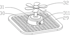
Preferably, an otter board is arranged above the air filter element, the outer edge of the otter board is fixedly connected with the inner wall of the inner shell, a cylindrical motor base is arranged at the center of the otter board downwards, a second motor is arranged inwards in the motor base, a second rotating blade is arranged on a rotating shaft of the second motor in a surrounding mode, a sensor is arranged on the second motor, an auxiliary filter sleeve is arranged on the upper end face of the otter board, the auxiliary filter sleeve is hollow and surrounds a plurality of inner filter plates, the second rotating blade is located between the inner filter plates arranged in the surrounding mode, and inserting grooves are symmetrically formed in the upper portion of the auxiliary filter sleeve. Prevent the second motor through setting up motor base in the otter board, control starts the second motor and drives the second commentaries on classics leaf and rotate and form the spiral air current, form the pressure difference with the external world through the air current velocity of flow in the increase inside casing, on the one hand inhale inside casing with the outside air from the fresh air inlet, on the other hand inhales the inside casing with the gas of intercommunication pipeline, the second commentaries on classics leaf forms the ascending air current that spiral air current drove inside casing and upwards filters through air filter, heat transfer to the otter board of second motor during operation gives off through the otter board, supplementary filter cartridge inner wall encircles the interior filter plate that sets up and carries out secondary filter to the magazine granule in the air current.
Preferably, supplementary filter cartridge top is equipped with the air-out subassembly, and the air-out subassembly includes interior air-out cover, and the interior air-out cover outside is equipped with the air-out cover, and interior air-out cover and the air-out establish the aerofoil between the cover, and the air-out aerofoil encircles and the slope is laid, and the outer wall symmetry of the air-out cover is equipped with the plugboard, and the plugboard is located the inserting groove, and interior air-out cover middle part is sealed and is provided with the sterilamp in the bottom, and the sterilamp is located directly over the second commentaries on classics leaf. The spiral air current that upwards flows can contact the sterilamp, encircle the ascending spiral air current that the interior filter plate that sets up can contact and slow down the second and change the leaf and produce, it promotes the bactericidal effect to improve the time of air current and sterilamp's contact, air current after the sterilization flows upwards from interior air-out cover and the clearance of going out between the wind cover, the air current that the air-out acanthus of surrounding the setting was to flowing through the clearance simultaneously slows down, thereby increase the time that the air current stops in the supplementary filter sleeve, further promote the filter effect, the plugboard can slide from top to bottom in the inserting groove, be convenient for take out and install the air-out subassembly, thereby take out supplementary filter sleeve and wash the change.
The ground selecting device comprises an inner shell, a fan support, a bearing, a rotating shaft, an air outlet fan blade, a display screen and a starting switch. The pivot can be at the bearing internal rotation, the spiral air current that upwards flows from the air-out subassembly blows the air-out flabellum rotatory, thereby the gas outgoing after will purifying, the display screen and the starting switch that the end cover surface set up all are connected with the sensor on the second motor, thereby the display screen can show the rotational speed of second motor and be convenient for the wind-force size of indoor personnel regulation and control inside organism of discharging, the starting switch is as the button of opening and closing the second motor, thereby the end cover passes through the support column and connects the air-out flabellum, thereby it washs the air-out flabellum to be convenient for take out the end cover after long-time the use.
The invention adopts the external machine body and the internal machine body to carry out multiple filtration on air, and collects and converts electric energy through the photovoltaic panel to supply power for the internal machine body and the external machine body, thereby having the following beneficial effects: the first collection chamber is convenient for dust and sundries in the outer shell to fall down and to be discharged out of the outer shell through the discharge hole body, so that the influence of excessive dust accumulation of the outer shell on the quality of air entering the inner machine body can be avoided; the metal mesh filters large particles and dissipates heat and reduces noise of the first motor; after the collection drawer collects sundries and dust in the internal machine body, the collection drawer can be directly taken out to be cleaned, so that the operation is convenient and fast; the air filter element and the auxiliary filter sleeve carry out double filtration on air in the internal machine body, so that the purification effect is improved; the air outlet assembly slows down the wind speed around the sterilizing lamp and the auxiliary filter sleeve, and improves the sterilizing and filtering effects. Therefore, the invention is a new energy air purifying device which can be charged by solar energy, has triple filtering effects and is convenient for disassembling and collecting dust and sundries.
Drawings
FIG. 1 is a schematic view of the overall arrangement of the apparatus;
FIG. 2 is a schematic view of a communication conduit;
FIG. 3 is a schematic view of an outer housing;
FIG. 4 is a schematic view of a sponge column;
FIG. 5 is a schematic view of a metal mesh;
FIG. 6 is a schematic view of the inner housing;
FIG. 7 is a schematic half-section of the inner housing;
FIG. 8 is a schematic view of an air deflector;
FIG. 9 is a schematic view of the chute;
FIG. 10 is a schematic view of a screen;
FIG. 11 is a schematic view of an auxiliary filter sleeve;
FIG. 12 is a schematic view of an air outlet assembly;
FIG. 13 is a schematic view of a germicidal lamp;
fig. 14 is a schematic view of an air outlet fan blade.
Reference numerals: 1. an external body; 10. an outer housing; 11. an outer machine pipe hole; 12. a first shaft hole; 13. an air guide sleeve; 130. a water outlet hole; 14. a first filter screen; 15. a photovoltaic panel; 100. a first separator; 101. a first collection chamber; 102. a discharge hole body; 103. a sponge column; 104. a sponge leaf plate; 105. a metal mesh sheet; 106. a metal bending plate; 107. a first motor; 108. a first rotating blade; 2. an internal body; 20. an inner housing; 21. an inner machine pipe hole; 210. an air inlet hole; 22. a storage battery; 23. a partition plate; 24. a second collection chamber; 240. a drawer frame; 241. a limiting strip; 242. a collection drawer; 243. a limiting chute; 25. An air deflector; 250. an auxiliary plate; 26. a limiting block; 27. a chute; 28. an air filter element; 280. a handle baffle; 29. a screen plate; 30. a motor base; 31. a second motor; 310. a second rotating blade; 311. a sensor; 32. an auxiliary filter sleeve; 320. an inner filter plate; 321. inserting grooves; 33. an air outlet assembly; 330. an inner air outlet sleeve; 331. an outgoing air sleeve; 332. an air outlet blade plate; 333. a plugboard; 334. a sterilizing lamp; 34. an end cap; 340. a support pillar; 341. a fan bracket; 342. a bearing; 343. a rotating shaft; 344. an air outlet fan blade; 35. a display screen; 36. starting a switch; 5. a wall body; 50. a communicating pipe; 51. an outer support frame; 52. an inner support frame.
Detailed Description
The technical scheme of the invention is further described in detail by combining the detailed description and the attached drawings:
it should be apparent that the described embodiments are only some embodiments of the present invention, and not all embodiments. All other embodiments, which can be obtained by a person skilled in the art without making any creative effort based on the embodiments in the present invention, belong to the protection scope of the present invention.
New forms of energy air purification equipment includes: the wall body 5, an outer support frame 51 is fixed on one outdoor side of the wall body 5, an outer machine body 1 is detachably fixed above the outer support frame 51, the outer machine body 1 comprises an outer casing 10, the outer casing 10 is provided with an outer machine pipeline hole 11 at the center of the side wall close to the wall body 5, a communication pipeline 50 is inserted in the wall body 5, one end of the communication pipeline 50, which is positioned outdoors, is fixed on the side wall of the outer casing 10 and is communicated with the outer machine pipeline hole 11, the bottom of the inner wall of the outer casing 10 is provided with a first partition plate 100, through holes are arranged on the first partition plate 100 in an array manner, a first collection chamber 101 is formed between the first partition plate 100 and the bottom surface of the outer casing 10, discharge hole bodies 102 are arranged at the bottom of the outer casing 10 below the first collection chamber 101 in an array manner, a plurality of sponge columns 103 are arranged between the discharge hole bodies 102 on the inner bottom surface of the outer casing 10, sponge columns 103 are provided with sponge blade plates 104 around the side walls, the sponge blade plates 104 are positioned right above the discharge hole bodies 102 closest to the sponge columns 103, dust and sundries carried by air entering the external shell 10 are settled to the first partition plate 100, the dust falls into the first collection chamber 101 through the through holes in the first partition plate 100 and is discharged out of the external shell 10 from the discharge hole body 102 at the bottom of the first collection chamber 101, so that excessive sundries and dust are prevented from accumulating in the first collection chamber 101, the sponge columns 103 and the sponge blade plates 104 in the first collection chamber 101 absorb moisture and water mist flowing upwards on the ground, on the other hand, the sponge blade plates 104 can limit the local space of the discharge hole body 102, and small birds or large insects are prevented from dying and rotting after entering the first collection chamber 101 from the discharge hole body 102 and polluting the air entering the external shell 10.
Metal meshes 105 are arranged above the first partition plate 100 and positioned in the outer shell 10 at intervals, a metal bending plate 106 is connected between every two adjacent metal meshes 105, a first motor 107 is inserted into the metal meshes 105 arranged at intervals, a first rotating blade 108 is arranged on a rotating shaft of the first motor 107 in a surrounding manner, a first shaft hole 12 is arranged on the outer shell 10 and positioned opposite to the outer machine pipeline hole 11, an air guide sleeve 13 is fixed on one side of the outer shell 10, which is provided with the first shaft hole 12, the rotating shaft of the first motor 107 penetrates through the first shaft hole 12, the first rotating blade 108 is positioned in the air guide sleeve 13, a water outlet 130 is arranged at the lowest point of the side wall of the air guide sleeve 13, a first filter screen 14 is arranged on the inner wall of the outermost side of the air guide sleeve 13, a photovoltaic plate 15 attached to the wall 5 is fixed above the outer shell 10, the first rotating blade 108 is controlled to be driven by the first motor 107 to rotate to generate spiral air flow, the flow speed in the outer shell 10 is large, so that the relative pressure in the outer shell 10 is small, and sucks the external air into the outer casing 10 from the air guide sleeve 13, the first axial hole 12 reduces the space for the external air to enter the outer casing 10, so as to increase the flow velocity of the air flow entering the outer casing 10, thereby forming a larger internal and external pressure difference and increasing the speed of sucking the air, the curved surface of the air guide sleeve 13 can guide the air flow entering the outer casing 10, when the external environment is moist or rain enters the air guide sleeve, the liquid flows to the lowest point along the curved inner wall of the air guide sleeve 13 and is discharged from a water outlet hole, so that the liquid such as rain water is prevented from accumulating in the air guide sleeve for a long time to pollute the air entering the outer casing, the first filter screen filters the air entering the air guide sleeve 13 for the first time, the situation that leaves, birds and the like enter the air guide sleeve 13 and contact with the rotating first rotating vane 108 to damage the first vane 108 is avoided, the metal mesh sheets 105 arranged at intervals outside the first motor 107 filter the air flowing to the duct hole 11 of the outer machine, the metal mesh sheets 105 can intercept and decelerate the air flow entering the external shell 10, the time of the air flow passing through the metal mesh sheets 105 is prolonged, so that the primary filtering effect is improved, and on the other hand, large particulate matters and plant seeds in the air flow passing through the metal mesh sheets 105 can be filtered, the first motor 107 can emit heat during working and can be transferred to the plurality of metal mesh sheets 105, the metal mesh sheets 105 are in contact with the entering air flow to emit heat, so that the first motor 107 is prevented from being burnt out due to overheating, vibration energy and noise generated when a rotating shaft of the first motor 107 rotates are transferred to the metal mesh sheets 105, the metal mesh sheets 105 are vibrated and drive the metal bending plates 106 arranged on the metal mesh sheets 105 to compress and swing, the metal bending plates 106 consume and reduce the vibration energy through swinging deformation, so that the noise generated by the vibration of the first motor 107 is reduced, the swinging metal bending plates 106 drive the two adjacent metal mesh sheets 105 to swing and contact with the air, further improving the heat dissipation effect of the metal mesh 105.
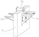
An inner support frame 52 is arranged on one indoor side of a wall body 5, an inner machine body 2 is arranged on the inner support frame 52, the inner support frame 52 and an outer support frame 51 are fixed on the wall body 5 and have a certain horizontal height from the ground, so that fresh air above the inner support frame 52 can conveniently enter an outer machine body 1 and the inner machine body 2, meanwhile, the inner machine body 2 and the outer machine body 1 are far away from the damp ground, and the inner machine body 2 is prevented from being damped and mildewed in the device, the inner machine body 2 comprises an inner shell 20, an inner machine pipeline hole 21 is formed in one side, close to the wall body 5, of the inner shell 20, a communication pipeline 50 is positioned at one indoor end and is fixed on the side wall of the inner shell 20 and is communicated with the inner machine pipeline hole 21, air in the outer shell 10 can enter the inner shell 20 through the communication pipeline 50, air inlet holes 210 are arrayed on the opposite surfaces of the inner machine pipeline hole 21, the air inlet hole 210 are arrayed regions right opposite to the inner machine pipeline hole 21, a storage battery 22 is arranged at the bottom of the inner shell 20, the weight of the bottom of the internal casing 20 is increased by the storage battery 22, so that the center of gravity of the internal casing 20 is lowered, the internal casing 20 is stably and lowly placed on the internal support frame 52, the partition plate 23 is arranged above the bottom surface of the internal casing 20, the outer edge of the partition plate 23 is fixed with the inner wall of the internal casing 20, the second collection chamber 24 is formed between the partition plate 23 and the bottom surface of the internal casing 20, the second collection chamber 24 is communicated with the outside at one side of the adjacent wall 5 and is provided with a drawer frame 240, the upper part of the drawer frame 240 is communicated with the partition plate 23, the two sides of the inner wall of the drawer frame 240 are provided with limit strips 241, a collection drawer 242 is arranged in the drawer frame 240, the two sides of the collection drawer 242 are provided with limit sliding grooves 243 capable of sliding on the limit strips, the air in the external casing 10 enters the upper part of the partition plate 23 from a communication pipeline, through holes on the partition plate 23 are convenient for dust in the air to fall into the collection drawer 242 in the second collection chamber 24, the collection drawer 242 collects falling sundries and dust, the collection drawer 242 can be taken out from the drawer frame 240 and emptied of the sundries and dust, the dust accumulated in the collection drawer is prevented from being kicked up when air enters the inner shell, the limiting strip 241 and the limiting sliding groove 243 guarantee that the collection drawer 242 is pushed and pulled in the horizontal direction, and the collection drawer 242 is prevented from being turned over when pulled out to cause dust to pollute the indoor ground.
The air guide plates 25 are arranged above the partition plate 23 at intervals, the air guide plates 25 are hinged with the upper end face of the partition plate 23, auxiliary plates 250 are arranged at intervals on two sides of any air guide plate 25, the air guide plates 25 are light thin plates and can swing on the partition plate 23, the auxiliary plates 250 are elastic pieces, when air flow is sucked into the inner shell 20 from the communicating pipeline 50, the air guide plates 25 are blown by the air flow in the direction of the communicating pipeline 50 and swing towards the air inlet holes 210, when the air guide plates 25 swing and fall down, the air flow blown by the communicating pipeline 50 is guided upwards by the inclined air guide plates 25 to avoid the air flow from directly outputting to the room through the air inlet holes 210 without being filtered, on one hand, the inclined air guide plates 25 can reduce the probability that the air flow enters the collection drawer 242 through the through holes in the partition plate 23 and lifts dust, on the other hand, the pressure difference caused by the air flow entering the partition plate 23 is prevented from driving the dust and sundries in the collection drawer 242 to suspend again, when the wind speed is higher, the wind pressure on the air deflector 25 is higher, and the pressure difference between the upper side and the lower side of the separation plate 23 is larger, so that the auxiliary plate 250 is pressed down by the air deflector 25 to generate larger elastic deformation, and the inclination angle of the air deflector 25 and the separation plate 23 in the horizontal direction is smaller, thereby better preventing the dust in the collection drawer 242 from rising under the influence of the pressure.
Two U-shaped limiting blocks 26 are arranged on the inner wall of the inner shell 20, the two limiting blocks 26 are obliquely arranged on the opposite inner walls of the inner shell 20 relative to the horizontal plane, the orientation of the U-shaped notches of the two limiting blocks 26 is in the same plane, a sliding groove 27 which has the same inclination angle with the limiting blocks 26 is arranged on the side wall of the inner shell 20, a plate-shaped air filter element 28 is inserted in the sliding groove 27, the air filter element 28 penetrates through the sliding groove 27, two ends of the air filter element 28 are respectively positioned in the U-shaped grooves of the two limiting blocks 26, a handle baffle 280 is arranged on the vertical end surface of the air filter element 28 outside the inner shell 20, the outer contour of the handle baffle 280 is larger than that of the sliding groove 27, the obliquely arranged limiting blocks 26 limit the air filter element 28 and enable the air filter element 28 to be arranged in the inner shell 20 in an oblique state, the air deflector 25 guides the air flow to the lower side of the air filter element 28 along the oblique direction, and the air flow is upwards filtered by the oblique air filter element 28, the handle baffle 280 is fixed to the outer end of the air filter element 28 to prevent excess air from escaping from the gap between the air filter element 28 and the chute 27, and the handle baffle 280 facilitates pulling out the air filter element 28 for cleaning and replacement to prevent the air filter element 28 from losing its filtering effect due to mold or moisture after long-term use. A screen 29 is arranged above the air filter element 28, the outer edge of the screen 29 is fixedly connected with the inner wall of the inner shell 20, a cylindrical motor base 30 is arranged downwards at the center of the screen 29, a second motor 31 is arranged above the motor base 30, a second rotating blade 310 is arranged on a rotating shaft of the second motor 31 in a surrounding manner, a sensor for detecting the rotating speed is arranged on the second motor 31, an auxiliary filter sleeve 32 is erected on the upper end surface of the screen 29, a circular hole is formed in the middle of the auxiliary filter sleeve 32, a plurality of inner filter plates 320 are arranged on the inner wall of the circular hole of the auxiliary filter sleeve 32 in a surrounding manner, the second rotating blade 310 is positioned between the inner filter plates 320 arranged in a surrounding manner, inserting grooves 321 are symmetrically arranged above the auxiliary filter sleeve 32, the second motor 31 is controlled to be started to drive the second rotating blade 310 to rotate to form upward spiral air flow, the pressure difference with the outside is formed by increasing the flow velocity in the inner shell 20, on one hand, the other hand, the outside air is sucked into the inner shell 20 from the air inlet holes 210, on the other hand, the air flow in the external casing 10 is sucked into the internal casing 20 through the communication pipeline 50, the second rotating blade 310 forms an upward spiral air flow to drive the air flow of the internal casing 20 to upwards pass through the air filter element 28 for filtering, the heat generated when the second motor 31 works is transferred to the mesh plate 29 and dissipated through the mesh plate 29, and the inner filter plate 320 arranged around the inner wall of the auxiliary filter sleeve 32 secondarily filters the magazine particles in the air flow, so that the air passing through the auxiliary filter sleeve 32 is further purified.
An air outlet component 33 is arranged above the auxiliary filter sleeve 32, the air outlet component 33 comprises an inner air outlet sleeve 330, an outer air outlet sleeve 331 is arranged outside the inner air outlet sleeve 330, an air outlet blade 332 is arranged between the inner air outlet sleeve 330 and the outer air outlet sleeve 331, the air outlet blade 332 surrounds and is obliquely arranged in a gap between the inner air outlet sleeve 330 and the outer air outlet sleeve 331, four insertion plates 333 are symmetrically arranged on the outer wall of the outer air outlet sleeve 331, each insertion plate 333 is positioned in each insertion groove 321, the middle part of the inner air outlet sleeve 330 is sealed, a sterilizing lamp 334 is arranged at the bottom of the seal, the sterilizing lamp 334 is positioned right above the second rotating blade 310, the second rotating blade 310 rotates to generate spiral air flow, the spiral air flow flowing upwards contacts the sterilizing lamp 334, the surrounding air flow is sterilized and disinfected through the sterilizing lamp 334, the inner filter plate 320 arranged in a surrounding mode can contact and decelerate the spiral air flow upwards generated by the second rotating blade 310, the contact time of the air flow with the sterilizing lamp 334 is prolonged, and the sterilizing effect is improved, the air current after the sterilization upwards flows from the clearance between interior air-out cover 330 and the outer wind cover 331, encircles the air-out acanthus 332 of setting simultaneously and slows down the air current that flows through the clearance to increase the time that the air current stops in the auxiliary filter cover 32, further promote the filter effect, pegboard 333 can slide from top to bottom in inserting groove 321, is convenient for take out and install air-out subassembly 33, thereby takes out auxiliary filter cover 32 and washs the change.
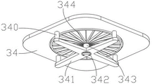
The upper end face of the inner casing 20 is provided with a detachable end cover 34, the center of the end cover 34 is provided with a hole, the bottom edge is provided with support columns 340 symmetrically downwards, a fan bracket 341 is connected between the support columns 340, a bearing 342 is fixed at the center of the fan bracket 341, a rotating shaft 343 is inserted into the inner ring of the bearing 342 and fixed through a shaft shoulder, an air outlet fan blade 344 is arranged around the rotating shaft 343 at a height-control point, the end cover 34 is provided with a display 35 and a start switch 36, the rotating shaft 343 can rotate in the bearing 342, the spiral air flow flowing out from the air outlet assembly 33 blows the air outlet fan blade 344 upwards, the air outlet fan blade 344 drives the rotating shaft 343 to rotate in the bearing 342, the air flow filtered at the lower part is discharged, the rotating air outlet fan blade 344 can prevent objects above the end cover 34 from falling and contacting the second rotating blade 310 to cause damage of the second rotating blade, the sensor 311 detects the rotating speed of the second motor 31 and transmits the data to the display 35 for display, the switch 36 can control the switch of the second motor 31, the end cover 34 is connected to the fan support 341 through the support column 340 to be rotatably connected to the air outlet fan blade 344, the fan support 341 and the air outlet fan blade 344 can be taken out together by taking out the end cover 34, and the air outlet assembly 33 can be taken out by further leaving the inserting groove 321 through the inserting plate 333, so that the auxiliary filter sleeve 32 on the screen plate 29 can be taken out and cleaned conveniently, and the air exhausted by the auxiliary filter sleeve 32 is prevented from being polluted by humidity and mildew after being used for a long time.
It will be evident to those skilled in the art that the invention is not limited to the details of the foregoing illustrative embodiments, and that the present invention may be embodied in other specific forms without departing from the spirit or essential attributes thereof. The present embodiments are therefore to be considered in all respects as illustrative and not restrictive, the scope of the invention being indicated by the appended claims rather than by the foregoing description, and all changes which come within the meaning and range of equivalency of the claims are therefore intended to be embraced therein. Any reference sign in a claim should not be construed as limiting the claim concerned.
Claims (6)
1. New forms of energy air purification equipment includes:
the wall body (5), a communicating pipeline (50) is inserted in the wall body (5), an external machine body (1) is arranged on the outer side of the wall body (5), an internal machine body (2) is arranged on the inner side of the wall body (5), the external machine body (1) is connected with the internal machine body (2) through the communicating pipeline (50),
the method is characterized in that: the bottom surface of the external machine body (1) is connected with an external support frame (51) fixed with the wall body (5), the external machine body (1) comprises an external shell (10), one side of the external shell (10) is provided with an external machine pipeline hole (11), and a photovoltaic panel (15) which is obliquely arranged is arranged above the external shell (10);
The bottom surface of the inner machine body (2) is connected with an inner support frame (52) fixed with the wall body (5), the inner machine body (2) comprises an inner shell (20), an inner machine pipeline hole (21) is formed in one side of the inner shell (20), air inlet holes (210) are arrayed in the inner shell (20) on the opposite surface of the inner machine pipeline hole (21), and a storage battery (22) is detachably arranged on the bottom surface of the inner shell (20);
the air filter is characterized in that the inner shell (20) is provided with two U-shaped limiting blocks (26), the two limiting blocks (26) are obliquely arranged on the opposite inner walls of the inner shell (20) relative to a horizontal plane, the side wall of the inner shell (20) is provided with a sliding groove (27) which has the same inclination angle with the limiting blocks (26), an air filter element (28) is inserted in the sliding groove (27), two ends of the air filter element (28) are respectively positioned in the U-shaped grooves of the two limiting blocks (26), a handle baffle plate (280) is arranged on the vertical end surface of the outer side of the air filter element (28), and the outline of the handle baffle plate (280) is larger than that of the sliding groove (27);
a screen plate (29) is arranged above the air filter element (28), the outer edge of the screen plate (29) is fixedly connected with the inner wall of the inner shell (20), a cylindrical motor base (30) is downwards arranged at the center of the screen plate (29), a second motor (31) is inwards arranged on the motor base (30), a second rotating blade (310) is arranged on a rotating shaft of the second motor (31) in a surrounding mode, a sensor (311) is arranged on the second motor (31), an auxiliary filter sleeve (32) is arranged on the upper end face of the screen plate (29), the auxiliary filter sleeve (32) is hollow and is provided with a plurality of inner filter plates (320) in a surrounding mode, the second rotating blade (310) is located between the inner filter plates (320) in the surrounding mode, and inserting grooves (321) are symmetrically arranged above the auxiliary filter sleeve (32);
The utility model discloses an air-out cover, including air-out cover (330), air-out cover (33), air-out cover (330) are equipped with air-out cover (331) outside the interior air-out cover (330), interior air-out cover (330) with air-out lamina (332) are established between air-out cover (331), air-out lamina (332) encircle and the slope is laid, air-out cover (331) outer wall symmetry is equipped with plugboard (333), plugboard (333) are located in inserting groove (321), interior air-out cover (330) middle part is sealed and is provided with sterilamp (334) in the bottom, sterilamp (334) are located directly over second rotating vane (310).
2. The new energy air purification device as claimed in claim 1, wherein: outside casing (10) include first baffle (100) that have the through-hole that the bottom set up, first baffle (100) with outside casing (10) bottom surface forms first album of thing cavity (101), discharge hole body (102) are seted up to outside casing (10) bottom surface array, outside casing (10) bottom surface top interval sets up sponge post (103), arbitrary sponge post (103) side is encircleed and is provided with sponge acanthus leaf (104), sponge acanthus leaf (104) are located directly over discharge hole body (102).
3. The new energy air purification device as claimed in claim 2, wherein: metal mesh sheet (105) have been laid to first baffle (100) top interval, are equipped with metal board (106) of bending between adjacent metal mesh sheet (105), metal board (106) of bending is through two adjacent metal board (106) of bending of bolted connection, outside casing (10) are kept away from first shaft hole (12) have been seted up to wall body (5) one side, outside casing (10) are fixed with air guide sleeve (13) at the homonymy through the threaded bolt, first baffle (100) top is equipped with and alternates in first motor (107) between metal mesh sheet (105), the pivot of first motor (107) is passed first shaft hole (12) and end are located in air guide sleeve (13), the pivot end of first motor (107) is equipped with first commentaries on classics leaf (108).
4. The new energy air purification device as claimed in claim 3, wherein: the lowest point of the bottom of the air guide sleeve (13) is provided with a water outlet hole (130), and the outermost end of the air guide sleeve (13) is provided with a first filter screen (14).
5. The new energy air purification device as claimed in claim 1, wherein: the inner shell (20) is provided with a partition plate (23) below the inner shell, a second collection chamber (24) is formed between the partition plate (23) and the bottom surface of the inner shell (20), the inner shell (20) is communicated with the outside at one side opening of the second collection chamber (24), a drawer frame (240) with a sliding groove is arranged at the position of the second collection chamber (24), limiting strips (241) are arranged at two opposite sides of the drawer frame (240), a collection drawer (242) is arranged in the drawer frame (240) in a sliding manner, limiting sliding grooves (243) are arranged at two sides of the collection drawer (242), the limiting sliding grooves (243) at two sides respectively slide in the limiting strips (241) at two sides, through holes are distributed at intervals on the partition plate (23), air guide plates (25) are arranged at intervals above the partition plate (23), and the air guide plates (25) are hinged with the upper end surface of the partition plate (23), auxiliary plates (250) are arranged on two sides of any air guide plate (25) at intervals.
6. The new energy air purification device as claimed in claim 1, wherein: inside casing (20) up end is equipped with end cover (34), end cover (34) central opening hole just sets up support column (340) at bottom surface edge symmetry down, be connected with fan bracket (341) between support column (340), fan bracket (341) center department is fixed with bearing (342), it has pivot (343) to alternate in bearing (342), pivot (343) are provided with air-out flabellum (344) in making high point encircleing, be equipped with display screen (35) and starting switch (36) on end cover (34).
Priority Applications (1)
| Application Number | Priority Date | Filing Date | Title |
|---|---|---|---|
| CN202210361678.7A CN114484690B (en) | 2022-04-07 | 2022-04-07 | New forms of energy air purification equipment |
Applications Claiming Priority (1)
| Application Number | Priority Date | Filing Date | Title |
|---|---|---|---|
| CN202210361678.7A CN114484690B (en) | 2022-04-07 | 2022-04-07 | New forms of energy air purification equipment |
Publications (2)
| Publication Number | Publication Date |
|---|---|
| CN114484690A CN114484690A (en) | 2022-05-13 |
| CN114484690B true CN114484690B (en) | 2022-06-28 |
Family
ID=81488061
Family Applications (1)
| Application Number | Title | Priority Date | Filing Date |
|---|---|---|---|
| CN202210361678.7A Active CN114484690B (en) | 2022-04-07 | 2022-04-07 | New forms of energy air purification equipment |
Country Status (1)
| Country | Link |
|---|---|
| CN (1) | CN114484690B (en) |
Family Cites Families (10)
| Publication number | Priority date | Publication date | Assignee | Title |
|---|---|---|---|---|
| JP2579224Y2 (en) * | 1993-12-24 | 1998-08-20 | 日本スピンドル製造株式会社 | Filter device with fan |
| CN2470718Y (en) * | 2000-09-28 | 2002-01-09 | 盛昭俊 | Unit-type air-processing apparatus |
| CN204478285U (en) * | 2015-03-20 | 2015-07-15 | 湖北理工学院 | A kind of energy-saving separating domestic air purifier |
| CN206890704U (en) * | 2017-06-19 | 2018-01-16 | 刘华丽 | A kind of air purifier |
| CN208112396U (en) * | 2018-03-07 | 2018-11-16 | 扬州知行动力科技有限公司 | A kind of good switched reluctance machines of heat dissipation performance |
| CN110469914A (en) * | 2019-08-05 | 2019-11-19 | 广东美的制冷设备有限公司 | Air conditioner |
| CN110805971A (en) * | 2019-10-12 | 2020-02-18 | 上海市政工程设计研究总院(集团)有限公司 | Device for isolating indoor and outdoor air and synchronously generating ions |
| CN210839167U (en) * | 2019-11-25 | 2020-06-23 | 扬州锦盛机电制造有限公司 | Alternating-current single-phase asynchronous motor |
| CN213245411U (en) * | 2020-07-02 | 2021-05-21 | 中创建声环保工程(北京)有限公司 | Ultra-silent fresh air system |
| CN213747085U (en) * | 2020-11-04 | 2021-07-20 | 江苏宏翔通风净化工程有限公司 | Total heat exchange fresh air unit |
-
2022
- 2022-04-07 CN CN202210361678.7A patent/CN114484690B/en active Active
Also Published As
| Publication number | Publication date |
|---|---|
| CN114484690A (en) | 2022-05-13 |
Similar Documents
| Publication | Publication Date | Title |
|---|---|---|
| CN208694595U (en) | A kind of novel public place gas purifying equipment | |
| CN205227572U (en) | Indoor air purifier | |
| CN109737076B (en) | Bladeless fan with air filtering function and filtering control method | |
| CN209588231U (en) | A kind of air purifier with disinfecting and sterilizing functions | |
| CN213020188U (en) | Indoor air purifier | |
| CN114484690B (en) | New forms of energy air purification equipment | |
| CN112728697A (en) | Indoor air purifier with dust collection mechanism at bottom | |
| CN115316284B (en) | Livestock-raising ventilation equipment with adjustable | |
| CN207694508U (en) | A kind of air cleaning unit of cleaning easy to disassemble | |
| CN209204963U (en) | It is a kind of indoor except formaldehyde plant | |
| CN215876646U (en) | New forms of energy air purification device | |
| CN213221561U (en) | Glass steel workshop is with high-efficient gas removal structure | |
| CN115531994A (en) | Efficient energy-saving bidirectional waste gas treatment equipment and use method thereof | |
| CN210905381U (en) | Medical air filter | |
| CN211537103U (en) | Air purification adsorption equipment | |
| CN211450669U (en) | Dust removal street lamp | |
| CN110906474B (en) | Air inlet and outlet device for air purifier based on cross occlusion | |
| CN209254385U (en) | A kind of air dedusting purifier | |
| CN211177221U (en) | Suspension type domestic air purifier | |
| CN220572935U (en) | High-efficient bag collector | |
| CN220878160U (en) | High-efficiency filter screen for filter | |
| CN220689336U (en) | Air purification device based on nanometer photocatalysis | |
| CN218620483U (en) | Second-stage aerobic tank | |
| CN219848685U (en) | Dust collector for boiler | |
| CN217330149U (en) | Improvement type air purifier |
Legal Events
| Date | Code | Title | Description |
|---|---|---|---|
| PB01 | Publication | ||
| PB01 | Publication | ||
| SE01 | Entry into force of request for substantive examination | ||
| SE01 | Entry into force of request for substantive examination | ||
| GR01 | Patent grant | ||
| GR01 | Patent grant | ||
| PP01 | Preservation of patent right |
Effective date of registration: 20221009 Granted publication date: 20220628 |
|
| PP01 | Preservation of patent right | ||
| PD01 | Discharge of preservation of patent |
Date of cancellation: 20230118 Granted publication date: 20220628 |
|
| PD01 | Discharge of preservation of patent |