CN114483487A - Nacelle for a wind turbine and method of supporting torque in such a nacelle - Google Patents
Nacelle for a wind turbine and method of supporting torque in such a nacelle Download PDFInfo
- Publication number
- CN114483487A CN114483487A CN202111266846.6A CN202111266846A CN114483487A CN 114483487 A CN114483487 A CN 114483487A CN 202111266846 A CN202111266846 A CN 202111266846A CN 114483487 A CN114483487 A CN 114483487A
- Authority
- CN
- China
- Prior art keywords
- nacelle
- drive train
- torque arms
- torque
- axis
- Prior art date
- Legal status (The legal status is an assumption and is not a legal conclusion. Google has not performed a legal analysis and makes no representation as to the accuracy of the status listed.)
- Pending
Links
- 238000000034 method Methods 0.000 title claims abstract description 32
- 239000000463 material Substances 0.000 description 5
- 230000008901 benefit Effects 0.000 description 3
- 230000007246 mechanism Effects 0.000 description 3
- 229920001971 elastomer Polymers 0.000 description 2
- 239000000806 elastomer Substances 0.000 description 2
- 238000009434 installation Methods 0.000 description 2
- 238000012986 modification Methods 0.000 description 2
- 230000004048 modification Effects 0.000 description 2
- 230000009286 beneficial effect Effects 0.000 description 1
- 230000008859 change Effects 0.000 description 1
- 238000006243 chemical reaction Methods 0.000 description 1
- 238000010276 construction Methods 0.000 description 1
- 230000006870 function Effects 0.000 description 1
- 230000004044 response Effects 0.000 description 1
Images


Classifications
-
- F—MECHANICAL ENGINEERING; LIGHTING; HEATING; WEAPONS; BLASTING
- F03—MACHINES OR ENGINES FOR LIQUIDS; WIND, SPRING, OR WEIGHT MOTORS; PRODUCING MECHANICAL POWER OR A REACTIVE PROPULSIVE THRUST, NOT OTHERWISE PROVIDED FOR
- F03D—WIND MOTORS
- F03D80/00—Details, components or accessories not provided for in groups F03D1/00 - F03D17/00
- F03D80/80—Arrangement of components within nacelles or towers
- F03D80/88—Arrangement of components within nacelles or towers of mechanical components
-
- F—MECHANICAL ENGINEERING; LIGHTING; HEATING; WEAPONS; BLASTING
- F03—MACHINES OR ENGINES FOR LIQUIDS; WIND, SPRING, OR WEIGHT MOTORS; PRODUCING MECHANICAL POWER OR A REACTIVE PROPULSIVE THRUST, NOT OTHERWISE PROVIDED FOR
- F03D—WIND MOTORS
- F03D80/00—Details, components or accessories not provided for in groups F03D1/00 - F03D17/00
-
- F—MECHANICAL ENGINEERING; LIGHTING; HEATING; WEAPONS; BLASTING
- F03—MACHINES OR ENGINES FOR LIQUIDS; WIND, SPRING, OR WEIGHT MOTORS; PRODUCING MECHANICAL POWER OR A REACTIVE PROPULSIVE THRUST, NOT OTHERWISE PROVIDED FOR
- F03D—WIND MOTORS
- F03D15/00—Transmission of mechanical power
-
- F—MECHANICAL ENGINEERING; LIGHTING; HEATING; WEAPONS; BLASTING
- F03—MACHINES OR ENGINES FOR LIQUIDS; WIND, SPRING, OR WEIGHT MOTORS; PRODUCING MECHANICAL POWER OR A REACTIVE PROPULSIVE THRUST, NOT OTHERWISE PROVIDED FOR
- F03D—WIND MOTORS
- F03D7/00—Controlling wind motors
- F03D7/02—Controlling wind motors the wind motors having rotation axis substantially parallel to the air flow entering the rotor
- F03D7/0204—Controlling wind motors the wind motors having rotation axis substantially parallel to the air flow entering the rotor for orientation in relation to wind direction
-
- F—MECHANICAL ENGINEERING; LIGHTING; HEATING; WEAPONS; BLASTING
- F05—INDEXING SCHEMES RELATING TO ENGINES OR PUMPS IN VARIOUS SUBCLASSES OF CLASSES F01-F04
- F05B—INDEXING SCHEME RELATING TO WIND, SPRING, WEIGHT, INERTIA OR LIKE MOTORS, TO MACHINES OR ENGINES FOR LIQUIDS COVERED BY SUBCLASSES F03B, F03D AND F03G
- F05B2240/00—Components
- F05B2240/10—Stators
- F05B2240/14—Casings, housings, nacelles, gondels or the like, protecting or supporting assemblies there within
-
- F—MECHANICAL ENGINEERING; LIGHTING; HEATING; WEAPONS; BLASTING
- F16—ENGINEERING ELEMENTS AND UNITS; GENERAL MEASURES FOR PRODUCING AND MAINTAINING EFFECTIVE FUNCTIONING OF MACHINES OR INSTALLATIONS; THERMAL INSULATION IN GENERAL
- F16C—SHAFTS; FLEXIBLE SHAFTS; ELEMENTS OR CRANKSHAFT MECHANISMS; ROTARY BODIES OTHER THAN GEARING ELEMENTS; BEARINGS
- F16C2360/00—Engines or pumps
- F16C2360/31—Wind motors
-
- Y—GENERAL TAGGING OF NEW TECHNOLOGICAL DEVELOPMENTS; GENERAL TAGGING OF CROSS-SECTIONAL TECHNOLOGIES SPANNING OVER SEVERAL SECTIONS OF THE IPC; TECHNICAL SUBJECTS COVERED BY FORMER USPC CROSS-REFERENCE ART COLLECTIONS [XRACs] AND DIGESTS
- Y02—TECHNOLOGIES OR APPLICATIONS FOR MITIGATION OR ADAPTATION AGAINST CLIMATE CHANGE
- Y02E—REDUCTION OF GREENHOUSE GAS [GHG] EMISSIONS, RELATED TO ENERGY GENERATION, TRANSMISSION OR DISTRIBUTION
- Y02E10/00—Energy generation through renewable energy sources
- Y02E10/70—Wind energy
- Y02E10/72—Wind turbines with rotation axis in wind direction
Abstract
The invention relates to a nacelle for a wind turbine and a method of supporting torque in the nacelle. Concretely, a nacelle for a wind turbine, the nacelle comprising: the system includes a drive train with a drive train axis, at least two torque arms positioned about the drive train axis and attached to components of the drive train, and a frame attached to a yaw bearing. Torque arms of the drive train are supported by the frame, and at least one of the torque arms has an orientation that at least substantially deviates from horizontal.
Description
Technical Field
The present subject matter relates generally to wind turbines, and more particularly to a nacelle for a wind turbine, the nacelle comprising at least two torque arms fixedly attached to components of a drive train of the nacelle.
Background
Wind power is considered one of the cleanest, most environmentally friendly energy sources presently available, and wind turbines have gained increased attention in this regard. Modern wind turbines typically include a tower, generator, gearbox, nacelle, and one or more rotor blades. The rotor blades derive kinetic energy from the wind using known airfoil principles, and transmit the kinetic energy through rotational energy to turn a shaft that couples the rotor blades to a gearbox, or directly to a generator if a gearbox is not used. The generator then converts the mechanical energy to electrical energy that may be deployed to a utility grid.
Typically, the nacelle comprises a torque arm for transferring forces for supporting the torque of the wind turbine. The torque arm is attached to a component of the drive train, such as to a gearbox. The torque arm may reduce the space available within the nacelle for walkways, exit routes, and material handling. This may result in a nacelle having a larger volume, in particular having a larger width or height.
Accordingly, the present disclosure is directed to a nacelle for a wind turbine, the nacelle comprising at least two torque arms fixedly attached to components of a drive train of the nacelle.
Disclosure of Invention
Aspects and advantages of the invention will be set forth in part in the following description, or may be obvious from the description, or may be learned through practice of the invention.
In one aspect, the present disclosure is directed to a nacelle for a wind turbine. The nacelle includes: the system includes a drive train with a drive train axis, at least two torque arms positioned about the drive train axis and attached to components of the drive train, and a frame attached to a yaw bearing. Torque arms of the drive train are supported by the frame, and at least one of the torque arms has an orientation that at least substantially deviates from horizontal. In an exemplary embodiment, the torque arm is supported by the frame using a damper. It should be appreciated that the nacelle may further include any additional features as described herein.
In another aspect, the present disclosure is directed to a method of supporting torque in a nacelle of a wind turbine having a drive train with a drive train axis. The method comprises the following steps: at least two torque arms are provided positioned about the drive train axis and attached to components of the drive train, and a frame is provided attached to the yaw bearing. Torque arms of the drive train are supported by the frame, and at least one of the torque arms has an orientation that at least substantially deviates from horizontal. It should be understood that the method may further include any additional steps and/or features as described herein.
These and other features, aspects, and advantages of the present invention will be further supported and described with reference to the following description and appended claims. The accompanying drawings, which are incorporated in and constitute a part of this specification, illustrate embodiments of the invention and together with the description, serve to explain the principles of the invention.
Technical solution 1. a nacelle for a wind turbine, the nacelle comprising:
a drive train with a drive train axis;
at least two torque arms positioned about the drive train axis and attached to components of the drive train; and
a frame attached to the yaw bearing, wherein
Torque arms of the drive train are supported by the frame, and wherein at least one of the torque arms has an orientation that at least substantially deviates from horizontal.
Solution 2. the nacelle of solution 1 wherein at least one of the torque arms has an orientation that is at least 10 ° off horizontal.
Solution 3. the nacelle of any of the preceding solutions, wherein two of the torque arms are at least substantially offset from being parallel to each other.
Claim 4 the nacelle of any of claims 1 or 2, wherein at least one of the torque arms is non-linear.
Claim 5 the nacelle of any of claims 1 or 2, wherein at least one of the torque arms includes a first section extending from the member in a first direction and a second section continuing from the first section in a second direction, wherein an angle between the first direction and the second direction is greater than 10 °.
Claim 6 the nacelle according to any one of claim 1 or claim 2, wherein at least one of the torque arms is supported by the frame from above.
Claim 8 the nacelle of any of claims 1 or 2, configured such that in an installed state, a distance between the drive train axis and a yaw axis is greater than 1 cm.
Solution 9. a method of supporting torque in a nacelle of a wind turbine having a drive train with a drive train axis, the method comprising:
providing at least two torque arms positioned about the drive train axis and attached to a component of the drive train; and
providing a frame attached to a yaw bearing, wherein torque arms of the drive train are supported by the frame, and wherein at least one of the torque arms has an orientation that at least substantially deviates from horizontal.
Claim 10 the method of claim 9 wherein at least one of the torque arms has an orientation that is at least 10 ° off horizontal.
Claim 11 the method of any of claims 9-10 wherein two of the torque arms are at least substantially offset from being parallel to each other.
The method of any of claims 9-10 wherein at least one of the torque arms is supported from below by the frame.
Claim 15 the method of any of claims 9-10 wherein at least one of the torque arms is supported in at least one of a lateral direction and a longitudinal direction relative to the driveline axis.
Drawings
A full and enabling disclosure of the present invention, including the best mode thereof, directed to one of ordinary skill in the art, is set forth in the specification, which makes reference to the appended figures, in which:
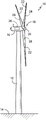
FIG. 1 illustrates a perspective view of a wind turbine;
FIG. 2 shows a simplified interior view of a nacelle of a wind turbine, in particular illustrating the nacelle during normal operation;
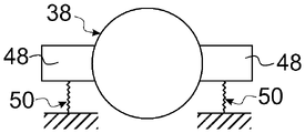
3A-B respectively show a schematic view of a part of a nacelle according to the prior art;
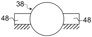
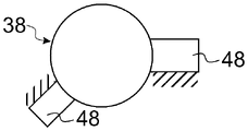
4A-E respectively illustrate a schematic view of a portion of a nacelle according to an embodiment of the disclosure;
FIG. 5 shows a schematic view of a portion of a nacelle according to an embodiment of the disclosure; and
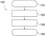
FIG. 6 shows a flow chart of an embodiment of a method of supporting torque in a nacelle of a wind turbine according to the present disclosure.
Detailed Description
Reference now will be made in detail to embodiments of the invention, one or more examples of which are illustrated in the drawings. Each example is provided by way of explanation of the invention, not limitation of the invention. In fact, it will be apparent to those skilled in the art that various modifications and variations can be made in the present invention without departing from the scope or spirit of the invention. For instance, features illustrated or described as part of one embodiment, can be used with another embodiment to yield a still further embodiment. It is therefore intended that the present invention cover such modifications and variations as come within the scope of the appended claims and their equivalents.
Referring now to the drawings, FIG. 1 illustrates a perspective view of a wind turbine 10. As shown, wind turbine 10 generally includes a tower 12 extending from a support surface 14, a nacelle 16 mounted on tower 12, and a rotor 18 coupled to nacelle 16. Thus, the nacelle 16 corresponds to the overall housing structure and has a bottom wall, opposing side walls, a front wall, a rear wall, and a top wall. Further, the front wall may have a spindle opening configured to receive a spindle 34 (fig. 2) therethrough, which may be connected to the rotor 18.
As shown in FIG. 1, rotor 18 includes a rotatable hub 20 and at least one rotor blade 22 coupled to hub 20 and extending outwardly from hub 20. For example, in FIG. 1, rotor 18 includes three rotor blades 22. However, in alternative wind turbines, rotor 18 may include more or less than three rotor blades 22. Each rotor blade 22 may be spaced about hub 20 to facilitate rotating rotor 18 to enable kinetic energy to be transferred from the wind into usable mechanical energy, and subsequently, electrical energy. For example, hub 20 may be rotatably coupled to a generator 24 (FIG. 2) positioned within nacelle 16 to allow electrical energy to be generated.
Referring now to FIG. 2, a simplified interior view of an exemplary nacelle 16 of wind turbine 10 shown in FIG. 1 is illustrated, particularly illustrating drive train components thereof. More specifically, as shown, generator 24 may be coupled to rotor 18 for generating electrical power from the rotational energy generated by rotor 18. Rotor 18 may be coupled to a main shaft 34, and main shaft 34 may rotate via a main bearing (not shown). The main shaft 34, in turn, may be rotatably coupled to a gearbox output shaft 36 of the generator 24 through the gearbox 30. The gearbox 30 may include a gearbox housing 38, with the gearbox housing 38 connected to the bedplate 46 by one or more torque arms 48. More specifically, in certain wind turbines, bedplate 46 may be a forged component in which a main bearing (not shown) is located and through which main shaft 34 extends. As is generally understood, main shaft 34 provides a low speed, high torque input to gearbox 30 in response to rotation of rotor blades 22 and hub 20. Thus, the gearbox 30 thus converts the low speed, high torque input to a high speed, low torque output to drive the gearbox output shaft 36, and thus the generator 24.
Each rotor blade 22 may also include a pitch adjustment mechanism 32 configured to rotate each rotor blade 22 about its pitch axis 28 via a pitch bearing 40. Similarly, wind turbine 10 may include one or more yaw drive mechanisms 42 communicatively coupled to controller 26, wherein each yaw drive mechanism 42 is configured to change an angle of nacelle 16 with respect to the wind (e.g., by engaging a yaw bearing 44 of wind turbine 10).
In some embodiments, the wind turbine may be an onshore wind turbine. In several embodiments, the wind turbine may be an off-shore wind turbine.
In some embodiments, components of a wind turbine may include mechanical, electrical, or electromechanical devices specifically associated with energy generation or conversion. In embodiments, the component may comprise at least one of a drive train, a drive train component and a transformer. Specifically, the drive train components may include a gearbox, a main shaft, a main bearing, and/or a generator.
In some embodiments, the nacelle may include a base coupled to a tower of the wind turbine. The base may comprise at least a part of the floor and/or the bottom wall of the nacelle. In some embodiments, the roof may be configured to be mounted to the base of the nacelle, in particular using releasable connection means, for example by active locking of the roof and the base or via fasteners such as bolts.
Fig. 3A-B show a schematic view of a part of a nacelle according to the prior art, respectively. For clarity, only the torque arm 48 and the gearbox 38 are shown. For example, the remaining configuration of the nacelle may be as described above with respect to FIG. 2.
In fig. 3A, the torque arm 48 is directly attached to the gear box 38. The torque arm 48 is supported by the frame of the nacelle via an elastomer 50. Specifically, an elastomeric body 50 is disposed between each torque arm and the frame.
In fig. 3B, an elastomer (not shown) is disposed between the torque arm 48 and the gear case 38 as a damper. In this example, the torque arm is directly supported by the frame. The use of a damper between the frame and the torque arm is also commonly understood as a direct support. In fig. 3A-B, the support areas are represented by shaded areas.
As can be seen, the orientation of the torque arm 48 in fig. 3A-B is at least substantially horizontal. Specifically, the torque arm 48 is positioned symmetrically about the drive train axis of the nacelle. More specifically, the plane of symmetry is oriented vertically and parallel to the drive train axis. In the context of the present disclosure, the horizontal orientation should be understood in particular with respect to the installation state of the nacelle. In the installed state, the nacelle may be mounted on a tower, which extends from the support surface. A horizontal orientation is to be understood as an orientation perpendicular to the tower axis, in particular perpendicular to the main extension direction of the tower. The horizontal orientation may be parallel to the support surface.
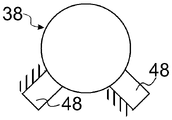
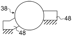
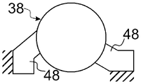
Fig. 4A-E respectively show schematic views of a portion of a nacelle according to an embodiment of the disclosure. For clarity, only the torque arm 48 and components of the drive train are shown. In the illustrated embodiment, the component of the drive train is a gearbox 38. As regards the remaining construction of the nacelle, reference may be made, for example, to the description above with respect to fig. 2.
A nacelle for a wind turbine according to the present disclosure includes a drive train with a drive train axis. The nacelle further comprises at least two torque arms positioned around the drive train axis. In the embodiment shown in fig. 4A-E, the nacelle comprises two torque arms 48. The torque arm 48 is attached to a component of the drive train, in particular to the gearbox 38. In general, the component of the drive train may be, for example, a gearbox or a generator. The torque arm may be fixedly attached to a component of the drive train.
The gearbox axis may coincide with the drive train axis. Specifically, the gearbox axis coincides with the axis of the input shaft of the gearbox. The input shaft is in particular a low speed shaft. More specifically, the low speed shaft is connected to the hub of the nacelle. In the exemplary embodiment shown in fig. 4A-E, the torque arm is oriented perpendicular to the drive train axis.
In the context of the present disclosure, the orientation of the torque arm is to be understood in particular as a direction parallel to a line connecting the drive train axis with a point of structural support of the torque arm (in particular an idealized point). The nacelle further comprises a frame attached to the yaw bearing. The torque arm 48 of the drive train is supported by the frame. In fig. 4A-D, the support areas are indicated by the shaded areas.
At least one of the torque arms has an orientation that at least substantially deviates from horizontal. An advantage of at least a significant deviation from the horizontal orientation is that the amount of space available alongside the drive train can be increased. In particular, the space available for e.g. walkways, exit routes or material handling may be larger. Additionally or alternatively, the nacelle may be configured to be smaller, in particular narrower, than a conventional nacelle. The nacelle according to the present disclosure may also have a reduced height compared to conventional nacelles.
The logistical requirements, in particular with regard to the transport of the nacelle, can be reduced. Furthermore, the workload with respect to field installation can be reduced. The material utilization efficiency can be improved. Furthermore, the size of the drive train itself, in particular the transport size, can be reduced. This may be particularly beneficial in case the drive train is to be transported separately from the nacelle.
As can be seen in the conventional design shown in fig. 3A-B, space alongside the drive train is blocked by the torque arm 48. In contrast, in a nacelle according to the present disclosure, such as shown in fig. 4A, the blockage of space beside the drive train by the torque arm 48 depicted by the left side is reduced or eliminated. The free space beside the drive train can be used for walkways, exit routes or material handling, for example. Thus, the width or height of the nacelle can potentially be reduced, as space above the drive train or beside the torque arm is not required for this purpose. In particular, the technician and the material may pass by the drive train or a component of the drive train, rather than over it. In this regard, the component of the drive train may be, for example, a gearbox support structure, or a generator.
In other words, the design of the torque arms is driven at least primarily by space requirements or load paths rather than symmetry considerations. In general, the loads that occur during operation of a wind turbine are not necessarily symmetrical. The corresponding loads on the torque arms are not necessarily equal. Specifically, the load from the torque may differ with respect to the rotational direction of the wind turbine.
In an embodiment, as shown for example in fig. 4A, two of the torque arms are at least significantly offset from being parallel to each other. The angle between the two torque arms may be less than 175 °, 160 ° or 145 °, for example.
In an embodiment, at least one of the torque arms has an orientation that is at least 10 ° off horizontal. The orientation may deviate from horizontal by an angle of at least 5 °, 15 °, or 25 °, for example. In the context of the present disclosure, an orientation at least significantly deviating from horizontal is understood to be an angle of at least 10 ° deviating from horizontal.
In an embodiment, as shown for example in fig. 4B, the two torque arms 48 may have an orientation that at least deviates significantly from horizontal. The space saving in the nacelle as described above can be further increased.
In embodiments, the shapes of the torque arms may differ from each other depending on the load. The shape of the torque arm may be based on the direction of rotation of the wind turbine in the operating state. Specifically, the shape of the torque arm may be selected in view of size and load requirements while ignoring symmetry considerations, at least in large part.
In an embodiment, the nacelle may comprise at least three torque arms. For example, the nacelle may include three, four, or five torque arms. In particular, the number of torque arms may be selected in view of size and load requirements while ignoring symmetry considerations, at least in large part.
In an embodiment, at least one of the torque arms is non-linear, as shown, for example, in fig. 4C-4D. Specifically, at least one of the torque arms includes a first section extending from the member in a first direction and a second section continuing from the first section in a second direction. In other words, at least one of the torque arms may, for example, have at least one kink or may be curved. The angle between the first direction and the second direction may be larger than, for example, 10 °, 15 ° or 20 °. Space utilization or load path distribution can be further optimized.
In an embodiment, at least one of the torque arms is supported from below by the frame, for example as shown in fig. 4A. The support from below is to be understood in particular in relation to the mounted state of the nacelle. In the installed state, the nacelle may be mounted on a tower, which extends from the support surface. More specifically, supporting from below is understood to be supporting the torque arm from the side facing the tower or the support surface. In fig. 4A, the torque arm 48 depicted on the right side is supported from below.
In an embodiment, at least one of the torque arms is supported by the frame from above. Supporting from above is understood to be supporting the torque arm from the side opposite to the side facing the tower or the support surface of the tower.
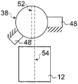
In an embodiment, at least one of the torque arms is supported in at least one of a lateral direction and a longitudinal direction relative to the driveline axis, as shown, for example, in fig. 4D-4E. In the embodiment shown in fig. 4D, the left depicted torque arm 48 is supported from a lateral direction with respect to the drive train axis. In the embodiment shown in fig. 4E, the two depicted torque arms 48 are supported from the longitudinal direction relative to the drive train axis. For example, support in the longitudinal direction may be provided via bolts inserted into holes indicated on the torque arm 48 depicted in fig. 4E.
FIG. 5 shows a schematic view of a portion of a nacelle according to an embodiment of the disclosure. Further, a section of the tower 12 of the wind turbine is shown including a yaw axis 54. In the illustrated embodiment, the nacelle central axis 52 intersects the drive train axis and extends parallel to the yaw axis 54.
In an embodiment, as shown in fig. 5, the nacelle is configured such that in the mounted state the distance between the drive train axis and the yaw axis 54 is larger than 1 cm. The distance between the drive train axis and the yaw axis may be greater than, for example, 1cm, 2cm, 4cm or 8 cm. Providing a distance between the drive train axis and the yaw axis may improve load distribution or space utilization in the nacelle.
In an embodiment, the main axis of the first torque arm 48 intersects the main axis of the second torque arm 48 at a point having a distance of more than 1cm, 2cm, 4cm or 8cm from the yaw axis 54.
FIG. 6 shows a flow chart of an embodiment of a method of supporting torque in a nacelle of a wind turbine according to the present disclosure. The method 100 of supporting a torque in a nacelle of a wind turbine having a drive train with a drive train axis begins at block 110. The method comprises the following steps: in block 120, at least two torque arms are provided that are positioned about a drive train axis and attached to a component of the drive train. The torque arm may be fixedly attached to a component of the drive train.
The method further comprises the following steps: in block 130, a frame attached to the yaw bearing is provided, wherein a torque arm of the drive train is supported by the frame. At least one of the torque arms has an orientation that at least substantially deviates from horizontal. The method ends in block 140.
This written description uses examples to disclose the invention, including the best mode, and also to enable any person skilled in the art to practice the invention, including making and using any devices or systems and performing any incorporated methods. The patentable scope of the invention is defined by the claims, and may include other examples that occur to those skilled in the art. Such other examples are intended to be within the scope of the claims if they include structural elements that do not differ from the literal language of the claims, or if they include equivalent structural elements with insubstantial differences from the literal languages of the claims.
The present disclosure may be additionally summarized by the following clauses.
Clause 1. a nacelle for a wind turbine, the nacelle comprising: a drive train with a drive train axis, at least two torque arms positioned around the drive train axis and attached to components of the drive train, and a frame attached to a yaw bearing, wherein the torque arms of the drive train are supported by the frame, and wherein at least one of the torque arms has an orientation that at least substantially deviates from horizontal.
Clause 2. the nacelle of clause 1, wherein at least one of the torque arms has an orientation that is at least 10 ° off horizontal.
Clause 3. the nacelle of any of the preceding clauses, wherein two of the torque arms are at least substantially offset from being parallel to each other.
Clause 4. the nacelle of any of the preceding clauses, wherein at least one of the torque arms is non-linear.
Clause 5. the nacelle of any of the preceding clauses, wherein at least one of the torque arms includes a first section extending from the member in a first direction and a second section continuing from the first section in a second direction, wherein an angle between the first direction and the second direction is greater than 10 °.
Clause 6. the nacelle of any of the preceding clauses, wherein at least one of the torque arms is supported from above by the frame.
Clause 8. the nacelle of any of the preceding clauses, configured such that, in an installed state, a distance between the drive train axis and the yaw axis is greater than 1 cm.
Clause 9. a method of supporting torque in a nacelle of a wind turbine having a drive train with a drive train axis, the method comprising: providing at least two torque arms positioned about the drive train axis and attached to a component of the drive train, and providing a frame attached to the yaw bearing, wherein the torque arms of the drive train are supported by the frame, and wherein at least one of the torque arms has an orientation that at least substantially deviates from horizontal.
Clause 11. the method of any of clauses 9-10, wherein two of the torque arms at least significantly diverge from being parallel to each other.
Clause 13. the method of any of clauses 9 to 12, wherein at least one of the torque arms is supported from below by the frame.
Clause 15. the method of any of clauses 9 to 14, wherein at least one of the torque arms is supported in at least one of a lateral direction and a longitudinal direction relative to the driveline axis.
Claims (10)
1. A nacelle for a wind turbine, the nacelle comprising:
a drive train with a drive train axis;
at least two torque arms positioned about the drive train axis and attached to components of the drive train; and
a frame attached to the yaw bearing, wherein
Torque arms of the drive train are supported by the frame, and wherein at least one of the torque arms has an orientation that at least substantially deviates from horizontal.
2. The nacelle of claim 1 wherein at least one of said torque arms has an orientation that is at least 10 ° out of horizontal.
3. The nacelle of any preceding claim, wherein two of the torque arms are at least substantially offset from being parallel to each other.
4. The nacelle of any of claims 1 or 2, wherein at least one of the torque arms is non-linear.
5. A nacelle according to any of claim 1 or claim 2, wherein at least one of the torque arms comprises a first section extending from the part in a first direction and a second section continuing from the first section in a second direction, wherein the angle between the first and second directions is larger than 10 °.
6. The nacelle of any of claims 1 or 2, wherein at least one of the torque arms is supported by the frame from above.
7. The nacelle of any of claims 1 or 2, wherein at least one of the torque arms is supported in at least one of a lateral direction and a longitudinal direction relative to the drive train axis.
8. Nacelle according to any of claims 1 or 2, configured such that in the mounted state the distance between the drive train axis and a yaw axis is larger than 1 cm.
9. A method of supporting torque in a nacelle of a wind turbine having a drive train with a drive train axis, the method comprising:
providing at least two torque arms positioned about the drive train axis and attached to a component of the drive train; and
providing a frame attached to a yaw bearing, wherein torque arms of the drive train are supported by the frame, and wherein at least one of the torque arms has an orientation that at least substantially deviates from horizontal.
10. The method of claim 9 wherein at least one of the torque arms has an orientation that is at least 10 ° off horizontal.
Applications Claiming Priority (2)
| Application Number | Priority Date | Filing Date | Title |
|---|---|---|---|
| EP20204397.2 | 2020-10-28 | ||
| EP20204397.2A EP3992452A1 (en) | 2020-10-28 | 2020-10-28 | A nacelle for a wind turbine |
Publications (1)
| Publication Number | Publication Date |
|---|---|
| CN114483487A true CN114483487A (en) | 2022-05-13 |
Family
ID=73037808
Family Applications (1)
| Application Number | Title | Priority Date | Filing Date |
|---|---|---|---|
| CN202111266846.6A Pending CN114483487A (en) | 2020-10-28 | 2021-10-28 | Nacelle for a wind turbine and method of supporting torque in such a nacelle |
Country Status (5)
| Country | Link |
|---|---|
| US (2) | US11608816B2 (en) |
| EP (1) | EP3992452A1 (en) |
| CN (1) | CN114483487A (en) |
| BR (1) | BR102021021116A2 (en) |
| CA (1) | CA3135062A1 (en) |
Family Cites Families (8)
| Publication number | Priority date | Publication date | Assignee | Title |
|---|---|---|---|---|
| US5810558A (en) * | 1996-01-16 | 1998-09-22 | Dresser-Rand Company | Bearing case support arrangement |
| ATE305101T1 (en) * | 2000-10-14 | 2005-10-15 | Franz Mitsch | GEARBOX MOUNTING FOR WIND TURBINE |
| DE102010044297B4 (en) * | 2010-09-03 | 2022-07-14 | Zf Friedrichshafen Ag | torque arm |
| EP2434154A1 (en) * | 2010-09-28 | 2012-03-28 | Siemens Aktiengesellschaft | Wind turbine active damping arrangement |
| EP2508754B1 (en) * | 2011-04-04 | 2016-03-30 | Siemens Aktiengesellschaft | Drive system for a wind turbine |
| CN108700023B (en) * | 2015-12-22 | 2020-12-01 | 维斯塔斯风力系统有限公司 | Bearing structure for multi-rotor wind turbine |
| US10495210B2 (en) * | 2017-11-09 | 2019-12-03 | General Electric Company | Integral ring gear and torque arm for a wind turbine gearbox |
| EP3715629A1 (en) * | 2019-03-27 | 2020-09-30 | General Electric Company | System and method for reducing the transport width of a gearbox for a wind turbine |
-
2020
- 2020-10-28 EP EP20204397.2A patent/EP3992452A1/en active Pending
-
2021
- 2021-10-20 CA CA3135062A patent/CA3135062A1/en active Pending
- 2021-10-21 BR BR102021021116-4A patent/BR102021021116A2/en unknown
- 2021-10-27 US US17/511,796 patent/US11608816B2/en active Active
- 2021-10-28 CN CN202111266846.6A patent/CN114483487A/en active Pending
-
2023
- 2023-03-20 US US18/186,385 patent/US20230228256A1/en active Pending
Also Published As
| Publication number | Publication date |
|---|---|
| EP3992452A1 (en) | 2022-05-04 |
| BR102021021116A2 (en) | 2022-05-10 |
| CA3135062A1 (en) | 2022-04-28 |
| US11608816B2 (en) | 2023-03-21 |
| US20230228256A1 (en) | 2023-07-20 |
| US20220128037A1 (en) | 2022-04-28 |
Similar Documents
| Publication | Publication Date | Title |
|---|---|---|
| US8011887B2 (en) | Rotor blade assembly | |
| EP2488748B1 (en) | Wind turbine | |
| EP1772623A1 (en) | Active flow control for wind turbine blades | |
| EP2505823A2 (en) | Transport frame for nacelle/rotor hub unit of a wind turbine, method of transporting and mounting a nacelle/rotor hub unit | |
| EP2893186B1 (en) | Vertical axis wind turbine | |
| US8858174B2 (en) | Wind turbine torque-speed control | |
| EP2395233B1 (en) | Configuration of a wind turbine nacelle for transportation | |
| US11867158B2 (en) | Back-up power supply for wind turbines | |
| US10823138B2 (en) | Counterweight assembly for use during single blade installation of a wind turbine | |
| EP3696403A1 (en) | System and method for protecting wind turbines from flutter during high wind speeds | |
| EP1668247B1 (en) | Bearing housing | |
| CN114483487A (en) | Nacelle for a wind turbine and method of supporting torque in such a nacelle | |
| US20220178391A1 (en) | System for a tower segment of a tower, a respective tower segment, and a wind turbine having a tower segment | |
| US11965479B2 (en) | System and method for repairing a gearbox of a wind turbine uptower | |
| JP2006077747A (en) | Multiple single-blade wind power generator | |
| US20230323860A1 (en) | Wind turbine frame with flexible coupling | |
| EP4144987B1 (en) | Nacelle cover panel | |
| CN218542476U (en) | Become oar device and wind generating set | |
| CN112020609A (en) | Method for retrofitting a wind turbine | |
| CN113982833A (en) | Wind power generation system | |
| EP4062056A1 (en) | Wind turbine operable in a reverse mode of operation and corresponding method of operating a wind turbine |
Legal Events
| Date | Code | Title | Description |
|---|---|---|---|
| PB01 | Publication | ||
| PB01 | Publication | ||
| SE01 | Entry into force of request for substantive examination | ||
| SE01 | Entry into force of request for substantive examination |