CN114473033A - Automatic cutting equipment for mechanical engineering - Google Patents
Automatic cutting equipment for mechanical engineering Download PDFInfo
- Publication number
- CN114473033A CN114473033A CN202210130104.9A CN202210130104A CN114473033A CN 114473033 A CN114473033 A CN 114473033A CN 202210130104 A CN202210130104 A CN 202210130104A CN 114473033 A CN114473033 A CN 114473033A
- Authority
- CN
- China
- Prior art keywords
- cutting
- motor
- mechanical engineering
- rod
- screw rod
- Prior art date
- Legal status (The legal status is an assumption and is not a legal conclusion. Google has not performed a legal analysis and makes no representation as to the accuracy of the status listed.)
- Pending
Links
Images


Classifications
-
- B—PERFORMING OPERATIONS; TRANSPORTING
- B23—MACHINE TOOLS; METAL-WORKING NOT OTHERWISE PROVIDED FOR
- B23D—PLANING; SLOTTING; SHEARING; BROACHING; SAWING; FILING; SCRAPING; LIKE OPERATIONS FOR WORKING METAL BY REMOVING MATERIAL, NOT OTHERWISE PROVIDED FOR
- B23D33/00—Accessories for shearing machines or shearing devices
- B23D33/02—Arrangements for holding, guiding, and/or feeding work during the operation
-
- B—PERFORMING OPERATIONS; TRANSPORTING
- B07—SEPARATING SOLIDS FROM SOLIDS; SORTING
- B07B—SEPARATING SOLIDS FROM SOLIDS BY SIEVING, SCREENING, SIFTING OR BY USING GAS CURRENTS; SEPARATING BY OTHER DRY METHODS APPLICABLE TO BULK MATERIAL, e.g. LOOSE ARTICLES FIT TO BE HANDLED LIKE BULK MATERIAL
- B07B1/00—Sieving, screening, sifting, or sorting solid materials using networks, gratings, grids, or the like
- B07B1/04—Stationary flat screens
-
- B—PERFORMING OPERATIONS; TRANSPORTING
- B23—MACHINE TOOLS; METAL-WORKING NOT OTHERWISE PROVIDED FOR
- B23D—PLANING; SLOTTING; SHEARING; BROACHING; SAWING; FILING; SCRAPING; LIKE OPERATIONS FOR WORKING METAL BY REMOVING MATERIAL, NOT OTHERWISE PROVIDED FOR
- B23D21/00—Machines or devices for shearing or cutting tubes
-
- B—PERFORMING OPERATIONS; TRANSPORTING
- B23—MACHINE TOOLS; METAL-WORKING NOT OTHERWISE PROVIDED FOR
- B23Q—DETAILS, COMPONENTS, OR ACCESSORIES FOR MACHINE TOOLS, e.g. ARRANGEMENTS FOR COPYING OR CONTROLLING; MACHINE TOOLS IN GENERAL CHARACTERISED BY THE CONSTRUCTION OF PARTICULAR DETAILS OR COMPONENTS; COMBINATIONS OR ASSOCIATIONS OF METAL-WORKING MACHINES, NOT DIRECTED TO A PARTICULAR RESULT
- B23Q1/00—Members which are comprised in the general build-up of a form of machine, particularly relatively large fixed members
- B23Q1/25—Movable or adjustable work or tool supports
- B23Q1/44—Movable or adjustable work or tool supports using particular mechanisms
-
- B—PERFORMING OPERATIONS; TRANSPORTING
- B23—MACHINE TOOLS; METAL-WORKING NOT OTHERWISE PROVIDED FOR
- B23Q—DETAILS, COMPONENTS, OR ACCESSORIES FOR MACHINE TOOLS, e.g. ARRANGEMENTS FOR COPYING OR CONTROLLING; MACHINE TOOLS IN GENERAL CHARACTERISED BY THE CONSTRUCTION OF PARTICULAR DETAILS OR COMPONENTS; COMBINATIONS OR ASSOCIATIONS OF METAL-WORKING MACHINES, NOT DIRECTED TO A PARTICULAR RESULT
- B23Q11/00—Accessories fitted to machine tools for keeping tools or parts of the machine in good working condition or for cooling work; Safety devices specially combined with or arranged in, or specially adapted for use in connection with, machine tools
- B23Q11/0042—Devices for removing chips
-
- B—PERFORMING OPERATIONS; TRANSPORTING
- B23—MACHINE TOOLS; METAL-WORKING NOT OTHERWISE PROVIDED FOR
- B23Q—DETAILS, COMPONENTS, OR ACCESSORIES FOR MACHINE TOOLS, e.g. ARRANGEMENTS FOR COPYING OR CONTROLLING; MACHINE TOOLS IN GENERAL CHARACTERISED BY THE CONSTRUCTION OF PARTICULAR DETAILS OR COMPONENTS; COMBINATIONS OR ASSOCIATIONS OF METAL-WORKING MACHINES, NOT DIRECTED TO A PARTICULAR RESULT
- B23Q5/00—Driving or feeding mechanisms; Control arrangements therefor
- B23Q5/02—Driving main working members
- B23Q5/04—Driving main working members rotary shafts, e.g. working-spindles
- B23Q5/10—Driving main working members rotary shafts, e.g. working-spindles driven essentially by electrical means
-
- B—PERFORMING OPERATIONS; TRANSPORTING
- B23—MACHINE TOOLS; METAL-WORKING NOT OTHERWISE PROVIDED FOR
- B23Q—DETAILS, COMPONENTS, OR ACCESSORIES FOR MACHINE TOOLS, e.g. ARRANGEMENTS FOR COPYING OR CONTROLLING; MACHINE TOOLS IN GENERAL CHARACTERISED BY THE CONSTRUCTION OF PARTICULAR DETAILS OR COMPONENTS; COMBINATIONS OR ASSOCIATIONS OF METAL-WORKING MACHINES, NOT DIRECTED TO A PARTICULAR RESULT
- B23Q5/00—Driving or feeding mechanisms; Control arrangements therefor
- B23Q5/22—Feeding members carrying tools or work
- B23Q5/26—Fluid-pressure drives
-
- B—PERFORMING OPERATIONS; TRANSPORTING
- B23—MACHINE TOOLS; METAL-WORKING NOT OTHERWISE PROVIDED FOR
- B23Q—DETAILS, COMPONENTS, OR ACCESSORIES FOR MACHINE TOOLS, e.g. ARRANGEMENTS FOR COPYING OR CONTROLLING; MACHINE TOOLS IN GENERAL CHARACTERISED BY THE CONSTRUCTION OF PARTICULAR DETAILS OR COMPONENTS; COMBINATIONS OR ASSOCIATIONS OF METAL-WORKING MACHINES, NOT DIRECTED TO A PARTICULAR RESULT
- B23Q7/00—Arrangements for handling work specially combined with or arranged in, or specially adapted for use in connection with, machine tools, e.g. for conveying, loading, positioning, discharging, sorting
- B23Q7/003—Cyclically moving conveyors
Abstract
The invention belongs to the technical field of cutting equipment, and discloses automatic cutting equipment for mechanical engineering, which comprises a machine base, a screw rod, a hydraulic driving rod, a cutting motor, a clamping and pressing plate, a cutting workbench, a conveying belt and a fine scrap collecting tank, wherein the machine base is provided with a guide rail; a cutting workbench is supported and mounted above the machine base through a machine column, an organic transverse frame is fixedly mounted on the top end of the machine column, and a fine scrap collecting tank and a coarse scrap collecting tank are arranged below the cutting workbench through a supporting plate; a screw rod is arranged in the transverse frame, and a screw rod motor which is in driving connection with the screw rod is arranged at one end of the transverse frame; the hydraulic driving rod is arranged on the screw rod through a screw rod sliding seat, and the bottom end of the hydraulic driving rod is provided with a cutting motor through a motor mounting seat. According to the automatic cutting machine, a transmission belt transmits a to-be-cut accessory, the accessory is clamped and fixed by the pressing plate, the electric cabinet orderly controls the cutting height and position to be adjusted, automatic cutting is achieved, and the cutting quality is improved; the labor intensity of workers is reduced, the working environment is improved, and the effect of effectively collecting and cleaning the scraps is achieved.
Description
Technical Field
The invention relates to the technical field of cutting equipment, in particular to automatic cutting equipment for mechanical engineering.
Background
Mechanical engineering is an engineering discipline relating to the analysis, design, manufacture and maintenance of mechanical systems using the laws of physics. Cutting is a physical action. The narrow sense of cutting is to cut an object (e.g., an object having low hardness such as food and wood) with a sharp tool such as a knife: cutting in the broad sense means breaking an object under pressure or high temperature by means of a tool, such as a machine tool, a flame, etc. The cutting has important function in production and life of people.
The general cutting device has the problem that the cutting depth is not easy to adjust, the automatic driving cannot be carried out to cut articles when the automatic cutting device is used, and meanwhile, scraps after cutting are not easy to treat.
The cutting is a physical action, the narrow cutting means cutting an object (such as food, wood and other objects with low hardness) by using a sharp tool such as a knife, the broad cutting means cutting the object by using a tool such as a machine tool, flame and the like, so that the object is broken under the action of pressure or high temperature, along with the development of the modern machining industry, the requirements on the cutting quality and precision are continuously improved, and the requirements on the improvement of the production efficiency, the reduction of the production cost and the high-intelligence automatic cutting function are also improved. In the traditional cutting mode, a cutting piece is fixed on a clamp, and then the cutting piece is cut by manually operating a cutting machine, so that the labor amount of workers is increased, the cutting precision is deviated, and the cutting efficiency is reduced; the steel pipe is a steel material with a hollow section, the length of the steel pipe is far greater than the diameter or the perimeter, the steel pipe can be used for conveying fluid and powdery solids, exchanging heat energy, manufacturing mechanical parts and containers, and can also be used for manufacturing building structure net racks, pillars and mechanical supports, the weight of the device can be further reduced, the steel pipe is widely applied in production and life, and when the steel pipe is actually used, the steel pipe needs to be cut firstly; in addition, the traditional cutting mode can not collect and clean the scraps generated by cutting, so that the scraps are scattered, the working environment of workers is deteriorated, and the physical health of the workers is influenced. Therefore, an automatic cutting device for mechanical engineering is provided.
Disclosure of Invention
The invention mainly aims to provide automatic cutting equipment for mechanical engineering; when the workpiece is conveyed to the position below the clamping and pressing plate, the electric telescopic rod is started to drive the clamping and pressing plate to move downwards to clamp, press and fix the workpiece to be cut; the stability of the automatic cutting device for the mechanical engineering can be ensured, the problem that the cutting size is inconsistent with the requirement due to the position of the article during cutting is avoided, and the practicability of the automatic cutting device for the mechanical engineering is greatly improved; the labor intensity of workers can be further reduced; cutting chips with different sizes respectively fall into a fine chip collecting tank and a coarse chip collecting tank for collection; the cutting scraps generated after cutting can be conveniently stored; the scrap generated by cutting can be effectively collected and cleaned, the working environment of workers is improved, the physical health of the workers is facilitated, and the effect of effectively collecting and cleaning the scrap is achieved; highly adjusting the cutting motor through the orderly hydraulic drive pole of electric cabinet, the orderly control lead screw motor of accessible electric cabinet, and then adjusting cutting position, the orderly control cutting motor of accessible electric cabinet, and then treat the cutting accessory and cut, reached the effect of automatic cutting.
In order to achieve the purpose, the automatic cutting equipment for mechanical engineering provided by the invention comprises a machine base, a machine column, a machine cross frame, a screw rod, a hydraulic driving rod, a cutting motor, an electric telescopic rod, a clamping and pressing plate, a cutting workbench, a conveying belt, a supporting plate, a filtering metal net, a fine scrap collecting tank and a coarse scrap collecting tank; a cutting workbench is supported and mounted above the machine base through a machine column, an organic transverse frame is fixedly mounted on the top end of the machine column, and a fine scrap collecting tank and a coarse scrap collecting tank are arranged below the cutting workbench through a supporting plate; a screw rod is arranged in the transverse frame, and a screw rod motor which is in driving connection with the screw rod is arranged at one end of the transverse frame; the hydraulic driving rod is arranged on the screw rod through a screw rod sliding seat, and the bottom end of the hydraulic driving rod is provided with a cutting motor through a motor mounting seat; a fixed plate is installed on the machine column through a fixed installation sleeve, an electric telescopic rod is installed at the bottom of the end head of the fixed plate, and a clamping pressing plate is installed at the telescopic end of the bottom of the electric telescopic rod; the front end and the rear end of the cutting workbench are provided with transmission belts through driving rollers.
Optionally, a support column is installed at the bottom of the base, and a movable caster is installed at the bottom of the support column.
Optionally, two ends of the screw rod are mounted inside the cross frame through a screw rod base.
Optionally, the cutting motor is a bidirectional coaxial motor, and the two ends of the cutting motor are detachably and drivingly provided with a small cutting blade and a large cutting blade.
Optionally, a planar clamping panel and an arc-shaped clamping groove are arranged at the bottom of the clamping and pressing plate; the clamping pressing plate is driven by the electric telescopic rod to move up and down.
Optionally, an electric cabinet is further installed on the machine base; the electric cabinet is provided with a control switch panel used for controlling the screw rod motor, the cutting motor and the electric telescopic rod.
Optionally, the cutting motor is driven by a hydraulic drive rod to move up and down, and the hydraulic drive rod is driven by a screw rod motor to move on the screw rod in the horizontal direction through a screw rod sliding seat.
Optionally, the middle part of the cutting workbench is provided with a cutting through groove, the cutting through groove is arranged right above the fine scrap collecting groove, a filtering metal net is arranged above the fine scrap collecting groove, the filtering metal net is in a triangular design, and two sides of the filtering metal net are communicated with the coarse scrap collecting groove through a feed opening.
Optionally, the electric telescopic rod adopts an NH32-900 electric push rod.
Optionally, a fitting to be cut is arranged on the cutting workbench in a pressing mode through the clamping pressing plate.
According to the technical scheme, when the accessory to be cut is placed on the transmission belt above the cutting workbench of the device, the driving roller is started to drive the transmission belt to transmit the accessory to be cut, and when the accessory to be cut is transmitted to the position below the clamping and pressing plate, the electric telescopic rod is started to drive the clamping and pressing plate to move downwards to clamp, press and fix the accessory to be cut; the stability of the automatic cutting device for the mechanical engineering can be ensured, the problem that the cutting size is inconsistent with the requirement due to the position of the article during cutting is avoided, and the practicability of the automatic cutting device for the mechanical engineering is greatly improved; the labor intensity of workers can be further reduced, the cutting machine is convenient to use, the lead screw motor drives the lead screw to drive the cutting motor to move in the horizontal direction through the lead screw sliding seat, the cutting motor is positioned right above a to-be-cut accessory, and a small cutting blade or a large cutting blade is arranged on a driving shaft of the cutting motor according to the requirements of cutting depth and the like; the large cutting blade can cut the periphery of the pipe at a constant speed, so that the flatness of the cut surface of the steel pipe can be further improved, the cutting quality of the steel pipe can be further improved, and the large cutting blade is suitable for popularization and use; debris generated in the cutting process can fall through the cutting through groove in the middle of the cutting workbench, is filtered by the filtering metal net above the interior of the fine scrap collecting tank, and the cutting scraps with different sizes respectively fall into the fine scrap collecting tank and the coarse scrap collecting tank to be collected; the cutting scraps generated after cutting can be conveniently stored; the scrap generated by cutting can be effectively collected and cleaned, the working environment of workers is improved, the physical health of the workers is facilitated, and the effect of effectively collecting and cleaning the scrap is achieved;
after the cutting, the clamping and pressing plate is lifted up to continue to transport the cut fitting out through the conveyor belt.
The orderly hydraulic drive pole of accessible electric cabinet highly adjusts cutting motor, and the orderly control lead screw motor of accessible electric cabinet, and then adjusts cutting position, and the orderly control cutting motor of accessible electric cabinet, and then treat the cutting accessory and cut, reached the effect of automatic cutting.
Drawings
In order to more clearly illustrate the embodiments of the present invention or the technical solutions in the prior art, the drawings used in the description of the embodiments or the prior art will be briefly described below, it is obvious that the drawings in the following description are only some embodiments of the present invention, and for those skilled in the art, other drawings can be obtained according to the structures shown in the drawings without creative efforts.
FIG. 1 is a schematic structural diagram of an automatic cutting apparatus for mechanical engineering according to the present invention;
FIG. 2 is a schematic structural diagram of an embodiment of an automatic cutting apparatus for mechanical engineering according to the present invention;
FIG. 3 is a schematic structural diagram of an embodiment of an automatic cutting apparatus for mechanical engineering according to the present invention;
FIG. 4 is a schematic top view of a cutting table and a conveyor belt of an automatic cutting apparatus for mechanical engineering according to the present invention;
FIG. 5 is a schematic top view of the connection between the clamping and pressing plate and the cutting table of the automatic cutting apparatus for mechanical engineering according to the present invention;
FIG. 6 is a schematic structural diagram of a clamping and pressing plate of an automatic cutting apparatus for mechanical engineering according to the present invention;
FIG. 7 is a schematic structural diagram of a clamping and pressing plate in an automatic cutting apparatus for mechanical engineering according to the present invention;
the reference numbers illustrate:
1. a machine base; 2. a column; 3. a cross frame; 4. a screw rod; 5. a screw motor; 6. a hydraulic drive rod; 7. cutting the motor; 8. a small cutting blade; 9. an electric telescopic rod; 10. clamping the pressing plate; 11. cutting the working table; 12. a conveyor belt; 13. a support plate; 14. filtering the metal net; 15. cutting a through groove; 16. a fines collection tank; 17. a coarse scrap collecting tank; 18. a feeding port; 19. a drive roller; 20. a fitting to be cut; 21. fixing the mounting sleeve; 22. a fixing plate; 23. an electric cabinet; 24. moving the caster; 41. a lead screw slide seat; 101. a planar clamping panel; 102. an arc-shaped clamping groove.
The implementation, functional features and advantages of the objects of the present invention will be further explained with reference to the accompanying drawings.
Detailed Description
The technical solutions in the embodiments of the present invention will be clearly and completely described below with reference to the drawings in the embodiments of the present invention, and it is obvious that the described embodiments are only a part of the embodiments of the present invention, and not all of the embodiments. All other embodiments, which can be derived by a person skilled in the art from the embodiments given herein without making any creative effort, shall fall within the protection scope of the present invention.
It should be noted that, if directional indications (such as up, down, left, right, front, and back … …) are involved in the embodiment of the present invention, the directional indications are only used for explaining the relative position relationship between the components, the motion situation, and the like under a certain posture (as shown in the drawing), and if the certain posture is changed, the directional indications are changed accordingly.
In addition, if there is a description of "first", "second", etc. in an embodiment of the present invention, the description of "first", "second", etc. is for descriptive purposes only and is not to be construed as indicating or implying relative importance or implicitly indicating the number of technical features indicated. Thus, a feature defined as "first" or "second" may explicitly or implicitly include at least one such feature. In addition, technical solutions between various embodiments may be combined with each other, but must be realized by a person skilled in the art, and when the technical solutions are contradictory or cannot be realized, such a combination should not be considered to exist, and is not within the protection scope of the present invention.
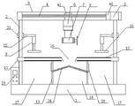
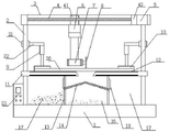
As shown in fig. 1 to 7, the present invention provides an automatic cutting device for mechanical engineering, which includes a machine base 1, a machine column 2, a machine cross frame 3, a screw rod 4, a hydraulic drive rod 6, a cutting motor 7, an electric telescopic rod 9, a clamping and pressing plate 10, a cutting workbench 11, a transmission belt 12, a support plate 13, a filtering metal net 14, a fine scrap collecting tank 16 and a coarse scrap collecting tank 17; a cutting workbench 11 is supported and installed above the machine base 1 through a machine column 2, an organic transverse frame 3 is fixedly installed on the top end of the machine column 2, and a fine scrap collecting tank 16 and a coarse scrap collecting tank 17 are arranged below the cutting workbench 11 through a supporting plate 13; a screw rod 4 is arranged in the transverse frame 3, and a screw rod motor 5 which is in driving connection with the screw rod 4 is arranged at one end of the transverse frame 3; the hydraulic driving rod 6 is arranged on the screw rod 4 through a screw rod sliding seat 41, and the bottom end of the hydraulic driving rod 6 is provided with a cutting motor 7 through a motor mounting seat; a fixed plate 22 is arranged on the machine column 2 through a fixed mounting sleeve 21, an electric telescopic rod 9 is arranged at the bottom of the end head of the fixed plate 22, and a clamping and pressing plate 10 is arranged at the telescopic end of the bottom of the electric telescopic rod 9; a conveyor belt 12 is installed on the front and rear ends of the cutting table 11 by a driving roller 19.
It is noted that the bottom of the machine base 1 is provided with a support column, and the bottom of the support column is provided with a movable caster 24.
It is noted that both ends of the screw 4 are mounted inside the cross frame 3 through screw seats.
It is worth noting that the cutting motor 7 adopts a bidirectional coaxial motor, and the two ends of the cutting motor 7 are detachably and drivingly provided with a small cutting blade 8 and a large cutting blade.
It is worth noting that the bottom of the clamping and pressing plate 10 is provided with a plane clamping panel 101 and an arc-shaped clamping groove 102; the clamping and pressing plate 10 is driven by the electric telescopic rod 9 to move up and down; the planar accessory to be cut and the cylindrical accessory to be cut can be clamped, pressed and fixed through the planar clamping panel 101 and the arc-shaped clamping groove 102, and the cutting requirements of engineering accessories of different machine types are met.
It is worth noting that an electric cabinet 23 is also installed on the stand 1; the electric cabinet 23 is provided with a control switch panel for controlling the screw motor 5, the cutting motor 7 and the electric telescopic rod 9.
It is noted that the cutting motor 7 is driven by a hydraulic drive rod 6 to move up and down, and the hydraulic drive rod 6 is driven by a screw motor 5 to move horizontally on the screw 4 through a screw slide 41.
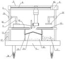
It is worth noting that the middle of the cutting workbench 11 is provided with a cutting through groove 15, the cutting through groove 15 is arranged right above the fine scrap collecting groove 16, a filtering metal net 14 is arranged above the fine scrap collecting groove 16, the filtering metal net 14 is in a triangular design, and two sides of the filtering metal net are communicated with the coarse scrap collecting groove 17 through a feed opening 18.
It is noted that the electric telescopic rod 9 adopts an NH32-900 electric push rod.
It is to be noted that the cutting table 11 is provided with a fitting 20 to be cut pressed thereon by the clamping and pressing plate 10.
The working principle and the using process of the invention are as follows: when the device is used, when a mechanical cutting worker puts a to-be-cut accessory 20 on a transmission belt 12 above a cutting workbench 11 of the device, a driving roller 19 is started to drive the transmission belt 12 to transmit the to-be-cut accessory 20, and when the to-be-cut accessory is transmitted below a clamping and pressing plate 10, an electric telescopic rod 9 is started to drive the clamping and pressing plate 10 to move downwards to clamp, press and fix the to-be-cut accessory 20; the stability of the automatic cutting device for the mechanical engineering can be ensured, the problem that the cutting size is inconsistent with the requirement due to the position of the article during cutting is avoided, and the practicability of the automatic cutting device for the mechanical engineering is greatly improved; the labor intensity of workers can be further reduced, the use is convenient, then the lead screw 4 is driven by the lead screw motor 5 to drive the cutting motor 7 to move in the horizontal direction through the lead screw slide seat 41, so that the cutting motor 7 is positioned right above the accessory 20 to be cut, and a small cutting blade 8 or a large cutting blade is arranged on a driving shaft of the cutting motor 7 according to the requirements of cutting depth and the like; the large cutting blade can cut the periphery of the pipe at a constant speed, so that the flatness of the cut surface of the steel pipe can be further improved, the cutting quality of the steel pipe can be further improved, and the large cutting blade is suitable for popularization and use; debris generated in the cutting process can fall through the cutting through groove 15 in the middle of the cutting workbench 11, is filtered through the filtering metal net 14 above the interior of the fine debris collecting groove 16, and the cutting debris with different sizes respectively fall into the fine debris collecting groove 16 and the coarse debris collecting groove 17 to be collected; the cutting scraps generated after cutting can be conveniently stored; the scrap generated by cutting can be effectively collected and cleaned, the working environment of workers is improved, the physical health of the workers is facilitated, and the effect of effectively collecting and cleaning the scrap is achieved;
after cutting, the clamping and pressing plate 10 is lifted and transported further by the conveyor belt 12 to the cut fitting.
Accessible electric cabinet 23 is orderly hydraulic drive pole 6 highly adjusts cutting motor 7, and the orderly control lead screw motor 5 of accessible electric cabinet 23, and then adjusts the cutting position, and the orderly control cutting motor 7 of accessible electric cabinet 23, and then treats cutting accessory 20 and cut, has reached the effect of automatic cutting.
The above description is only a preferred embodiment of the present invention, and is not intended to limit the scope of the present invention, and all modifications and equivalents of the present invention, which are made by the contents of the present specification and the accompanying drawings, or directly/indirectly applied to other related technical fields, are included in the scope of the present invention.
Claims (10)
1. The automatic cutting equipment for mechanical engineering is characterized by comprising a machine base (1), a machine column (2), a machine cross frame (3), a screw rod (4), a hydraulic driving rod (6), a cutting motor (7), an electric telescopic rod (9), a clamping and pressing plate (10), a cutting workbench (11), a conveying belt (12), a supporting plate (13), a filtering metal net (14), a fine scrap collecting tank (16) and a coarse scrap collecting tank (17); a cutting workbench (11) is supported and installed above the machine base (1) through a machine column (2), an organic transverse frame (3) is fixedly installed on the top end of the machine column (2), and a fine scrap collecting tank (16) and a coarse scrap collecting tank (17) are arranged below the cutting workbench (11) through a supporting plate (13); a screw rod (4) is arranged in the transverse frame (3), and a screw rod motor (5) which is in driving connection with the screw rod (4) is arranged at one end of the transverse frame (3); the hydraulic drive rod (6) is arranged on the screw rod (4) through a screw rod sliding seat (41), and the bottom end of the hydraulic drive rod (6) is provided with a cutting motor (7) through a motor mounting seat; a fixed plate (22) is installed on the machine column (2) through a fixed installation sleeve (21), an electric telescopic rod (9) is installed at the bottom of the end head of the fixed plate (22), and a clamping pressing plate (10) is installed at the telescopic end of the bottom of the electric telescopic rod (9); the front end and the rear end of the cutting workbench (11) are provided with a transmission belt (12) through a driving roller (19).
2. The automatic cutting equipment for mechanical engineering according to claim 1, characterized in that the base (1) is provided at its bottom with a support column, and the support column is provided at its bottom with a caster (24).
3. The automatic cutting apparatus for mechanical engineering according to claim 1, wherein both ends of the screw (4) are installed inside the traverse frame (3) through screw seats.
4. The automatic cutting equipment for mechanical engineering, as set forth in claim 1, characterized in that the cutting motor (7) is a bidirectional coaxial motor, and both ends of the cutting motor (7) are detachably driveably equipped with a small cutting blade (8) and a large cutting blade.
5. The automatic cutting equipment for mechanical engineering according to claim 1, wherein the bottom of the clamping and pressing plate (10) is provided with a plane clamping panel (101) and an arc-shaped clamping groove (102); the clamping and pressing plate (10) is driven by the electric telescopic rod (9) to move up and down.
6. The automatic cutting equipment for mechanical engineering according to claim 1, characterized in that an electric cabinet (23) is further mounted on said machine base (1); the electric cabinet (23) is provided with a control switch panel for controlling the screw rod motor (5), the cutting motor (7) and the electric telescopic rod (9).
7. The automatic cutting equipment for mechanical engineering according to claim 1, characterized in that the cutting motor (7) is driven by a hydraulic driving rod (6) to move up and down, and the hydraulic driving rod (6) is driven by a lead screw motor (5) to move horizontally on the lead screw (4) through a lead screw slide (41).
8. The automatic cutting equipment for mechanical engineering according to claim 1, characterized in that the cutting table (11) is provided with a cutting through slot (15) in the middle, the cutting through slot (15) is arranged directly above the fine dust collecting tank (16), a filtering metal net (14) is arranged above the interior of the fine dust collecting tank (16), the filtering metal net (14) is in a triangular design, and the two sides are communicated with the coarse dust collecting tank (17) through a feed opening (18).
9. The automatic cutting equipment for mechanical engineering according to claim 1, characterized in that the electric telescopic rod (9) uses an NH32-900 electric push rod.
10. The automatic cutting equipment for mechanical engineering according to claim 1, characterized in that the cutting table (11) is provided with a fitting (20) to be cut pressed thereon by means of a clamping and pressing plate (10).
Priority Applications (1)
| Application Number | Priority Date | Filing Date | Title |
|---|---|---|---|
| CN202210130104.9A CN114473033A (en) | 2022-02-11 | 2022-02-11 | Automatic cutting equipment for mechanical engineering |
Applications Claiming Priority (1)
| Application Number | Priority Date | Filing Date | Title |
|---|---|---|---|
| CN202210130104.9A CN114473033A (en) | 2022-02-11 | 2022-02-11 | Automatic cutting equipment for mechanical engineering |
Publications (1)
| Publication Number | Publication Date |
|---|---|
| CN114473033A true CN114473033A (en) | 2022-05-13 |
Family
ID=81479710
Family Applications (1)
| Application Number | Title | Priority Date | Filing Date |
|---|---|---|---|
| CN202210130104.9A Pending CN114473033A (en) | 2022-02-11 | 2022-02-11 | Automatic cutting equipment for mechanical engineering |
Country Status (1)
| Country | Link |
|---|---|
| CN (1) | CN114473033A (en) |
Cited By (1)
| Publication number | Priority date | Publication date | Assignee | Title |
|---|---|---|---|---|
| CN114713904A (en) * | 2022-06-08 | 2022-07-08 | 奥王建筑材料科技有限公司 | Dustless cutting device of architectural shape |
Citations (12)
| Publication number | Priority date | Publication date | Assignee | Title |
|---|---|---|---|---|
| CN206763317U (en) * | 2017-02-16 | 2017-12-19 | 重庆市赛特刚玉有限公司 | Differential processing unit (plant) |
| CN208945270U (en) * | 2018-11-15 | 2019-06-07 | 临沂大学 | A kind of mechanical engineering autoamtic cutter |
| CN110280842A (en) * | 2019-08-06 | 2019-09-27 | 湖北实美科技有限公司 | A kind of aluminium section bar cutter device with collection scrap function |
| CN209633467U (en) * | 2018-08-22 | 2019-11-15 | 醴陵市永诚电瓷电器有限公司 | A kind of cutting equipment of bushing insulator |
| CN209969925U (en) * | 2019-05-29 | 2020-01-21 | 成都磐龙机械设备有限公司 | Environment-friendly cutting machine |
| CN110813688A (en) * | 2019-11-27 | 2020-02-21 | 徐州佳禾农业科技有限公司 | Seed production is with classified screening device |
| CN210207530U (en) * | 2019-07-01 | 2020-03-31 | 江西新凤微晶玉石有限公司 | Jade processing filter equipment |
| CN112604931A (en) * | 2020-11-19 | 2021-04-06 | 凤台县天宝建材有限责任公司 | Waste residue recycle device for extracting scandium from coal gangue |
| CN212925532U (en) * | 2020-03-17 | 2021-04-09 | 舒城浩缘朋纺织品有限公司 | Cutting and fixing device for clothing sample wafer |
| CN213316018U (en) * | 2020-08-03 | 2021-06-01 | 江苏力沃新能源科技股份有限公司 | Flux recovery device |
| CN213568517U (en) * | 2020-09-25 | 2021-06-29 | 安徽省恒金矿业有限公司 | Transfer device for limestone production |
| CN215202424U (en) * | 2021-04-19 | 2021-12-17 | 江西雄通木业有限公司 | Dust filtration formula wood working equipment |
-
2022
- 2022-02-11 CN CN202210130104.9A patent/CN114473033A/en active Pending
Patent Citations (12)
| Publication number | Priority date | Publication date | Assignee | Title |
|---|---|---|---|---|
| CN206763317U (en) * | 2017-02-16 | 2017-12-19 | 重庆市赛特刚玉有限公司 | Differential processing unit (plant) |
| CN209633467U (en) * | 2018-08-22 | 2019-11-15 | 醴陵市永诚电瓷电器有限公司 | A kind of cutting equipment of bushing insulator |
| CN208945270U (en) * | 2018-11-15 | 2019-06-07 | 临沂大学 | A kind of mechanical engineering autoamtic cutter |
| CN209969925U (en) * | 2019-05-29 | 2020-01-21 | 成都磐龙机械设备有限公司 | Environment-friendly cutting machine |
| CN210207530U (en) * | 2019-07-01 | 2020-03-31 | 江西新凤微晶玉石有限公司 | Jade processing filter equipment |
| CN110280842A (en) * | 2019-08-06 | 2019-09-27 | 湖北实美科技有限公司 | A kind of aluminium section bar cutter device with collection scrap function |
| CN110813688A (en) * | 2019-11-27 | 2020-02-21 | 徐州佳禾农业科技有限公司 | Seed production is with classified screening device |
| CN212925532U (en) * | 2020-03-17 | 2021-04-09 | 舒城浩缘朋纺织品有限公司 | Cutting and fixing device for clothing sample wafer |
| CN213316018U (en) * | 2020-08-03 | 2021-06-01 | 江苏力沃新能源科技股份有限公司 | Flux recovery device |
| CN213568517U (en) * | 2020-09-25 | 2021-06-29 | 安徽省恒金矿业有限公司 | Transfer device for limestone production |
| CN112604931A (en) * | 2020-11-19 | 2021-04-06 | 凤台县天宝建材有限责任公司 | Waste residue recycle device for extracting scandium from coal gangue |
| CN215202424U (en) * | 2021-04-19 | 2021-12-17 | 江西雄通木业有限公司 | Dust filtration formula wood working equipment |
Cited By (1)
| Publication number | Priority date | Publication date | Assignee | Title |
|---|---|---|---|---|
| CN114713904A (en) * | 2022-06-08 | 2022-07-08 | 奥王建筑材料科技有限公司 | Dustless cutting device of architectural shape |
Similar Documents
| Publication | Publication Date | Title |
|---|---|---|
| CN110369606B (en) | Automatic punching machine for hardware pipes | |
| CN104526494B (en) | A kind of Slabstone edge polisher | |
| CN207479719U (en) | A kind of Novel plate shearing machine | |
| CN208214795U (en) | A kind of digital controlled rotary plate shearing machine and the production system with the plate shearing machine | |
| CN108500361A (en) | A kind of cutter device for hardware plank | |
| CN210333881U (en) | Punching machine | |
| KR20150084357A (en) | Automatic two-sided material supply top grinder | |
| CN111014815A (en) | Double-end angle section bar cutting equipment | |
| CN114473033A (en) | Automatic cutting equipment for mechanical engineering | |
| CN211661225U (en) | Double-end angle section bar cutting equipment | |
| CN211438340U (en) | Plate shearing machine | |
| CN211728445U (en) | Vertical double-head processing machine tool | |
| CN211282706U (en) | Adjustable cylinder class material loading machine conveying mechanism | |
| CN211311310U (en) | Multi-shaft glass cutting equipment | |
| CN113338021B (en) | Automatic double-station beveling device for non-woven fabric | |
| CN215920075U (en) | Abrasive wheel cutting machine with eyeshield structure | |
| CN215033981U (en) | Sheet metal cutting device | |
| CN217799666U (en) | Special-shaped pipe fitting laser cutting equipment | |
| CN215200776U (en) | Condenser pipe processing location structure | |
| CN219852369U (en) | Cutting equipment of tee bend pipe fitting | |
| CN217551915U (en) | Cutting device is used in aluminum product processing | |
| CN218109556U (en) | Numerical control sawing machine | |
| CN219567804U (en) | Glass plate cutting table | |
| CN210387815U (en) | Linear groove grooving machine for long-strip-shaped rod body | |
| CN217750385U (en) | Automatic grooving device for surface processing of sectional material |
Legal Events
| Date | Code | Title | Description |
|---|---|---|---|
| PB01 | Publication | ||
| PB01 | Publication | ||
| SE01 | Entry into force of request for substantive examination | ||
| SE01 | Entry into force of request for substantive examination |