CN114472315A - Water-saving walnut green shell recycling device - Google Patents
Water-saving walnut green shell recycling device Download PDFInfo
- Publication number
- CN114472315A CN114472315A CN202210084303.0A CN202210084303A CN114472315A CN 114472315 A CN114472315 A CN 114472315A CN 202210084303 A CN202210084303 A CN 202210084303A CN 114472315 A CN114472315 A CN 114472315A
- Authority
- CN
- China
- Prior art keywords
- water
- walnut
- block
- plate
- pool
- Prior art date
- Legal status (The legal status is an assumption and is not a legal conclusion. Google has not performed a legal analysis and makes no representation as to the accuracy of the status listed.)
- Granted
Links
- 235000009496 Juglans regia Nutrition 0.000 title claims abstract description 73
- 235000020234 walnut Nutrition 0.000 title claims abstract description 73
- 238000004064 recycling Methods 0.000 title claims abstract description 18
- 240000007049 Juglans regia Species 0.000 title 1
- XLYOFNOQVPJJNP-UHFFFAOYSA-N water Substances O XLYOFNOQVPJJNP-UHFFFAOYSA-N 0.000 claims abstract description 110
- 238000004140 cleaning Methods 0.000 claims abstract description 77
- 241000758789 Juglans Species 0.000 claims abstract description 72
- 239000002893 slag Substances 0.000 claims abstract description 30
- 239000007921 spray Substances 0.000 claims abstract description 24
- 238000003860 storage Methods 0.000 claims abstract description 10
- 230000007246 mechanism Effects 0.000 claims description 66
- 238000001914 filtration Methods 0.000 claims description 37
- 238000005273 aeration Methods 0.000 claims description 11
- 238000005507 spraying Methods 0.000 claims description 9
- 239000000463 material Substances 0.000 claims description 8
- 230000002146 bilateral effect Effects 0.000 claims 1
- 239000010903 husk Substances 0.000 abstract description 12
- 230000000694 effects Effects 0.000 abstract description 10
- 125000004122 cyclic group Chemical group 0.000 abstract description 3
- 239000010865 sewage Substances 0.000 description 10
- 230000005484 gravity Effects 0.000 description 6
- 230000009471 action Effects 0.000 description 5
- 238000001125 extrusion Methods 0.000 description 5
- 238000000746 purification Methods 0.000 description 5
- 239000002351 wastewater Substances 0.000 description 5
- 238000007599 discharging Methods 0.000 description 4
- 238000000034 method Methods 0.000 description 3
- 239000012141 concentrate Substances 0.000 description 2
- 239000012535 impurity Substances 0.000 description 2
- 238000003825 pressing Methods 0.000 description 2
- 230000008569 process Effects 0.000 description 2
- 239000008213 purified water Substances 0.000 description 2
- 238000003756 stirring Methods 0.000 description 2
- 230000000903 blocking effect Effects 0.000 description 1
- 230000008859 change Effects 0.000 description 1
- 239000003610 charcoal Substances 0.000 description 1
- 230000006835 compression Effects 0.000 description 1
- 238000007906 compression Methods 0.000 description 1
- 230000007547 defect Effects 0.000 description 1
- 230000004048 modification Effects 0.000 description 1
- 238000012986 modification Methods 0.000 description 1
- 239000013049 sediment Substances 0.000 description 1
- 238000003466 welding Methods 0.000 description 1
Images


Classifications
-
- B—PERFORMING OPERATIONS; TRANSPORTING
- B08—CLEANING
- B08B—CLEANING IN GENERAL; PREVENTION OF FOULING IN GENERAL
- B08B3/00—Cleaning by methods involving the use or presence of liquid or steam
- B08B3/02—Cleaning by the force of jets or sprays
-
- B—PERFORMING OPERATIONS; TRANSPORTING
- B01—PHYSICAL OR CHEMICAL PROCESSES OR APPARATUS IN GENERAL
- B01D—SEPARATION
- B01D29/00—Filters with filtering elements stationary during filtration, e.g. pressure or suction filters, not covered by groups B01D24/00 - B01D27/00; Filtering elements therefor
- B01D29/50—Filters with filtering elements stationary during filtration, e.g. pressure or suction filters, not covered by groups B01D24/00 - B01D27/00; Filtering elements therefor with multiple filtering elements, characterised by their mutual disposition
-
- B—PERFORMING OPERATIONS; TRANSPORTING
- B08—CLEANING
- B08B—CLEANING IN GENERAL; PREVENTION OF FOULING IN GENERAL
- B08B3/00—Cleaning by methods involving the use or presence of liquid or steam
- B08B3/04—Cleaning involving contact with liquid
- B08B3/041—Cleaning travelling work
-
- B—PERFORMING OPERATIONS; TRANSPORTING
- B08—CLEANING
- B08B—CLEANING IN GENERAL; PREVENTION OF FOULING IN GENERAL
- B08B3/00—Cleaning by methods involving the use or presence of liquid or steam
- B08B3/04—Cleaning involving contact with liquid
- B08B3/10—Cleaning involving contact with liquid with additional treatment of the liquid or of the object being cleaned, e.g. by heat, by electricity or by vibration
- B08B3/102—Cleaning involving contact with liquid with additional treatment of the liquid or of the object being cleaned, e.g. by heat, by electricity or by vibration with means for agitating the liquid
-
- B—PERFORMING OPERATIONS; TRANSPORTING
- B08—CLEANING
- B08B—CLEANING IN GENERAL; PREVENTION OF FOULING IN GENERAL
- B08B3/00—Cleaning by methods involving the use or presence of liquid or steam
- B08B3/04—Cleaning involving contact with liquid
- B08B3/10—Cleaning involving contact with liquid with additional treatment of the liquid or of the object being cleaned, e.g. by heat, by electricity or by vibration
- B08B3/14—Removing waste, e.g. labels, from cleaning liquid; Regenerating cleaning liquids
Abstract
The invention relates to a recycling device, in particular to a water-saving walnut green shell recycling device. The invention provides a water-saving green walnut shell recycling device which can automatically clean walnut green husks, can recycle tail water and can filter crushed slag of the walnut green husks. The invention provides a water-saving walnut green shell recycling device, which comprises: the water purifying tanks are arranged on the front side and the rear side of the top of the base; the air storage cylinder is arranged on the front side of the left part of the base; the air guide pipe is arranged at the rear side of the upper part of the air storage cylinder. The staff pours the blue and green shell of walnut into the cleaning tank and washs, and the blue and green shell of walnut after wasing drops and filters the disintegrating slag in the filter tank, carries out the secondary through the second shower to the blue and green shell of walnut simultaneously and washs, takes out the water after using in the tail water pond under first water pump effect, sprays water to the blue and green shell of walnut through first shower on to cyclic utilization's purpose has been reached.
Description
Technical Field
The invention relates to a recycling device, in particular to a water-saving walnut green shell recycling device.
Background
The walnut green husk is a thicker green peel outside the walnut, and can be utilized after the walnut is harvested, and the utilization mode is that the walnut green husk is cleaned and dried, for the charcoal making material, the traditional cleaning method is to pour the walnut green husk into a cleaning tank manually, then a large amount of clear water is added, and then a tool is used for stirring to achieve the purpose of cleaning, the cleaning efficiency is lower through a manual stirring cleaning mode, in the walnut green husk cleaning process, the water consumption for removing impurities is large, a large amount of tail water is directly discharged into a sewage treatment tank, the utilization rate of the tail water is low, the cost is high, because the walnut green husks have more broken slag in the cleaning process, after the cleaning is finished, workers need to pick the finely broken walnut green husks, then, the complete walnut green husks are collected, and a large amount of manpower is consumed for manually picking the broken slag.
Therefore, it is urgently needed to design a water-saving walnut green shell recycling device which can automatically clean walnut green husks, recycle tail water and filter crushed slag of the walnut green husks, and is used for solving the problems.
Disclosure of Invention
In order to overcome the defects that the utilization rate of tail water is low, the cost is high, the cleaning efficiency is low and crushed slag needs to be picked manually as a large amount of clear water is poured into a cleaning tank to clean walnut green husks manually, the invention has the technical problems that: the provided water-saving green walnut shell recycling device can automatically clean the green walnut shells, recycle tail water and filter crushed slag of the green walnut shells.
The utility model provides a green shell recycle device of walnut for water conservation, includes: the water purifying tanks are arranged on the front side and the rear side of the top of the base; the air cylinder is arranged on the front side of the left part of the base; the rear side of the upper part of the air storage cylinder is provided with an air guide pipe; the supporting block is arranged at the top of the left side of the base; the top of the supporting block is provided with a cleaning pool; the front side of the cleaning pool is provided with a fixing ring; the aeration pump is arranged on the fixed ring, and the tail end of the air duct is connected with the upper part of the aeration pump; the left side and the right side between the two water purifying tanks are provided with the first support frames; the first spraying pipe is arranged between the two first support frames and is positioned at the top of the cleaning pool; the top parts of the two water purifying tanks are provided with second supporting frames; a second spraying pipe is arranged between the two second supporting frames; the top ends of the two third support frames are connected with the left side of the cleaning pool; the filtering tank is arranged between the right ends of the two third supporting frames; the guide plate is connected between the left side of the top of the filtering tank and the lower part of the right side of the cleaning tank, and the same guide plate is connected with the lower part of the right side of the filtering tank; a tail water pool is arranged at the bottom of the guide plate at the lower part of the tail water pool; the supporting plates are symmetrically arranged on the left and right of the top of the tail water pool; the first water pump is arranged between the tops of the two supporting plates, and the tail end of the first spray pipe is connected with the first water pump; the second filter screen is arranged in the filtering tank in a sliding manner; the top parts of the two water purification tanks are respectively provided with a second water pump, and the end parts of the second spray pipe are connected with the upper parts of the second water pumps on the same side; the residue barrel is placed at the top of the base and is positioned below the filtering tank; the front and back of the right side of the filtering tank are symmetrically provided with first sliding rails; the first sliding plate is arranged between the two first sliding rails in a sliding manner; the lower part of the first sliding plate is provided with a first filter screen; the second sliding plate is arranged on the right side of the cleaning pool in a sliding manner; the top of the base is provided with a fourth support frame, the fourth support frame is connected with the bottom of the filter tank, and the residue barrel is connected with the fourth support frame in a sliding manner; the left side of the cleaning pool is provided with a pushing mechanism; and the blanking mechanism is arranged on the inner wall of the right side of the cleaning pool, and the material pushing mechanism is matched with the blanking mechanism.
Further, the pushing mechanism includes: the first handle is arranged on the left side of the cleaning pool in a sliding manner; the first spring is symmetrically connected between the left side of the first handle and the left side of the cleaning pool in a front-back manner; the push plate is arranged on the right portion of the first handle and located in the cleaning pool.
Further, unloading mechanism includes: push rods are symmetrically arranged at the front and the back of the top of the push plate; the front and back of the inner wall of the right side of the cleaning tank are symmetrically provided with first guide rods; the first fixing plate is arranged between the two first guide rods in a sliding manner and connected with the second sliding plate; the front side and the rear side of the bottom of the first fixing plate and the cleaning pool are connected with each other through a second spring, and the initial state of the second springs is a compressed state; the first fixing blocks are symmetrically arranged at the front and the back of the right side of the top of the cleaning tank; the first rotating shaft is rotatably arranged between the two first fixed blocks; the ejector blocks are symmetrically arranged on the first rotating shaft in the front-back direction, the push rod is matched with the ejector blocks, and the ejector blocks are matched with the first fixing plate; and a first torsion spring is connected between the top block and the first fixing block at the same side.
Further, still including clamping mechanism, clamping mechanism includes: the front side and the rear side of the filter tank are both provided with a second handle in a sliding manner, one opposite side of the two second handles is provided with a clamping block, and the clamping blocks are matched with a second filter screen; the front side and the rear side of the filtering tank are respectively provided with a second fixing block; and the third spring is symmetrically connected between the second handle and the second fixing block at the same side.
Further, still including manual blowdown mechanism, manual blowdown mechanism includes: the second rotating shaft is arranged at the bottom of the filtering tank in a front-back symmetrical and rotating mode; the two second rotating shafts are provided with first baffle plates; the front side of the bottom of the first baffle at the rear side is provided with a third rotating shaft; the fixture block is rotationally arranged on the third rotating shaft; and a second fixing plate is arranged on the rear side of the bottom of the first baffle on the front side, and the fixture block is matched with the second fixing plate.
Further, still including drainage mechanism, drainage mechanism includes: the fifth support frame is provided with a second guide rod; the second baffle is symmetrically arranged on the second guide rod in a sliding manner from front to back, and the second baffle is matched with the tail water pool; the fourth springs are symmetrically connected between the opposite sides of the two second baffles in the left-right direction; the left side and the right side of the tail water pool are both provided with a second slide rail; the two second sliding rails are both provided with a wedge block in a sliding manner; the connecting rod is arranged between the two wedge-shaped blocks; and the fifth springs are symmetrically connected between the tops of the wedge blocks and the upper parts of the second slide rails on the same side in a front-back mode.
Further, still including automatic blowdown mechanism, automatic blowdown mechanism includes: the bottom of the second fixing plate is provided with a third fixing block; the clamping rod is arranged on the third fixing block in a sliding mode and matched with the clamping block; the bottom end of the clamping rod is provided with a fixed rod; the top of the wedge block on the left side of the third fixing plate is provided with the third fixing plate; a sixth spring is connected between the top end of the clamping rod and the third fixed block; and a second torsion spring is connected between the bottom of the clamping block and the bottom of the third rotating shaft, and the initial state of the second torsion spring is a deformation state.
Further, a handle is arranged on one side of the residue barrel.
Compared with the prior art, the invention has the following advantages: 1. the staff pours the blue and green shell of walnut into the cleaning tank and washs, and the blue and green shell of walnut after wasing drops and filters the disintegrating slag in the filter tank, carries out the secondary through the second shower to the blue and green shell of walnut simultaneously and washs, takes out the water after using in the tail water pond under first water pump effect, sprays water to the blue and green shell of walnut through first shower on to cyclic utilization's purpose has been reached.
2. The push pedal slides right and can release walnut green shell, swings right through push rod extrusion kicking block simultaneously, makes first fixed plate upwards slide under the effect of second spring, and then has realized the push pedal and has opened the second slide is automatic when sliding right, has reduced staff's work load.
3. Staff promotes the fixture block and rotates and no longer blocks the second fixed plate for first baffle rotates downwards under the effect of gravity and opens the filtering ponds bottom, and the disintegrating slag drops thereupon and concentrates the collection in the incomplete sediment bucket, makes things convenient for the staff to clear up the disintegrating slag.
4. The staff makes the wedge slide downwards through pressing the connecting rod and extrudees the second baffle and slide dorsad and open the tailrace pond, makes things convenient for the staff to release waste water, no longer need use tools to plug up the tailrace pond.
5. The third fixed plate moves downwards through the extrusion fixed rod, so that the clamping rod does not clamp the clamping block any more, the clamping block is automatically rotated and does not clamp the second fixed plate to open the first baffle under the action of the second torsion spring, and the broken slag drops to the hands of workers when the first baffle is opened by the manual rotation of the clamping block is avoided.
Drawings
Fig. 1 is a schematic perspective view of the present invention.
FIG. 2 is a schematic view of a first partial body structure according to the present invention.
FIG. 3 is a schematic view of a second partial body structure according to the present invention.
Fig. 4 is a perspective view of a third embodiment of the present invention.
Fig. 5 is a schematic perspective view of the pushing mechanism of the present invention.
Fig. 6 is a schematic perspective view of a first blanking mechanism according to the present invention.
Fig. 7 is a schematic perspective view of a second blanking mechanism according to the present invention.
Fig. 8 is an enlarged schematic view of part a of the present invention.
Fig. 9 is a schematic perspective view of the clamping mechanism of the present invention.
Fig. 10 is an enlarged schematic view of part B of the present invention.
Fig. 11 is a schematic perspective view of the manual sewage draining mechanism of the present invention.
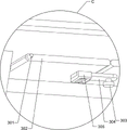
Fig. 12 is an enlarged schematic view of the part C of the present invention.
Fig. 13 is a schematic perspective view of the drainage mechanism of the present invention.
Fig. 14 is a perspective view of the automatic sewage discharging mechanism of the present invention.
Fig. 15 is an enlarged schematic view of the portion D of the present invention.
In the reference symbols: 1. a base, 2, a water purification tank, 3, an air storage cylinder, 4, an air guide pipe, 5, an aeration pump, 6, a fixing ring, 7, a cleaning pool, 8, a first spray pipe, 9, a first support frame, 10, a first water pump, 11, a support plate, 12, a tail water pool, 13, a guide plate, 14, a first sliding plate, 15, a first filter screen, 16, a filter pool, 17, a second filter screen, 18, a second spray pipe, 19, a second support frame, 20, a support block, 21, a third support frame, 22, a second water pump, 23, a residue barrel, 24, a first sliding rail, 25, a second sliding plate, 26, a fourth support frame, 27, a material pushing mechanism, 271, a first handle, 272, a first spring, 273, a push plate, 28, a blanking mechanism, 281, a push rod, 282, a first guide rod, a second spring, 284, a first fixing plate, 285, a first fixing block, 286, a top block, 287, a first rotating shaft, 283, a first torsion spring 288, 29. the automatic sewage draining device comprises a clamping mechanism, 291, a second handle, 292, a second fixed block, 293, a third spring, 30, a manual sewage draining mechanism, 301, a second rotating shaft, 302, a first baffle, 303, a third rotating shaft, 304, a clamping block, 305, a second fixed plate, 31, a water draining mechanism, 311, a fifth supporting frame, 312, a second baffle, 313, a second guide rod, 314, a fourth spring, 315, a wedge-shaped block, 316, a connecting rod, 317, a second sliding rail, 318, a fifth spring, 32, an automatic sewage draining mechanism, 321, a third fixed block, 322, a clamping rod, 323, a fixed rod, 324, a third fixed plate, 325, a sixth spring, 327 and a second torsion spring.
Detailed Description
It is to be noted that, in the case of the different described embodiments, identical components are provided with the same reference numerals or the same component names, wherein the disclosure contained in the entire description can be transferred to identical components having the same reference numerals or the same component names in a meaningful manner. The positional references selected in the description, such as upper, lower, lateral, etc., refer also to the directly described and illustrated figures and are to be read into the new position in the sense of a change in position.
Example 1
As shown in fig. 1, 2, 3 and 4, a water-saving walnut green shell recycling device comprises a base 1, a water purification tank 2, an air storage tank 3, an air duct 4, an aeration pump 5, a fixing ring 6, a cleaning tank 7, a first spray pipe 8, a first support frame 9, a first water pump 10, a support plate 11, a tail water tank 12, a guide plate 13, a first sliding plate 14, a first filter screen 15, a filter tank 16, a second filter screen 17, a second spray pipe 18, a second support frame 19, a support block 20, a third support frame 21, a second water pump 22, a residue tank 23, a first sliding rail 24, a second sliding plate 25, a fourth support frame 26, a pushing mechanism 27 and a blanking mechanism 28, wherein the water purification tank 2 is arranged on the front side and the rear side of the top of the base 1, the air storage tank 3 is arranged on the left front side of the base 1, the air duct 4 is arranged on the rear side of the upper portion of the air storage tank 3, the support block 20 is arranged on the top of the left side of the base 1, the top of the supporting block 20 is welded with a cleaning pool 7, the cleaning pool 7 is used for cleaning walnut green shells, the front side of the cleaning pool 7 is provided with a fixing ring 6, the fixing ring 6 is provided with an aeration pump 5, the tail end of an air duct 4 is connected with the upper part of the aeration pump 5, the left side and the right side between the two purified water tanks 2 are both provided with a first supporting frame 9 in a screw connection mode, a first spraying pipe 8 is arranged between the two first supporting frames 9, the first spraying pipe 8 is positioned at the top of the cleaning pool 7, the top of each of the two purified water tanks 2 is welded with a second supporting frame 19, a second spraying pipe 18 is arranged between the two second supporting frames 19, the second spraying pipe 18 is used for spraying clean water, the front and back of the top of the left side of the base 1 are symmetrically provided with third supporting frames 21 in a screw connection mode, the top ends of the two third supporting frames 21 are connected with the left side of the cleaning pool 7, a filter pool 16 is arranged between the right ends of the two third supporting frames 21, a guide plate 13 is connected between the left side of the top of the filtering tank 16 and the lower part of the right side of the cleaning tank 7, the same guide plate 13 is connected with the lower part of the right side of the filtering tank 16, a tail water tank 12 is arranged at the bottom of the guide plate 13 at the lower part, support plates 11 are symmetrically arranged at the left and right of the top of the tail water tank 12, a first water pump 10 is arranged between the tops of the two support plates 11, the tail end of a first spray pipe 8 is connected with the first water pump 10, a second filter screen 17 is arranged in the filtering tank 16 in a sliding manner, the second filter screen 17 is used for filtering broken slag, second water pumps 22 are arranged at the tops of the two water purification tanks 2, the end part of the second spray pipe 18 is connected with the upper part of the second water pump 22 at the same side, a residual slag barrel 23 is arranged at the top of the base 1, a handle is arranged at one side of the residual slag barrel 23, the residual slag barrel 23 is positioned below the filtering tank 16 and used for collecting broken slag, first slide rails 24 are symmetrically arranged at the front and back of the right side of the filtering tank 16, a first slide plate 14 is arranged between the two first slide rails 24 in a sliding manner, the lower part of the first sliding plate 14 is provided with a first filter screen 15, the right side of the cleaning pool 7 is slidably provided with a second sliding plate 25, the top of the base 1 is provided with a fourth supporting frame 26, the fourth supporting frame 26 is connected with the bottom of the filtering pool 16, the residue barrel 23 is slidably connected with the fourth supporting frame 26, the left side of the cleaning pool 7 is provided with a pushing mechanism 27, the pushing mechanism 27 is used for pushing out the cleaned walnut green shells, the inner wall of the right side of the cleaning pool 7 is provided with a blanking mechanism 28, the pushing mechanism 27 is matched with the blanking mechanism 28, and the blanking mechanism 28 is used for opening the cleaning pool 7.
When the green walnut shells need to be cleaned, a worker adds a certain amount of clean water into the clean water tank 2, after the cleaning, the worker pours the green walnut shells into the cleaning tank 7, then pours the clean water into the cleaning tank 7, after the cleaning, the worker plugs the tail water tank 12 with a tool, since the second filter screen 17 is of a sliding type, in order to avoid that the second filter screen 17 slides downwards under the action of gravity, the worker then fixes the second filter screen 17 at the middle part of the filter tank 16 with the tool, then the worker starts the aeration pump 5 again, the aeration pump 5 operates to discharge the gas in the gas storage cylinder 3 into the cleaning tank 7 through the gas guide tube 4, so that the clean water turns over to clean the rolled green walnut shells, after the cleaning, the worker pushes the pushing mechanism 27 to slide rightwards, so that the blanking mechanism 28 slides upwards to drive the second sliding plate 25 to slide upwards to open the cleaning tank 7, the material pushing mechanism 27 slides rightwards to push the cleaned walnut green shells out together with water, the walnut green shells and the water fall onto the second filter screen 17 through the guide plate 13 at the upper part, after the walnut green shells are completely pushed out, a worker loosens the material pushing mechanism 27, the material pushing mechanism 27 slides leftwards to reset, then the worker pushes the blanking mechanism 28 to slide downwards to reset to drive the second sliding plate 25 to slide downwards to reset to close the cleaning pool 7, after the walnut green shells fall onto the second filter screen 17, the worker starts the second water pump 22 to pump the clean water in the clean water tank 2 into the second spray pipe 18, the second spray pipe 18 sprays the clean water onto the walnut green shells to perform secondary cleaning, after the cleaning is completed, the worker closes the second walnut water pump 22, then takes down the tool, and then takes down the second filter screen 17 to collect the cleaned green shells, after the circulation of the walnut shells is completed, the worker puts back the second filter screen 17, the second filter screen 17 can filter the dregs of the walnut shells in the filter tank 16, the water in the filter tank 16 flows into the tail water tank 12 through the first filter screen 15 and the guide plate 13 at the lower part, the fine dregs can be filtered under the action of the first filter screen 15, a large amount of fine dregs remained in the water in the tail water tank 12 are avoided, when the worker pours the walnut shells into the cleaning tank 7 again, the worker starts the first water pump 10 to pump the used water in the tail water tank 12 into the first spray pipe 8, the first spray pipe 8 sprays the water onto the walnut shells, the walnut shells are cleaned, the circulation utilization purpose is achieved, after the utilization is completed, the worker closes the first water pump 10 and the aeration pump 5 to stop the operation, after the water in the tail water tank 12 is circulated and used for a plurality of times, the crew removes the tools from the tailrace pool 12 to release the waste water. This device simple structure, the staff pours the blue and green shell of walnut into cleaning tank 7 in and washs, and the blue and green shell of walnut after wasing drops and filters the disintegrating slag in filtering ponds 16, carries out the secondary through second shower 18 to the blue and green shell of walnut simultaneously and washs, takes out the water after using in the tail water pond 12 under first water pump 10 effect, sprays water to the blue and green shell of walnut on through first shower 8 to cyclic utilization's purpose has been reached.
Example 2
As shown in fig. 1, fig. 2, fig. 5, fig. 6, fig. 7 and fig. 8, on the basis of embodiment 1, the pushing mechanism 27 includes a first handle 271, a first spring 272 and a pushing plate 273, the first handle 271 is slidably disposed on the left side of the cleaning pool 7, the first spring 272 is symmetrically connected between the right side of the left portion of the first handle 271 and the left side of the cleaning pool 7 in a front-back manner, the right portion of the first handle 271 is welded with the pushing plate 273, the pushing plate 273 is located in the cleaning pool 7, and the pushing plate 273 is used for pushing the cleaned walnut shells.
The blanking mechanism 28 comprises a push rod 281, a first guide rod 282, a second spring 283, a first fixing plate 284, a first fixing block 285, a top block 286, a first rotating shaft 287 and a first torsion spring 288, push rod 281 is welded symmetrically around push pedal 273 top, cleaning tank 7 right side inner wall symmetry is provided with first guide arm 282 around, slidingtype is provided with first fixed plate 284 between two first guide arm 282, first fixed plate 284 is connected with second slide 25, all be connected with second spring 283 between both sides and the cleaning tank 7 around first fixed plate 284 bottom, second spring 283 initial condition is compression state, cleaning tank 7 top symmetry is provided with first fixed block 285 around the right side, the rotary type is provided with first pivot 287 between two first fixed blocks 285, the symmetry is provided with kicking block 286 around on the first pivot 287, push rod 281 and kicking block 286 cooperation, kicking block 286 and first fixed plate 284 cooperation, all be connected with first torsional spring 288 between kicking block 286 and the first fixed block 285 of homonymy.
After the walnut green shells are cleaned, a worker pushes the first handle 271 to slide rightwards, the first spring 272 is compressed, the first handle 271 slides rightwards to drive the push plate 273 to slide rightwards, the first spring 272 is compressed, the push plate 273 slides rightwards to drive the push rod 281 to move rightwards to extrude the top block 286 to swing rightwards, the first torsion spring 288 deforms accordingly, the top block 286 swings rightwards to not extrude the first fixing plate 284, the second spring 283 resets to drive the first fixing plate 284 to slide upwards, the first fixing plate 284 slides upwards to drive the second sliding plate 25 to slide upwards to open the cleaning pool 7, the push plate 273 slides rightwards to push out the walnut green shells and water together, the walnut green shells and the water fall onto the second filter screen 17 through the upper guide plate 13, after the walnut green shells are completely pushed out, the worker loosens the first handle 271, the first spring 272 resets to drive the first handle 271 to slide leftwards to reset, the first handle 271 slides leftwards to drive the push plate 273 to slide leftwards to reset, the push plate 273 slides leftwards to drive the push rod 281 to not extrude the top block 286 any more, then a worker pushes the first fixing plate 284 to slide downwards, the second spring 283 is compressed therewith, the first fixing plate 284 slides downwards to drive the second sliding plate 25 to slide downwards to close the cleaning pool 7, and after the first fixing plate 284 slides downwards to a certain distance, the first torsion spring 288 resets to drive the top block 286 to swing leftwards to limit the first fixing plate 284. This device simple structure, push plate 273 slides right and can be released the blue and green shell of walnut, and swing right through push rod 281 extrusion kicking block 286 simultaneously, make first fixed plate 284 upwards slide under the effect of second spring 283, and then realized that push plate 273 slides right when opening second slide 25 is automatic, reduced staff's work load.
Example 3
As shown in fig. 1, fig. 2, fig. 9, fig. 10, fig. 11, fig. 12, fig. 13, fig. 14, and fig. 15, based on embodiment 2, the present invention further includes a clamping mechanism 29, the clamping mechanism 29 includes a second handle 291, a second fixing block 292, and a third spring 293, the second handle 291 is slidably disposed on both front and rear sides of the filtering basin 16, clamping blocks are welded on opposite sides of the two second handles 291, the clamping blocks are matched with the second filtering net 17, the clamping blocks are used for clamping the second filtering net 17, the second fixing block 292 is disposed on both front and rear sides of the filtering basin 16, and the third spring 293 is symmetrically connected between the second handle 291 and the second fixing block 292 on the same side.
The push plate 273 slides rightwards to push out green walnut shells and water, then the green walnut shells and the water fall onto the second filter screen 17 through the guide plate 13 on the upper portion, clean water in the water purifying tank 2 is pumped into the second spray pipe 18 through the second water pump 22, the second spray pipe 18 sprays the clean water onto the green walnut shells for secondary cleaning, after cleaning is completed, a worker pulls the second handle 291 to slide backwards, the third spring 293 is compressed, the second handle 291 slides backwards and does not clamp the second filter screen 17, then the worker takes down the second filter screen 17 to collect the green walnut shells, after collection is completed, the worker puts the second filter screen 17 back, then the worker loosens the second handle 291 again, and the third spring 293 resets to drive the second handle 291 to slide backwards and clamp the second filter screen 17. This device simple structure can carry on spacingly to second filter screen 17 under the effect of second handle 291, avoids second filter screen 17 to slide down under the effect of gravity, no longer needs staff's use tools to fix.
Still including manual sewage disposal mechanism 30, manual sewage disposal mechanism 30 is including second pivot 301, first baffle 302, third pivot 303, fixture block 304 and second fixed plate 305, the symmetry rotary type is provided with second pivot 301 around filtering ponds 16 bottom, all be provided with first baffle 302 on two second pivots 301, first baffle 302 is used for switching filtering ponds 16, the first baffle 302 bottom front side of rear side is provided with third pivot 303, the rotation type is provided with fixture block 304 on the third pivot 303, first baffle 302 bottom rear side welding of front side has second fixed plate 305, fixture block 304 and second fixed plate 305 cooperate.
When more broken slag in the filtering tank 16 needs to be cleaned, a worker pushes the clamping block 304 to rotate and does not clamp the second fixing plate 305 any more, the first baffle plate 302 rotates downwards under the action of gravity to open the bottom of the filtering tank 16, the broken slag falls into the residual slag barrel 23 to be collected in a concentrated manner, then the worker pulls the first sliding plate 14 to slide upwards and take off the first sliding plate, the first filtering net 15 is cleaned, fine impurities are prevented from blocking the first filtering net 15, after the completion, the worker puts the first sliding plate 14 back, then pushes the first sliding plate 14 to slide downwards and reset, at the moment, the worker pushes the first baffle plate 302 to rotate upwards to close the bottom of the filtering tank 16, the worker pushes the clamping block 304 to rotate to clamp the second fixing plate 305 to limit the first baffle plate 302, and due to the handle arranged on the rear side of the residual slag barrel 23, the worker pulls the handle to drive the residual slag barrel 23 to slide backwards and take off the broken slag to be cleaned, after cleaning, the worker drives the residue barrel 23 to push back to reset by pushing the handle. This device simple structure, staff promote fixture block 304 and rotate and no longer block second fixed plate 305 for first baffle 302 rotates downwards under the effect of gravity and opens filtering ponds 16 bottom, and the disintegrating slag drops thereupon and concentrates the collection in the residue bucket 23, makes things convenient for the staff to clear up the disintegrating slag.
The water discharging mechanism 31 further comprises a water discharging mechanism 31, the water discharging mechanism 31 comprises a fifth support frame 311, a second baffle 312, a second guide rod 313, a fourth spring 314, a wedge block 315, a connecting rod 316, a second slide rail 317 and a fifth spring 318, the fifth support frame 311 is provided with the second guide rod 313, the second guide rod 313 is symmetrically provided with the second baffle 312 in a front-back sliding manner, the second baffle 312 is matched with the tail water pool 12, the second baffle 312 is used for opening and closing the tail water pool 12, the fourth spring 314 is symmetrically connected between opposite sides of the two second baffles 312 in a left-right manner, the second slide rail 317 is welded on the left side and the right side of the tail water pool 12, the wedge blocks 315 are arranged on the two second slide rails 317 in a sliding manner, the connecting rod 316 is arranged between the two wedge blocks 315, and the fifth springs 318 are symmetrically connected between the top of the wedge blocks 315 and the upper portions of the second slide rails 317 on the same side in a front-back manner.
When the water in the tailrace pool 12 needs to be released after being recycled for multiple times, a worker presses the connecting rod 316 to drive the wedge-shaped block 315 to slide downwards, the fifth spring 318 is stretched, the wedge-shaped block 315 slides downwards to press the second baffle 312 to slide backwards, the fourth spring 314 is stretched, the second baffle 312 slides backwards to open the tailrace pool 12, the wastewater in the tailrace pool 12 flows out along with the wedge-shaped block, after the wastewater is completed, the worker loosens the connecting rod 316, the fifth spring 318 resets along with the wedge-shaped block 315 to drive the wedge-shaped block 315 to slide upwards to reset and not to press the second baffle 312, and the fourth spring 314 resets along with the wedge-shaped block 312 to slide oppositely to reset to block the tailrace pool 12. This device simple structure, the staff makes wedge 315 lapse extrusion second baffle 312 and slides dorsad and open tailrace pond 12 through pressing connecting rod 316, makes things convenient for the staff to release waste water, no longer need use tools to plug up tailrace pond 12.
The automatic sewage draining mechanism 32 is further included, the automatic sewage draining mechanism 32 comprises a third fixing block 321, a clamping rod 322, a fixing rod 323, a third fixing plate 324, a sixth spring 325 and a second torsion spring 327, the third fixing block 321 is arranged at the bottom of the second fixing plate 305, the clamping rod 322 is slidably arranged on the third fixing block 321, the clamping rod 322 is matched with the clamping block 304, the fixing rod 323 is arranged at the bottom end of the clamping rod 322, the third fixing plate 324 is welded to the top of the wedge block 315 on the left side, the sixth spring 325 is connected between the top end of the clamping rod 322 and the third fixing block 321, the second torsion spring 327 is connected between the bottom of the clamping block 304 and the bottom end of the third rotating shaft 303, and the initial state of the second torsion spring 327 is a deformation state.
The wedge block 315 on the left side slides downwards to drive the third fixing plate 324 to move downwards, the third fixing plate 324 moves downwards to press the fixing rod 323, so as to drive the clamping rod 322 to slide downwards, the sixth spring 325 is compressed, the clamping rod 322 slides downwards without clamping the clamping block 304, the second torsion spring 327 resets to drive the clamping block 304 to rotate without clamping the second fixing plate 305, the first baffle 302 rotates downwards under the action of gravity to open the bottom of the filter tank 16, the broken slag falls into the residual slag barrel 23 for centralized collection, the wedge block 315 on the left side slides upwards to drive the third fixing plate 324 to move upwards for resetting, the sixth spring 325 resets to drive the clamping rod 322 to slide and reset, then the worker pushes the first baffle 302 to rotate upwards to close the bottom of the filter tank 16, the worker pulls the fixing rod 323 to drive the clamping rod 322 to slide downwards, the sixth spring 325 is compressed, the worker pushes the clamping block 304 to rotate to clamp the second fixing plate 305, the second torsion spring 327 deforms accordingly, and then the worker releases the fixing rod 323, and the sixth spring 325 resets accordingly to drive the clamping rod 322 to slide upwards to clamp the clamping block 304. This device simple structure, third fixed plate 324 moves down through extrusion dead lever 323 for card pole 322 no longer blocks fixture block 304, under second torsional spring 327's effect, and then has realized that fixture block 304 rotates automatically and no longer blocks second fixed plate 305 and open first baffle 302, and when avoiding artifical rotation fixture block 304 to open first baffle 302, the disintegrating slag dropped to staff's hand.
While the present invention has been described with reference to exemplary embodiments, it is to be understood that the invention is not limited to the disclosed exemplary embodiments. The scope of the following claims is to be accorded the broadest interpretation so as to encompass all such modifications and equivalent structures and functions.
Claims (8)
1. The utility model provides a green shell recycle device of walnut for water conservation, characterized by includes: the water purifying device comprises a base (1), wherein water purifying tanks (2) are arranged on the front side and the rear side of the top of the base (1); the air storage cylinder (3) is arranged on the front side of the left part of the base (1); the air guide pipe (4) is arranged at the rear side of the upper part of the air storage cylinder (3); the supporting block (20) is arranged at the top of the left side of the base (1); the top of the supporting block (20) is provided with the cleaning pool (7); the front side of the cleaning pool (7) is provided with a fixing ring (6); the aeration pump (5) is arranged on the fixing ring (6), and the tail end of the air duct (4) is connected with the upper part of the aeration pump (5); the left side and the right side between the two water purifying tanks (2) are respectively provided with a first support frame (9); the first spraying pipe (8) is arranged between the two first support frames (9), and the first spraying pipe (8) is positioned at the top of the cleaning pool (7); the top parts of the two water purifying tanks (2) are respectively provided with a second support frame (19); a second spray pipe (18), wherein a second spray pipe (18) is arranged between the two second support frames (19); the top of the left side of the base (1) is symmetrically provided with third support frames (21) in front and back, and the top ends of the two third support frames (21) are connected with the left side of the cleaning pool (7); the filtering tank (16) is arranged between the right ends of the two third supporting frames (21); the guide plate (13) is connected between the left side of the top of the filtering tank (16) and the lower part of the right side of the cleaning tank (7), and the same guide plate (13) is connected with the lower part of the right side of the filtering tank (16); the bottom of a guide plate (13) at the lower part of the tail water pool (12) is provided with the tail water pool (12); the supporting plates (11) are arranged at the top of the tail water pool (12) in a bilateral symmetry mode; the first water pump (10) is arranged between the tops of the two supporting plates (11), and the tail end of the first spray pipe (8) is connected with the first water pump (10); the second filter screen (17) is arranged in the filtering tank (16) in a sliding manner; the top parts of the two water purifying tanks (2) are respectively provided with a second water pump (22), and the end part of the second spray pipe (18) is connected with the upper part of the second water pump (22) at the same side; the slag barrel (23) is arranged at the top of the base (1), and the slag barrel (23) is positioned below the filtering tank (16); the first slide rails (24) are symmetrically arranged at the front and the back of the right side of the filter tank (16); the first sliding plate (14) is arranged between the two first sliding rails (24) in a sliding manner; the lower part of the first sliding plate (14) is provided with a first filter screen (15); the second sliding plate (25) is arranged on the right side of the cleaning pool (7) in a sliding manner; the top of the base (1) is provided with a fourth support frame (26), the fourth support frame (26) is connected with the bottom of the filtering tank (16), and the residue barrel (23) is connected with the fourth support frame (26) in a sliding manner; the left side of the cleaning pool (7) is provided with a material pushing mechanism (27); the blanking mechanism (28) is arranged on the inner wall of the right side of the cleaning pool (7), and the pushing mechanism (27) is matched with the blanking mechanism (28).
2. The water-saving walnut green shell recycling device as claimed in claim 1, wherein the material pushing mechanism (27) comprises: the first handle (271) is arranged on the left side of the cleaning pool (7) in a sliding manner; the first spring (272) is symmetrically connected between the right side of the left part of the first handle (271) and the left side of the cleaning pool (7) from front to back; the push plate (273), first handle (271) right part is provided with push plate (273), and push plate (273) are located cleaning pool (7).
3. The water-saving walnut green shell recycling device as claimed in claim 2, wherein the blanking mechanism (28) comprises: the push rods (281) are symmetrically arranged at the front and the back of the top of the push plate (273); the first guide rods (282) are symmetrically arranged at the front and the back of the inner wall of the right side of the cleaning pool (7); the first fixing plate (284) is arranged between the two first guide rods (282) in a sliding mode, and the first fixing plate (284) is connected with the second sliding plate (25); the second springs (283) are connected between the front side and the rear side of the bottom of the first fixing plate (284) and the cleaning pool (7), and the initial state of the second springs (283) is a compressed state; the cleaning device comprises a first fixed block (285), wherein the first fixed block (285) is symmetrically arranged at the front and back of the right side of the top of the cleaning pool (7); the first rotating shaft (287) is rotatably arranged between the two first fixed blocks (285); the first rotating shaft (287) is symmetrically provided with ejector blocks (286) in a front-back mode, the push rod (281) is matched with the ejector blocks (286), and the ejector blocks (286) are matched with the first fixing plate (284); and a first torsion spring (288) is connected between the first torsion spring (288) and the first fixing block (285) on the same side as the top block (286).
4. The water-saving walnut green shell recycling device as claimed in claim 3, further comprising a clamping mechanism (29), wherein the clamping mechanism (29) comprises: the front side and the rear side of the filter tank (16) are both provided with the second handles (291) in a sliding manner, and one opposite side of each of the two second handles (291) is provided with a clamping block which is matched with the second filter screen (17); the front side and the rear side of the filtering tank (16) are provided with second fixed blocks (292); and the third spring (293) is symmetrically connected between the second handle (291) and the second fixed block (292) on the same side left and right.
5. The walnut shell recycling device for saving water according to claim 4, further comprising a manual blowdown mechanism (30), wherein the manual blowdown mechanism (30) comprises: the second rotating shaft (301) is arranged at the bottom of the filtering tank (16) in a front-back symmetrical and rotating mode; the first baffle plates (302) are arranged on the two second rotating shafts (301); the third rotating shaft (303), the front side of the bottom of the first baffle (302) at the rear side is provided with the third rotating shaft (303); the fixture block (304) is rotationally arranged on the third rotating shaft (303); the second fixing plate (305) is arranged on the rear side of the bottom of the first baffle (302) on the front side, and the clamping block (304) is matched with the second fixing plate (305).
6. The water-saving walnut green shell recycling device as claimed in claim 5, further comprising a drainage mechanism (31), wherein the drainage mechanism (31) comprises: a fifth support frame (311), wherein a second guide rod (313) is arranged on the fifth support frame (311); the second baffle (312) is symmetrically arranged on the second guide rod (313) in a sliding manner from front to back, and the second baffle (312) is matched with the tail water pool (12); the fourth springs (314) are symmetrically connected between the opposite sides of the two second baffles (312) in a left-right mode; the left side and the right side of the tail water pool (12) are both provided with a second slide rail (317); the wedge blocks (315) are arranged on the two second sliding rails (317) in a sliding manner; the connecting rod (316) is arranged between the two wedge blocks (315); and fifth springs (318) are symmetrically connected between the tops of the wedge blocks (315) and the upper parts of the second slide rails (317) on the same side in a front-back mode.
7. The water-saving walnut green shell recycling device as claimed in claim 6, further comprising an automatic blowdown mechanism (32), wherein the automatic blowdown mechanism (32) comprises: a third fixed block (321), wherein the bottom of the second fixed plate (305) is provided with the third fixed block (321); the clamping rod (322) is arranged on the third fixing block (321) in a sliding mode, and the clamping rod (322) is matched with the clamping block (304); the bottom end of the clamping rod (322) is provided with the fixed rod (323); the top of the wedge block (315) on the left side is provided with a third fixing plate (324); a sixth spring (325), wherein the sixth spring (325) is connected between the top end of the clamping rod (322) and the third fixed block (321); and a second torsion spring (327) is connected between the bottom of the fixture block (304) and the bottom end of the third rotating shaft (303), and the initial state of the second torsion spring (327) is a deformation state.
8. The water-saving walnut green shell recycling device as claimed in claim 1, wherein a handle is arranged on one side of the residue barrel (23).
Priority Applications (1)
| Application Number | Priority Date | Filing Date | Title |
|---|---|---|---|
| CN202210084303.0A CN114472315B (en) | 2022-01-25 | 2022-01-25 | Walnut green husk recycling device for water conservation |
Applications Claiming Priority (1)
| Application Number | Priority Date | Filing Date | Title |
|---|---|---|---|
| CN202210084303.0A CN114472315B (en) | 2022-01-25 | 2022-01-25 | Walnut green husk recycling device for water conservation |
Publications (2)
| Publication Number | Publication Date |
|---|---|
| CN114472315A true CN114472315A (en) | 2022-05-13 |
| CN114472315B CN114472315B (en) | 2023-11-14 |
Family
ID=81474849
Family Applications (1)
| Application Number | Title | Priority Date | Filing Date |
|---|---|---|---|
| CN202210084303.0A Active CN114472315B (en) | 2022-01-25 | 2022-01-25 | Walnut green husk recycling device for water conservation |
Country Status (1)
| Country | Link |
|---|---|
| CN (1) | CN114472315B (en) |
Cited By (1)
| Publication number | Priority date | Publication date | Assignee | Title |
|---|---|---|---|---|
| CN115415236A (en) * | 2022-07-18 | 2022-12-02 | 嘉兴陶庄城市矿产资源有限公司 | Stainless steel metal recovery device and recovery method thereof |
Citations (8)
| Publication number | Priority date | Publication date | Assignee | Title |
|---|---|---|---|---|
| AU4885800A (en) * | 1999-08-03 | 2001-03-08 | Heat And Control Inc. | Simultaneous slicing and washing of vegetables |
| US20060127537A1 (en) * | 2004-07-15 | 2006-06-15 | Fresh Express Incorporated | Method and apparatus for coating fruit and vegetables |
| CN106736785A (en) * | 2017-02-17 | 2017-05-31 | 马宁 | A kind of drilling machine for being conveniently replaceable drill bit |
| CN206933249U (en) * | 2017-04-13 | 2018-01-30 | 姚安锦秋核桃果业有限公司 | A kind of green rind walnut decortication cleaning machine |
| CN210546972U (en) * | 2019-07-18 | 2020-05-19 | 天水兆达农业科技有限公司 | Walnut green shell recovery device |
| CN214267083U (en) * | 2020-11-16 | 2021-09-24 | 天津岳盈科技发展有限公司 | Ink cartridge fixing structure for ink-jet all-in-one machine |
| CN214962483U (en) * | 2021-06-09 | 2021-12-03 | 杜昌荣 | Novel green walnut peeling machine |
| CN113876001A (en) * | 2021-09-28 | 2022-01-04 | 卢荣帅 | Soybean belt cleaning device is used in soyfood production |
-
2022
- 2022-01-25 CN CN202210084303.0A patent/CN114472315B/en active Active
Patent Citations (8)
| Publication number | Priority date | Publication date | Assignee | Title |
|---|---|---|---|---|
| AU4885800A (en) * | 1999-08-03 | 2001-03-08 | Heat And Control Inc. | Simultaneous slicing and washing of vegetables |
| US20060127537A1 (en) * | 2004-07-15 | 2006-06-15 | Fresh Express Incorporated | Method and apparatus for coating fruit and vegetables |
| CN106736785A (en) * | 2017-02-17 | 2017-05-31 | 马宁 | A kind of drilling machine for being conveniently replaceable drill bit |
| CN206933249U (en) * | 2017-04-13 | 2018-01-30 | 姚安锦秋核桃果业有限公司 | A kind of green rind walnut decortication cleaning machine |
| CN210546972U (en) * | 2019-07-18 | 2020-05-19 | 天水兆达农业科技有限公司 | Walnut green shell recovery device |
| CN214267083U (en) * | 2020-11-16 | 2021-09-24 | 天津岳盈科技发展有限公司 | Ink cartridge fixing structure for ink-jet all-in-one machine |
| CN214962483U (en) * | 2021-06-09 | 2021-12-03 | 杜昌荣 | Novel green walnut peeling machine |
| CN113876001A (en) * | 2021-09-28 | 2022-01-04 | 卢荣帅 | Soybean belt cleaning device is used in soyfood production |
Cited By (1)
| Publication number | Priority date | Publication date | Assignee | Title |
|---|---|---|---|---|
| CN115415236A (en) * | 2022-07-18 | 2022-12-02 | 嘉兴陶庄城市矿产资源有限公司 | Stainless steel metal recovery device and recovery method thereof |
Also Published As
| Publication number | Publication date |
|---|---|
| CN114472315B (en) | 2023-11-14 |
Similar Documents
| Publication | Publication Date | Title |
|---|---|---|
| CN207567058U (en) | A kind of sanitary sewage disposal case being convenient to clean | |
| CN114472315B (en) | Walnut green husk recycling device for water conservation | |
| CN216997916U (en) | Municipal sewage circulation treatment equipment convenient to clearance sewage isolate | |
| CN113754108B (en) | Municipal wastewater treatment equipment convenient to residue in treatment wastewater | |
| CN208632136U (en) | Floating slag collecting device for sewage treatment | |
| CN114917645B (en) | Plastic pipe convenient for sewage disposal | |
| CN215782029U (en) | Sewage treatment filter equipment | |
| CN210313636U (en) | Oil-removing and slag-removing device for sewage treatment | |
| CN213760687U (en) | Sewage treatment device convenient to wash filter | |
| CN113786926A (en) | Full-automatic stripping off device of sediment matte | |
| CN209807088U (en) | A cylinder cleaning machine for rinsing vegetables | |
| CN113509770A (en) | Municipal efficient sewage treatment device and treatment method thereof | |
| CN218524014U (en) | Replacement device for ball number balls recovered by rubber ball pump | |
| CN214634401U (en) | Part belt cleaning device convenient to slagging-off | |
| CN114191866B (en) | Environment-friendly sewer wastewater treatment equipment | |
| CN217139438U (en) | Garbage filtering device for urban rainwater collection | |
| CN217661745U (en) | Slag removal device for waste liquid treatment | |
| CN215048732U (en) | Sediment machine is scraped with being convenient for empty formula sewage treatment | |
| CN218011357U (en) | Filtration and domestic sewage solid-liquid separation equipment | |
| CN215781935U (en) | Solid-liquid separation device for kitchen waste treatment | |
| CN214861632U (en) | Sewage filtering and recycling device for sewage treatment | |
| CN218451918U (en) | Sewage treatment integrated device convenient to clearance | |
| CN219363299U (en) | Water-saving facility for engineering construction | |
| CN219614996U (en) | Clear stifled machine of filtration liquid | |
| CN214551486U (en) | Integrated filter for sewage treatment |
Legal Events
| Date | Code | Title | Description |
|---|---|---|---|
| PB01 | Publication | ||
| PB01 | Publication | ||
| SE01 | Entry into force of request for substantive examination | ||
| SE01 | Entry into force of request for substantive examination | ||
| TA01 | Transfer of patent application right | ||
| TA01 | Transfer of patent application right |
Effective date of registration: 20230807 Address after: Room 211-215, Floor 2, Building 1, No. 69, Aoti Street, Jianye District, Nanjing City, Jiangsu Province, 210000 Applicant after: Nanjing Gemeida Technology Co.,Ltd. Address before: 510000 room 401-1399, No. 24, GUANGTANG West Road, Tianhe District, Guangzhou City, Guangdong Province Applicant before: Zhu Yuanyuan |
|
| GR01 | Patent grant | ||
| GR01 | Patent grant |