Disclosure of Invention
The invention aims to provide a submerged buoy device and a control method thereof, which are used for solving the technical problems that in the prior art, all functional units of the submerged buoy device are mutually separated and independent, different units need to be set and secondarily developed in advance according to application configuration, and the installation cost is high, the reliability is low and the installation is complicated.
The invention provides a submerged buoy device, which comprises: the underwater acoustic communication system comprises a packaging shell, a watertight cabin penetrating socket, an underwater acoustic communication main body, a data acquisition main body, a control main body and a mounting bracket;
a sealed cavity is accommodated in the packaging shell, the data acquisition main body, the control main body and the mounting bracket are all positioned in the sealed cavity, the mounting bracket is connected with the inside of the packaging shell, and the data acquisition main body and the control main body are all mounted on the mounting bracket;
one end of the watertight cabin penetrating socket penetrates through the packaging shell, the watertight cabin penetrating socket is connected with the packaging shell in a sealing mode, one end, extending into the sealed cavity, of the watertight cabin penetrating socket is electrically connected with the data acquisition main body, and the other end of the watertight cabin penetrating socket is used for being connected with an external sensor;
one end of the underwater acoustic communication main body penetrates through the packaging shell, the underwater acoustic communication main body is connected with the packaging shell in a sealing mode, and the underwater acoustic communication main body stretches into one end of the sealing cavity body and is respectively connected with the data acquisition main body and the control main body in an electric mode.
In a preferred embodiment of the present invention, the package housing comprises a fixed shell, a first end cap and a second end cap;
the first end cover and the second end cover are respectively positioned at two ends of the fixed shell, and the first end cover and the second end cover are respectively connected with the fixed shell in a sealing manner, so that a sealed cavity is formed inside the fixed shell;
the second end cover is provided with a first through hole, one end of the watertight cabin penetrating socket penetrates through the first through hole, the watertight cabin penetrating socket is connected with the second end cover, and the watertight cabin penetrating socket is in sealing connection with the first through hole.
In a preferred embodiment of the present invention, the underwater acoustic communication main body comprises an underwater acoustic communication control panel and an underwater acoustic communication transducer;
the first end cover is provided with a second through hole, one end of the underwater acoustic communication transducer penetrates through the second through hole, the other end of the underwater acoustic communication transducer is attached to the surface of the second end cover, the underwater acoustic communication transducer is connected with the first end cover, and the underwater acoustic communication transducer is connected with the second through hole in a sealing mode;
the underwater sound communication control panel is located in the sealed cavity, the underwater sound communication control panel is installed on the mounting bracket, and the underwater sound communication control panel is electrically connected with the underwater sound communication transducer through an enameled flat cable.
In a preferred embodiment of the present invention, the second through hole comprises a stepped groove;
the underwater acoustic communication transducer stretches into extremely seal chamber's one end with ladder groove joint, just the other end of underwater acoustic communication transducer with the surface laminating of first end cover is fixed.
In a preferred embodiment of the invention, the sealing device further comprises a first sealing body;
a first sealing groove is formed in the underwater acoustic communication transducer, a second sealing groove is correspondingly arranged on one side, away from the sealing cavity, of the first end cover, the second sealing groove is sleeved outside the second through hole, and the first sealing main body is respectively accommodated in the first sealing groove and the second sealing groove;
the first sealing groove is provided with an inclined surface from one end far away from the second sealing groove to the other end, the first sealing body is abutted against the inclined surface, and the inclined surface has a movement tendency of enabling the first sealing body to extrude the second sealing groove.
In a preferred embodiment of the present invention, the sealing device further comprises a second sealing body, a third sealing body and a fourth sealing body;
the second sealing body is positioned between the second end cover and the watertight bulkhead socket, and the second sealing body forms a seal with the first through hole through an end face to the watertight bulkhead socket;
the plurality of third sealing main bodies are sequentially sleeved outside the first end cover and are positioned between the first end cover and the fixed shell;
the fourth sealing main body is provided with a plurality of, and is a plurality of the fourth sealing main body is sheathed outside the second end cover in sequence, and the fourth sealing main body is positioned between the second end cover and the fixed shell.
In a preferred embodiment of the invention, the device further comprises a first guardrail and a second guardrail;
the first guardrail is connected with one side, far away from the fixed shell, of the first end cover, and the distance between the first guardrail and the first end cover is larger than the height of the underwater sound communication transducer extending out of the first end cover;
the second guardrail is connected with one side, far away from the fixed shell, of the second end cover, and the distance between the second guardrail and the second end cover is larger than the height of the watertight cabin penetrating socket extending out of the second end cover.
In a preferred embodiment of the present invention, the two ends of the watertight penetration socket are respectively provided with a connection terminal and a sealing socket, the watertight penetration socket is electrically connected to the data acquisition main body through the connection terminal and the flat cable, and the watertight penetration socket is electrically connected to an external sensor through the sealing socket.
In a preferred embodiment of the present invention, the material of the package housing is a titanium alloy material;
the fixed shell is fixedly connected with the first end cover through a titanium alloy bolt, and the fixed shell is fixedly connected with the second end cover through a titanium alloy bolt.
The invention provides a control method based on a submerged buoy device, which comprises the following steps:
the watertight cabin penetrating socket is connected with the sensor to establish communication connection;
conveying the information detected by the sensor to a control main body by using a data acquisition main body; the data acquisition main body can store the received information;
the control main body checks the received information;
starting the underwater acoustic communication main body, and performing digital/analog signal conversion on the data checked by the control main body;
and converting the analog signal into data of an acoustic signal for acoustic transmission communication.
The invention provides a submerged buoy device, which comprises: the underwater acoustic communication system comprises a packaging shell, a watertight cabin penetrating socket, an underwater acoustic communication main body, a data acquisition main body, a control main body and a mounting bracket; the data acquisition main body, the control main body and the mounting bracket are all positioned in the sealed cavity, and the mounting bracket is utilized to complete the mounting of the data acquisition main body and the control main body; on the basis of the sealing connection between the watertight cabin penetrating socket and the packaging shell, the watertight cabin penetrating socket can be electrically connected with the data acquisition main body and an external sensor; meanwhile, the underwater acoustic communication main body is hermetically connected with the packaging shell, the underwater acoustic communication main body is respectively and electrically connected with the data acquisition main body and the control main body, by integrating the watertight cabin-penetrating socket, the underwater acoustic communication main body, the data acquisition main body and the control main body on the packaging shell, the data of multiple sensors of different types in the submerged buoy device can be automatically acquired and processed, and the control main body can be used for carrying out adaptive scheduling and linkage control on the unification of all functional modules, therefore, one-stop full-automatic operation of transmitting all measured data to acoustic communication is realized, the integration, automation and intelligent application of a plurality of functional modules are realized, and the technical problems that in the prior art, all functional units of a submerged buoy device are mutually separated and independent, different units need to be set in advance according to application configuration and secondary development, and the installation cost is high, the reliability is low and the installation is complex are solved.
Detailed Description
The technical solutions of the present invention will be described clearly and completely with reference to the following embodiments, and it should be understood that the described embodiments are some, but not all, embodiments of the present invention. All other embodiments, which can be derived by a person skilled in the art from the embodiments given herein without making any creative effort, shall fall within the protection scope of the present invention.
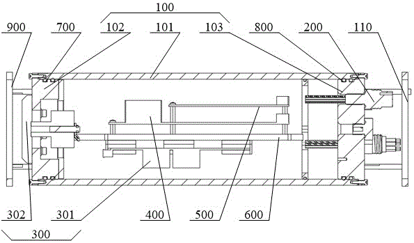
As shown in fig. 1 to 4, the present embodiment provides a submerged buoy apparatus, including: the underwater acoustic communication system comprises a packaging shell 100, a watertight cabin-penetrating socket 200, an underwater acoustic communication main body 300, a data acquisition main body 400, a control main body 500 and a mounting bracket 600; a sealed cavity is accommodated in the packaging shell 100, the data acquisition main body 400, the control main body 500 and the mounting bracket 600 are all positioned in the sealed cavity, the mounting bracket 600 is connected with the inside of the packaging shell 100, and the data acquisition main body 400 and the control main body 500 are all mounted on the mounting bracket 600; one end of the watertight penetration socket 200 penetrates through the packaging shell 100, the watertight penetration socket 200 is hermetically connected with the packaging shell 100, one end of the watertight penetration socket 200 extending into the sealed cavity is electrically connected with the data acquisition main body 400, and the other end of the watertight penetration socket 200 is used for being connected with an external sensor; one end of the underwater acoustic communication main body 300 penetrates through the packaging shell 100, the underwater acoustic communication main body 300 is hermetically connected with the packaging shell 100, and one end of the underwater acoustic communication main body 300 extending into the sealed cavity is electrically connected with the data acquisition main body 400 and the control main body 500 respectively.
It should be noted that the submerged buoy apparatus provided in this embodiment belongs to an integrated apparatus formed by data acquisition and control assembly of multiple sensors and underwater acoustic communication transmission, specifically, the enclosure 100 may form a watertight pressure-resistant cabin, the data acquisition main body 400 and the control main body 500 are fixed in a sealed cavity of the enclosure 100 through the mounting bracket 600, the watertight bulkhead-penetrating socket 200 is hermetically mounted on the enclosure 100, the watertight bulkhead-penetrating socket 200 can be used as a connection main body of an external sensor, the external sensor and the data acquisition main body 400 are electrically connected in watertight pressure-resistant manner by using the watertight bulkhead-penetrating socket 200, and the underwater acoustic communication main body 300 is hermetically mounted in the enclosure 100, the underwater acoustic communication main body 300 can form watertight pressure-resistant electrical connection with the control main body 500, thereby completing power supply, control signal and data connection of the external sensor and the power supply, and realizing multifunctional integrated application, the water leakage and wrong connection risks in split design are avoided, the defects that in the prior art, all functional units are mutually independent and cannot be uniformly and quickly set and adapt to different application scenes are overcome, the integration, automation and intelligent application of a plurality of functional modules are realized, the uncertainty caused by independent setting and system matching of each module by a user is avoided, the use efficiency and the reliability are improved, the integration level of the whole machine is high, the whole size is small, and the installation convenience and the operation practicability in deep sea use scenes are improved.
It should be noted that the data acquisition main body 400 provided in this embodiment may adopt a data acquisition and storage board, and the control main body 500 may adopt a system main control board, where the models of the data acquisition main body 400 and the control main body 500 may adopt structures that belong to a submerged buoy apparatus and can realize the functions thereof, and details thereof are not described here.
The embodiment provides a submerged buoy device, includes: the underwater acoustic communication device comprises a packaging shell 100, a watertight penetration socket 200, an underwater acoustic communication main body 300, a data acquisition main body 400, a control main body 500 and a mounting bracket 600; the data acquisition main body 400, the control main body 500 and the mounting bracket 600 are all positioned in the sealed cavity, and the mounting bracket 600 is utilized to complete the mounting of the data acquisition main body 400 and the control main body 500; on the basis of the sealing connection between the watertight penetration socket 200 and the packaging shell 100, the watertight penetration socket 200 can also be electrically connected with the data acquisition main body 400 and connected with an external sensor; meanwhile, the underwater acoustic communication main body 300 is hermetically connected with the packaging shell 100, the underwater acoustic communication main body 300 is respectively and electrically connected with the data acquisition main body 400 and the control main body 500, the watertight cabin-penetrating socket 200, the underwater acoustic communication main body 300, the data acquisition main body 400 and the control main body 500 are integrated on the packaging shell 100, so that the multi-sensor data of different types in the submerged buoy device can be automatically acquired and processed, the control main body 500 is used for carrying out adaptive adjustment and linkage control on the unification of all the functional modules, the one-station full-automatic operation of all the measurement data to acoustic communication transmission is realized, the integration, automation and intelligent application of a plurality of functional modules are realized, the problem that all the functional units of the submerged buoy device in the prior art are mutually separated and independent, different units need to be preset and secondarily developed according to application configuration, and the installation cost is high is solved, Low reliability and complex installation.
On the basis of the above embodiment, further, in the preferred embodiment of the present invention, the package housing 100 includes a fixed casing 101, a first end cap 102 and a second end cap 103; the first end cover 102 and the second end cover 103 are respectively located at two ends of the fixed casing 101, and the first end cover 102 and the second end cover 103 are respectively connected with the fixed casing 101 in a sealing manner, so that a sealed cavity is formed inside the fixed casing 101; the second end cover 103 is provided with a first through hole, one end of the watertight cabin penetrating socket 200 penetrates through the first through hole, the watertight cabin penetrating socket 200 is connected with the second end cover 103, and the watertight cabin penetrating socket 200 is in sealing connection with the first through hole.
In a preferred embodiment of the present invention, the material of the package housing 100 is a titanium alloy material; the fixed housing 101 and the first end cap 102 are fixedly connected by a titanium alloy bolt, and the fixed housing 101 and the second end cap 103 are fixedly connected by a titanium alloy bolt.
In this embodiment, the fixed casing 101 may be a drum casing, and the first end cap 102 and the second end cap 103 may form a sealing connection with two ends of the drum casing, preferably, the fixed casing 101 may be a titanium alloy drum casing, the first end cap 102 is a titanium alloy top end cap, the second end cap 103 is a titanium alloy bottom end cap, the titanium alloy top end cap and the titanium alloy drum casing are mechanically and fixedly connected through a titanium alloy bolt, the titanium alloy bottom end cap and the titanium alloy drum casing are mechanically connected through a titanium alloy bolt, the pressure resistance of the package casing 100 in deep sea can be ensured through the titanium alloy material, meanwhile, the fixed casing 101 is tightly and mechanically connected with the first end cover 102 and the second end cover 103 respectively by using titanium alloy bolts, thereby being capable of satisfying the requirement of fixing the data collection main body 400 and the control main body 500 in the sealed cavity of the package case 100 through the mounting bracket 600; in addition, alternatively, the mounting bracket 600 may also be fixedly connected to the inner wall of the first end cap 102 or the second end cap 103 by means of bolts, so that the mounting bracket 600 can be fixed inside the sealed cavity of the package housing 100.
In the preferred embodiment of the present invention, the underwater acoustic communication main body 300 includes an underwater acoustic communication control board 301 and an underwater acoustic communication transducer 302; a second through hole is formed in the first end cover 102, one end of the underwater acoustic communication transducer 302 penetrates through the second through hole, the other end of the underwater acoustic communication transducer 302 is attached to the surface of the second end cover 103, the underwater acoustic communication transducer 302 is connected with the first end cover 102, and the underwater acoustic communication transducer 302 is hermetically connected with the second through hole; the underwater acoustic communication control panel 301 is located in the sealed cavity, the underwater acoustic communication control panel 301 is installed on the mounting bracket 600, and the underwater acoustic communication control panel 301 is electrically connected with the underwater acoustic communication transducer 302 through an enameled flat cable.
In this embodiment, the underwater acoustic communication control panel 301 is mounted on the mounting bracket 600, and the data collection main body 400 and the control main body 500 are electrically connected through the inter-board connector of the mounting bracket 600, and is electrically connected with the underwater acoustic communication control panel 301 through a flat cable to complete the connection of power supply, control signals and data, wherein, the underwater acoustic communication transducer 302 can convert the signal of the control body 500 received by the underwater acoustic communication control board 301, convert the digital signal into an analog acoustic signal and transmit the analog acoustic signal in the sea water, and one end of the underwater acoustic communication transducer 302 penetrates through the first end cap 102, the underwater acoustic communication transducer 302 is hermetically connected with the first through hole of the first end cap 102, that is, the underwater acoustic communication transducer 302 can realize the waterproof sealing function between the underwater acoustic communication transducer 302 and the sealed cavity on the basis of ensuring the electrical connection with the underwater acoustic communication control panel 301.
In a preferred embodiment of the present invention, the second through-hole comprises a stepped groove; one end of the underwater acoustic communication transducer 302 extending into the sealed cavity is clamped with the stepped groove, and the other end of the underwater acoustic communication transducer 302 is attached and fixed to the surface of the first end cover 102.
In a preferred embodiment of the invention, the sealing device further comprises a first sealing body; a first sealing groove 312 is formed in the underwater acoustic communication transducer 302, a second sealing groove is correspondingly arranged on one side of the first end cover 102, which is far away from the sealing cavity, the second sealing groove is sleeved outside the second through hole, and the first sealing main body is respectively accommodated in the first sealing groove 312 and the second sealing groove; the first seal groove 312 has an inclined surface along the end away from the second seal groove to the other end, the first seal body abuts against the inclined surface, and the inclined surface has a movement tendency that the first seal body presses the second seal groove.
In this embodiment, the first sealing body may be an O-ring, specifically, one end of the underwater acoustic communication transducer 302 extending into the sealing cavity is clamped with the stepped groove, wherein the underwater acoustic communication transducer 302 may include two parts, one part of the underwater acoustic communication transducer 302 is inserted into the second through hole along one side of the sealing cavity away from the first end cap 102, the other part of the underwater acoustic communication transducer 302 can be mechanically and fixedly connected with the part inserted into the second through hole, and the underwater acoustic communication transducer 302 located in the stepped groove can be electrically connected with the underwater acoustic communication control board 301; when the underwater acoustic communication transducer 302 is connected with the first end cap 102, the side of the first end cap 102 away from the sealed cavity is tightly attached by clamping the O-ring inside the first sealing groove 312 and the second sealing groove and by using the underwater acoustic communication transducer 302; further, through having arranged the inclined plane at first seal groove 312, the inclined plane and the butt of O type sealing washer, utilize the inclined plane can be better exert extrusion effort to O type sealing washer, simultaneously, receive deep sea water pressure effect when first end cover 102, the inclined plane is under the elastic force of O type sealing washer, the effort of deflecting can be exerted to the inclined plane for first sealed main part can be along oblique effort extrusion second seal groove, thereby the end face seal mode of assurance O type sealing washer that can be better realizes withstand voltage and waterproof sealing function.
In the preferred embodiment of the present invention, a second sealing body, a third sealing body 700 and a fourth sealing body 800 are further included; the second sealing body is positioned between the second end cover 103 and the watertight penetration socket 200, and the second sealing body forms sealing with the watertight penetration socket 200 and the first through hole through the end face; a plurality of third sealing bodies 700 are provided, the plurality of third sealing bodies 700 are sequentially sleeved outside the first end cover 102, and the third sealing bodies 700 are located between the first end cover 102 and the fixed housing 101; the plurality of fourth sealing bodies 800 are provided, the plurality of fourth sealing bodies 800 are sequentially sleeved outside the second end cap 103, and the fourth sealing bodies 800 are located between the second end cap 103 and the fixed housing 101.
In this embodiment, the second, third and fourth sealing bodies 700 and 800 may all adopt O-ring seals, wherein, after the watertight penetration socket 200 penetrates the first through hole, the end face of the watertight penetration socket 200 is attached to the surface of the second end cap 103, a sealing groove may be formed on the surface of the second end cap 103, and on the basis that the inner diameter of the second sealing body is greater than the inner diameter of the first through hole, the second sealing body is clamped in the sealing groove, and the second sealing body that is an O-ring seal realizes the pressure-resistant and waterproof sealing functions by adopting an end face sealing manner.
Optionally, 2 third seal bodies 700 may be adopted, and a radial sealing manner in which 2O-ring seals are annularly sleeved on the outer side of the first end cover 102 is utilized to realize pressure-resistant and waterproof sealing functions; similarly, the number of the fourth sealing bodies 800 may be 2, and the radial sealing manner in which 2O-rings are annularly sleeved on the outer side of the second end cover 103 is utilized to achieve the pressure-resistant and waterproof sealing functions.
It should be noted that, since the underwater acoustic communication body 300 and the watertight penetration socket 200 extend out of the end portions of the two ends of the enclosure 100 during the operation of the enclosure 100 in the deep sea, in order to prevent the underwater acoustic communication body 300, the watertight penetration socket 200 and other electrical connection wires from colliding with solid matters in the deep sea and causing unnecessary loss, in the preferred embodiment of the invention, the enclosure further includes a first guardrail 900 and a second guardrail 110; the first guardrail 900 is connected with one side of the first end cover 102 far away from the fixed casing 101, and the distance between the first guardrail 900 and the first end cover 102 is larger than the height of the underwater acoustic communication transducer 302 extending out of the first end cover 102; the second guardrail 110 is connected with the side of the second end cap 103 far away from the fixed casing 101, and the distance between the second guardrail 110 and the second end cap 103 is larger than the height of the watertight penetration socket 200 extending out of the second end cap 103.
Optionally, the first protection fence 900 can be connected to the first end cap 102 in various ways, such as being plugged, riveted or connected by bolts, and preferably, the first protection fence 900 is connected to the first end cap 102 by bolts; similarly, the second protection rail 110 and the second end cap 103 can be connected in various ways, such as by plugging, riveting or bolting, and preferably, the second protection rail 110 and the second end cap 103 are connected by bolting.
In a preferred embodiment of the present invention, the two ends of the watertight penetration socket 200 are respectively provided with a terminal and a sealed socket, the watertight penetration socket 200 is electrically connected to the data acquisition main body 400 through the terminal and the flat cable, and the watertight penetration socket 200 is used for electrically connecting to an external sensor through the sealed socket.
In this embodiment, since the package casing 100 integrates all functional modules of data acquisition, system bus control, and acoustic communication, only a sensor data acquisition interface is provided externally, the watertight penetration socket 200 is utilized to perform electrical connection through the wiring terminal and the flat cable, the power supply and signal connection functions of the data acquisition main body 400, the external sensor and the power supply unit are completed, each unit is connected through the flat cable, the water leakage and the wrong connection risk of split design are avoided, one-key setting and simple operation of plug and play are realized, the acoustic transmission device is suitable for rapid deployment of different sensor accesses and different application scenes, and full-automatic operation of acoustic transmission for data acquisition is realized.
The control method of the submerged buoy device based on the embodiment comprises the following steps: the watertight cabin-penetrating socket 200 is connected with a sensor to establish communication connection; the information detected by the sensor is conveyed to the control body 500 by the data acquisition body 400; wherein, the data acquisition main body 400 can store the received information; the control main body 500 checks the received information; starting the underwater acoustic communication main body 300, and performing digital/analog signal conversion on the data checked by the control main body 500; and converting the analog signal into data of an acoustic signal for acoustic transmission communication.
In this embodiment, an RS232 serial communication connection is established with the watertight penetration socket 200 through a watertight cable, the data acquisition main body 400 is responsible for acquiring and storing measurement data of all sensors, and sending acquired data information to the control main body 500 through the RS232 serial communication connection, the control main body 500 checks and checks the data acquired by the data acquisition main body 400, packages and packs all sensor data as good as possible and controls the underwater acoustic communication control panel 301 to start, and converts digital signals into analog acoustic signals through the underwater acoustic communication transducer 302 to transmit in seawater; according to the control method of the submerged buoy device based on the embodiment, data acquisition and underwater acoustic communication transmission of multiple sensors can be integrally set, so that the defects that all function units are mutually independent and cannot be uniformly and quickly set and adapt to different application scenes in the prior art are overcome, automatic acquisition and storage can be carried out on different types of data of the multiple sensors in the submerged buoy device, and self-adaptive scheduling and linkage control are carried out on the unification of all function modules, so that one-stop full-automatic operation from all measured data to acoustic communication transmission is realized, the integration, automation and intelligent application of the multiple function modules are realized, the uncertainty caused by independent setting and system matching of each module by a user is avoided, and the use efficiency and reliability are improved.
Finally, it should be noted that: the above embodiments are only used to illustrate the technical solution of the present invention, and not to limit the same; while the invention has been described in detail and with reference to the foregoing embodiments, it will be understood by those skilled in the art that: the technical solutions described in the foregoing embodiments may still be modified, or some or all of the technical features may be equivalently replaced; and the modifications or the substitutions do not make the essence of the corresponding technical solutions depart from the scope of the technical solutions of the embodiments of the present invention.