CN114460812A - Structure and method for mounting suck-back valve - Google Patents
Structure and method for mounting suck-back valve Download PDFInfo
- Publication number
- CN114460812A CN114460812A CN202210370926.4A CN202210370926A CN114460812A CN 114460812 A CN114460812 A CN 114460812A CN 202210370926 A CN202210370926 A CN 202210370926A CN 114460812 A CN114460812 A CN 114460812A
- Authority
- CN
- China
- Prior art keywords
- valve
- baffle
- suck
- limiting
- suckback
- Prior art date
- Legal status (The legal status is an assumption and is not a legal conclusion. Google has not performed a legal analysis and makes no representation as to the accuracy of the status listed.)
- Granted
Links
Images


Classifications
-
- G—PHYSICS
- G03—PHOTOGRAPHY; CINEMATOGRAPHY; ANALOGOUS TECHNIQUES USING WAVES OTHER THAN OPTICAL WAVES; ELECTROGRAPHY; HOLOGRAPHY
- G03F—PHOTOMECHANICAL PRODUCTION OF TEXTURED OR PATTERNED SURFACES, e.g. FOR PRINTING, FOR PROCESSING OF SEMICONDUCTOR DEVICES; MATERIALS THEREFOR; ORIGINALS THEREFOR; APPARATUS SPECIALLY ADAPTED THEREFOR
- G03F7/00—Photomechanical, e.g. photolithographic, production of textured or patterned surfaces, e.g. printing surfaces; Materials therefor, e.g. comprising photoresists; Apparatus specially adapted therefor
- G03F7/16—Coating processes; Apparatus therefor
Abstract
The invention discloses a mounting structure and a method of a suck-back valve, wherein the mounting structure of the suck-back valve comprises the following components: the back suction valve is arranged on the mounting panel; at least one installation unit, the installation unit locate the installation panel, the installation unit includes: the first limiting piece is arranged on the mounting panel and limited on the first side surface of the suck-back valve; the second limiting piece is arranged on the mounting panel and limited on a second side surface of the suck-back valve, and a plane where the first side surface is located is crossed with a plane where the second side surface is located; the cover plate assembly covers the top of the suckback valve, and the cover plate assembly is detachably connected with at least one of the first limiting part, the second limiting part and the installation panel and tightly presses the suckback valve on the installation panel. The invention solves the problems that the installation space of the suck-back valve is limited, all fixing parts of the suck-back valve are difficult to disassemble, and the suck-back valve is difficult to replace.
Description
Technical Field
The invention relates to the field of wafers in the semiconductor industry, in particular to a mounting structure and a mounting method of a suck-back valve.
Background
The suck-back valve is a device which can control liquid in a negative pressure suck-back mode to carry out processes such as pouring, smearing, spraying and the like. In the glue homogenizing process of the wafer in the semiconductor industry, the suck-back valve can be used for cleaning a glue nozzle and other processes through electric control.
At present, the suck-back valve is installed on the installation panel through a fixing piece, the suck-back valve and the installation panel are placed into the spin coating developing equipment together for pipeline connection, but the installation space of the spin coating developing equipment is limited, and the disassembly and locking of all the fixing pieces cannot be carried out in the installation space of the spin coating developing equipment, so that the suck-back valve cannot be directly replaced and fixed.
Disclosure of Invention
Therefore, the invention provides a mounting structure and a mounting method of a suckback valve, which effectively solve the problems that the suckback valve is limited in mounting space, all fixing pieces of the suckback valve are difficult to disassemble, and the suckback valve is difficult to replace.
In one aspect, the present invention provides a suck-back valve mounting structure, including: the back suction valve is arranged on the mounting panel; at least one mounting unit, the mounting unit is located the mounting panel for install the suckback valve, the mounting unit includes: the first limiting piece is arranged on the mounting panel and limited on the first side surface of the suck-back valve; the second limiting piece is arranged on the mounting panel and limited on a second side surface of the suck-back valve, and a plane where the first side surface is located is crossed with a plane where the second side surface is located; the cover plate assembly covers the top of the suckback valve, the cover plate assembly is detachably connected with at least one of the first limiting part, the second limiting part and the installation panel, and the suckback valve is pressed on the installation panel through the cover plate assembly.
The technical effect achieved after the technical scheme is adopted is as follows: the first limiting piece and the second limiting piece can limit the horizontal position of the suckback valve, so that the suckback valve is prevented from being loosened transversely, and the stability of a pipeline is improved; the cover plate component compresses the suckback valve, so that the stability of the suckback valve is further improved; wherein, the apron subassembly can with first locating part, second locating part or mounting panel connects, and when dismantling the suckback valve, only need loosen the connection of apron subassembly and other parts, and take off the apron subassembly, can carry out the dismantlement and the change of suckback valve, install once more during the suckback valve, only need fix the apron subassembly, consequently improved the dismouting efficiency of suckback valve is convenient for the maintenance and the change of suckback valve.
Further, the cover plate assembly includes: the cover plate is detachably connected with the top of the suckback valve; the first baffle is arranged on a first side face, the first baffle is detachably connected with the first limiting piece, the second baffle is arranged on a second side face, and the second baffle is detachably connected with the second limiting piece.
The technical effect achieved after the technical scheme is adopted is as follows: the first baffle is used for further limiting the first side surface of the suck-back valve, after the first baffle is arranged, the longitudinal size of the first limiting piece does not need to be too high, and the first limiting piece and the first baffle can be connected to stably limit the first side surface; similarly, the second baffle is used for further limiting the second side surface of the suck-back valve, after the second baffle is arranged, the longitudinal size of the second limiting part does not need to be too high, and the second limiting part and the second baffle can be connected to stably limit the second side surface.
Further, the first baffle and the second baffle are connected to each other, and at least one of the first baffle and the second baffle is connected to the cover plate; or the first baffle plate and the second baffle plate are separated, and the first baffle plate and the second baffle plate are both connected with the cover plate.
The technical effect achieved after the technical scheme is adopted is as follows: after the cover plate is connected with at least one of the first baffle plate and the second baffle plate, the cover plate is connected with the first limiting piece by combining the first baffle plate, and the second baffle plate is connected with the second limiting piece, so that the cover plate is fixed; after the first baffle and the second baffle are connected, the stability of the cover plate is further improved; at the moment, the cover plate is connected with the top of the suck-back valve through a fastener, and the suck-back valve can be fixed.
Further, the suckback valve comprises: the device comprises an electric control device, a cable and a first interface, wherein the cable and the first interface are positioned on the side surface of the electric control device; the first baffle is located on the other side, opposite to the cable, of the electric control device, and the first baffle comprises a first avoidance position, and the first avoidance position is used for avoiding the first interface.
The technical effect achieved after the technical scheme is adopted is as follows: after the first side face of the suckback valve is limited by the first baffle, as long as the suckback valve is tightly pressed by the cover plate, the other side face of the suckback valve relative to the first side face does not need to be limited again; one side of the suck-back valve, which is far away from the cable, can provide a larger contact area, so that the first baffle plate can limit the position conveniently; the first avoidance position is convenient for the first interface extends out and is connected with a corresponding pipeline, and meanwhile, when the first interface is connected with or detached from the corresponding pipeline, the first avoidance position can provide a larger operation space.
Further, the suckback valve comprises: the valve comprises a valve body and second interfaces, wherein the second interfaces are positioned on two opposite sides of the valve body; the second baffle is located on one side adjacent to the second interface and comprises a second avoidance position used for avoiding the second interface.
The technical effect achieved after the technical scheme is adopted is as follows: the adjacent side of the second interface is convenient for the second baffle to limit; the second baffle can limit the valve body and the electric control device simultaneously in a direction perpendicular to the first baffle, so that the stability of the suckback valve is further improved; the second dodges the position and is in the second interface side, for the dismouting of second interface provides bigger operating space.
Further, the first limiting member includes: the first limiting plate faces the first side face, and the first fixing plate is connected with the mounting panel; and/or, the second limiting member comprises: the second limiting plate faces the second side face, and the second fixing plate is connected with the mounting panel.
The technical effect achieved after the technical scheme is adopted is as follows: the first fixing plate is used for fixing the first limiting piece to the installation panel, and the second fixing plate is used for fixing the second limiting piece to the installation panel; the side, far away from the first fixing plate, of the first limiting plate and the side, far away from the second fixing plate, of the second limiting plate form an installation space for accommodating the suckback valve; in the disassembly and assembly process of the suckback valve, the suckback valve can be taken and placed along the vertical movement of the first limiting plate and the second limiting plate without taking down the first limiting part and the second limiting part, so that the suckback valve is convenient to disassemble and assemble.
Further, the first limiting plate comprises a first fixing hole, the first baffle plate comprises a first through hole, and the first fixing hole and the first through hole are connected through a first fastener; and/or, the second limiting plate comprises a second fixing hole, the second baffle plate comprises a second through hole, and the second fixing hole is connected with the second through hole through a second fastener.
The technical effect achieved after the technical scheme is adopted is as follows: the first fixing hole and the first through hole realize the quick fixation of the first baffle and the first limiting plate; the second fixing hole and the second through hole realize the quick fixation of the second baffle and the second limiting plate; meanwhile, the first baffle and the first limiting plate are both in a vertical state.
Further, the first fixing hole and the second fixing hole are provided with openings which are vertically upward.
The technical effect achieved after the technical scheme is adopted is as follows: before the suck-back valve is disassembled, the first fastener and the second fastener are not required to be removed, the first fastener and the second fastener are in a loose state, the cover plate, the first baffle plate and the second baffle plate can be upwards taken out, the first fastener and the second fastener move upwards along with the first fastener and the second fastener, and the first fastener and the second fastener are separated from the first fixing hole and the second fixing hole from the opening.
Furthermore, a plurality of the installation units are arranged along the length direction of the first limiting piece to form a row of installation modules, and a first accommodating space is formed between every two adjacent installation units in the installation modules.
The technical effect achieved after the technical scheme is adopted is as follows: the mounting units are mounted on the mounting panel in a multi-row arrangement mode, so that the space utilization rate can be improved; the first accommodating space is used for accommodating the adjacent cables of the installation modules, namely the adjacent installation modules and the installation units are arranged in a staggered mode, and the cables are prevented from being bent excessively.
On the other hand, the invention also provides a back suction valve installation method, which is realized by the back suction valve installation structure provided by any technical scheme, and the back suction valve installation method comprises the following steps: mounting the first and second stoppers to the mounting panel; placing the suck-back valve on the installation panel, and limiting through the first limiting piece and the second limiting piece; and pressing the cover plate assembly against the suck-back valve to lock the cover plate assembly.
The technical effect achieved after the technical scheme is adopted is as follows: after the suck-back valve is placed in the suck-back valve mounting structure, the cover plate assembly is locked, and then the suck-back valve can be stably connected with the mounting panel; when the suck-back valve is disassembled, the cover plate assembly is loosened, and the cover plate assembly is taken down together, so that the suck-back valve can be disassembled.
In summary, the above technical solutions of the present application may have one or more of the following advantages or beneficial effects: i) the first limiting piece and the second limiting piece can limit the horizontal position of the suckback valve, the first fastening piece is connected with the first limiting plate and the first baffle, and the second fastening piece is connected with the second limiting plate and the second baffle, so that the stability of the suckback valve is further improved; ii) when the suck-back valve is installed, the cover plate assembly is vertically installed along the direction of the first fixing hole and the second fixing hole, the suck-back valve is tightly pressed, and the cover plate and the suck-back valve are fixed, so that the installation efficiency is high, and similarly, when the suck-back valve is disassembled, the cover plate assembly and the suck-back valve can be sequentially taken down only by loosening the connection between the cover plate and the suck-back valve, so that the disassembly efficiency is high; iii) the installation units of the adjacent installation modules are arranged in a staggered manner, so that the first accommodating space can accommodate the adjacent cables of the installation modules, the space utilization rate is improved, and the cables are prevented from being excessively bent.
Drawings
In order to more clearly illustrate the technical solutions of the embodiments of the present invention, the drawings needed to be used in the description of the embodiments are briefly introduced below, and it is obvious that the drawings in the following description are only some embodiments of the present invention, and it is obvious for those skilled in the art to obtain other drawings based on these drawings without creative efforts.
Fig. 1 is a schematic structural diagram of a suckback valve mounting structure according to a first embodiment of the present invention.
Fig. 2 is a schematic structural view of the mounting unit of fig. 1.
Fig. 3 is a schematic structural view of the mounting unit in fig. 2 from another perspective.
Fig. 4 is a schematic structural view of the cover plate assembly of fig. 2.
Fig. 5 is a schematic structural diagram of the first limiting member in fig. 2.
Fig. 6 is a schematic structural diagram of the second limiting member in fig. 2.
FIG. 7 is a schematic view of the mounting structure of the suckback valve of FIG. 1 from another perspective.
Fig. 8 is a flowchart of a method for installing a suckback valve according to a second embodiment of the present invention.
Description of the main element symbols:
10 is a suck-back valve; 11 is a first side surface; 12 is a second side; 13 is an electric control device; 14 is a cable; 15 is a first interface; 16 is a valve body; 17 is a second interface; 100 is a suck-back valve mounting structure; 101 is an installation module; 110 is a mounting panel; 120 is a mounting unit; 130 is a first limiting member; 131 is a first limit plate; 132 is a first fixing plate; reference numeral 133 denotes a first fixing hole; 140 is a second limiting member; 141 is a second limit plate; 142 is a second fixing plate; 143 is a second fixing hole; 150 is a cover plate assembly; 151 is a cover plate; 152 is a first baffle; 152a is a first via; 152b is a first avoidance position; 153 is a second baffle; 153a is a second through hole; 153b is a second avoidance position; 160 is a first accommodation space.
Detailed Description
The technical solutions in the embodiments of the present invention will be clearly and completely described below with reference to the drawings in the embodiments of the present invention, and it is obvious that the described embodiments are only a part of the embodiments of the present invention, and not all of the embodiments. All other embodiments, which can be derived by a person skilled in the art from the embodiments given herein without making any creative effort, shall fall within the protection scope of the present invention.
[ first embodiment ] A method for manufacturing a semiconductor device
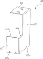
Referring to fig. 1 to 3, a first embodiment of the present invention provides a suckback valve mounting structure 100 comprising: the mounting panel 110, the suck-back valve 10 is arranged on the mounting panel 110; at least one mounting unit 120, the mounting unit 120 being provided to the mounting panel 110 for mounting the suckback valve 10, the mounting unit 120 comprising: the first limiting member 130, the first limiting member 130 is disposed on the mounting panel 110 and limited on the first side surface 11 of the suck-back valve 10; the second limiting piece 140 is arranged on the mounting panel 110, and is limited on the second side surface 12 of the suck-back valve 10, and the plane where the first side surface 11 is located is intersected with the plane where the second side surface 12 is located; the cover plate assembly 150, the cover plate assembly 150 covers the top of the suck back valve 10, the cover plate assembly 150 is detachably connected to at least one of the first retaining member 130, the second retaining member 140 and the mounting panel 110, and the cover plate assembly 150 presses the suck back valve 10 against the mounting panel 110.
In this embodiment, the first limiting member 130 and the second limiting member 140 can limit the horizontal position of the suckback valve 10, so as to prevent the suckback valve 10 from being loosened laterally, and further improve the stability of the pipeline connected to the suckback valve 10; the first limiting member 130 and the second limiting member 140 are pre-installed on the installation panel 110 to form an installation space for accommodating the suck-back valve 10, and after the suck-back valve 10 is installed in the installation space, the cover plate assembly 150 compresses the suck-back valve 10, thereby further improving the stability of the suck-back valve 10. The cover plate assembly 150 may be connected to the first limiting member 130, the second limiting member 140, or the mounting panel 110, and when the suck-back valve 10 is disassembled, the cover plate assembly 150 is only required to be loosened from the connection with other components, and the cover plate assembly 150 is removed, so that the suck-back valve 10 can be disassembled and replaced, and when the suck-back valve 10 is re-assembled, the cover plate assembly 150 and the replaced suck-back valve 10 are only required to be compressed and fixed again, thereby improving the disassembling and assembling efficiency of the suck-back valve 10, and facilitating the maintenance and replacement of the suck-back valve 10.
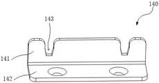
In one particular embodiment, the cover plate assembly 150 includes, for example: the cover plate 151, the cover plate 151 connects the top of the suck-back valve 10 removably; the first baffle 152 is disposed on the first side surface 11, the first baffle 152 is detachably connected to the first limiting member 130, the second baffle 153 is disposed on the second side surface 12, and the second baffle 153 is detachably connected to the second limiting member 140.
It should be noted that the first baffle 152 is used for further limiting the first side surface 11 of the suck-back valve 10, after the first baffle 152 is arranged, the longitudinal dimension of the first limiting member 130 does not need to be too high, and the first side surface 11 can be stably limited after the first limiting member 130 is connected with the first baffle 152; meanwhile, when the first limiting member 130 is connected to the first blocking plate 152, the suck back valve 10 does not need to be directly connected to the first limiting member 130, so that the first side surface 11 does not need to be perforated, grooved or otherwise processed, thereby facilitating installation of the suck back valve 10.
Similarly, the second baffle 153 is used for further limiting the second side surface 12 of the suck-back valve 10, after the second baffle 153 is arranged, the longitudinal dimension of the second limiting member 140 does not need to be too high, and the second limiting member 140 and the second baffle 153 are connected to stably limit the second side surface 12; the second side 12 of the suck back valve 10 does not need to be perforated, grooved or otherwise machined to directly connect to the second retaining member 140, thereby facilitating installation of the suck back valve 10. The second baffle 153 further functions as a limit on the basis that the cover plate assembly 150 has the first baffle 152.
Preferably, a plurality of waist holes may be formed on the cover plate 151, so that the cover plate 151 may be detachably connected to the suck-back valve 10 by fasteners such as screws.
In a specific embodiment, referring to fig. 4, the first barrier 152 and the second barrier 153 are connected to each other, and at least one of the first barrier 152 and the second barrier 153 is connected to the cap plate 151; alternatively, the first barrier 152 and the second barrier 153 are separated, and both the first barrier 152 and the second barrier 153 are connected to the cap plate 151.
It should be noted that, after the cover plate 151 is connected to at least one of the first baffle 152 and the second baffle 153, the simultaneous assembly and disassembly can be realized, and the assembly and disassembly efficiency is improved; after the first baffle 152 is connected to the first limiting member 130 and the second baffle 153 is connected to the second limiting member 140, the horizontal position of the cover plate 151 is fixed; at this time, the first barrier 152 and the second barrier 153 are connected to each other, thereby further improving the stability of the cap plate 151.
In one particular embodiment, the suckback valve 10 comprises, for example: the electronic control device 13, the cable 14 and the first interface 15, wherein the cable 14 and the first interface 15 are positioned at the side of the electronic control device 13. For example, the first interface 15 is located on a side surface of the electronic control device 13 near the top, and the first interfaces 15 are disposed on two opposite sides of the electronic control device 13; the cable 14 is located below any one of the first ports 15 and is connected to the electronic control device 13.
Further, first baffle 152 is located the opposite side of electrically controlled device 13 relative cable 14, and the opposite side of electrically controlled device 13 relative cable 14 is first side 11 promptly, and first baffle 152 includes first dodge position 152b, and first dodge position 152b is located the top of first baffle 152 for dodge first interface 15, be convenient for first interface 15 stretch out and be connected with the pipeline that corresponds, simultaneously, in the process that first interface 15 is connected or is split with the pipeline that corresponds, first dodge position 152b can provide bigger operating space.
It should be noted that, after the first baffle 152 limits the first side surface 11 of the suckback valve 10, the position of the suckback valve 10 in the direction perpendicular to the first baffle 152 is determined, and as long as the cover plate 151 presses the suckback valve 10, the other side surface of the suckback valve 10 opposite to the first side surface 11 does not need to be limited; while the side of the suck back valve 10 away from the cable 14 provides a larger contact area for the first stop 152 to limit.
In a particular embodiment, the suckback valve 10, for example, further comprises: the valve body 16 and the second interface 17, the second interface 17 is positioned at two opposite sides of the valve body 16; the second baffle 153 is located at a side adjacent to the second port 17, that is, any side of the valve body 16 adjacent to the second port 17 can be used as the second side 12, so that the second baffle 153 can limit the position. Wherein, the valve body 16 is located at the top of the electric control device 13, and the second baffle 153 can limit the valve body 16 and the electric control device 13 simultaneously in a direction perpendicular to the first baffle 152, so as to further improve the stability of the suck-back valve 10.
Further, the second baffle 153 includes a second avoidance portion 153b for avoiding the second interface 17, and the second interfaces 17 are located at two sides of the second baffle 153 and correspond to the two second interfaces 17. When the second interface 17 and the corresponding pipeline are disassembled and assembled, the second interface 17 can provide a larger operation space.
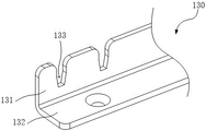
In a specific embodiment, the first limiting member 130 includes, for example: a first limiting plate 131 and a first fixing plate 132, wherein the first limiting plate 131 faces the first side 11, and the first fixing plate 132 is connected to the mounting panel 110; and/or, the second limiting member 140 includes: a second limit plate 141 and a second fixing plate 142, the second limit plate 141 facing the second side 12, and the second fixing plate 142 being connected to the mounting panel 110.
It should be noted that the first fixing plate 132 is used for fixing the first limiting member 130 to the mounting panel 110, and the second fixing plate 142 is used for fixing the second limiting member 140 to the mounting panel 110; a side of the first stopper plate 131 away from the first fixing plate 132 and a side of the second stopper plate 141 away from the second fixing plate 142 form the installation space for accommodating the suckback valve 10; in the assembling and disassembling process of the suckback valve 10, the suckback valve 10 can be taken and placed by vertically moving along the first limiting plate 131 and the second limiting plate 141, and the first limiting member 130 and the second limiting member 140 do not need to be taken down, so the assembly and disassembly are convenient.
Preferably, in conjunction with fig. 4 to 6, the first stopper plate 131 includes, for example, a first fixing hole 133, the first blocking plate 152 includes a first through hole 152a, and the first fixing hole 133 and the first through hole 152a are connected by a first fastener; and/or the second limiting plate 141 includes a second fixing hole 143, the second blocking plate 153 includes a second through hole 153a, and the second fixing hole 143 and the second through hole 153a are connected by a second fastener. The first fixing hole 133 and the first through hole 152a realize quick fixing of the first baffle 152 and the first limiting plate 131; the second fixing holes 143 and the second through holes 153a achieve quick fixing of the second barrier 153 and the second stopper plate 141, and ensure that the first barrier 152 and the second barrier 153 are both in a vertical state.
For example, the first and second fasteners are, for example, pan head screws.
Further, the first fixing hole 133 and the second fixing hole 143 are each provided with an opening vertically upward. Before the suck-back valve 10 is disassembled, the first fastening member and the second fastening member are not required to be removed, the first fastening member and the second fastening member are in a loosened state, the cover plate 151, the first blocking plate 152 and the second blocking plate 153 can be upwardly taken out, and the first fastening member and the second fastening member move upwardly along with the first fastening member and the second fastening member to be separated from the first fastening hole 133 and the second fastening hole 143 through the opening.
Further, the widths of the first fixing hole 133 and the second fixing hole 143 are gradually reduced from the outside of the opening to the inside of the opening, the width of the inside of the first fixing hole 133 and the second fixing hole 143 can realize the clamping effect of the opening on the first fastening piece or the second fastening piece, so that after the cover plate 151 is locked with the top of the suck-back valve 10, the first fastening piece can be pressed against the first fixing hole 133, and the second fastening piece can be pressed against the second fixing hole 143, thereby avoiding the looseness of the first fastening piece and the second fastening piece.
Further, the first fixing hole 133 and the second fixing hole 143 are provided with a guide surface at the opening to facilitate the first fastening member and the second fastening member to slide into the opening, and the guide surface may be an arc surface or an inclined surface, which is not limited herein.
Referring to fig. 1 and 7, the plurality of mounting units 120 are arranged along the length direction of the first limiting member 130 to form a row of mounting modules 101, and the plurality of mounting units 120 of the same mounting module 101 share the same first limiting member 130, so that the plurality of mounting units 120 of the same mounting module 101 are more orderly arranged in the length direction of the first limiting member 130, and a plurality of rows of mounting modules 101 are conveniently arranged.
Preferably, a first accommodating space 160 is formed between adjacent installation units 120 in the installation module 101, and the installation units 120 of adjacent installation modules 101 are arranged in a staggered manner, so that the cables 14 of adjacent installation modules 101 can extend into the first accommodating space 160, the space utilization rate is improved, and meanwhile, the cables 14 are prevented from interfering with other installation units 120, and the cables 14 are prevented from being excessively bent.
[ second embodiment ]
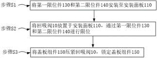
Referring to fig. 8, the present invention further provides a method for installing a suckback valve 10, which is implemented by the suckback valve installation structure 100 provided in any of the above embodiments, where the method for installing the suckback valve 10 includes:
step S1: mounting the first and second stoppers 130 and 140 to the mounting panel 110;
step S2: the suck-back valve 10 is placed on the installation panel 110, and is limited by the first limiting member 130 and the second limiting member 140;
step S3: compressing the cover plate assembly 150 back into the suction valve 10 locks the cover plate assembly 150.
In step S1, a plurality of positioning holes (not shown) for installing the first limiting member 130 and the second limiting member 140 may be disposed on the installation panel 110, and a plurality of installation spaces are formed after the plurality of first limiting members 130 and the plurality of second limiting members 140 are connected to the corresponding positioning holes; in step S2, the suckback valve 10 is placed in the installation space, thereby achieving the limit; in step S3, when the cover plate assembly 150 presses the suckback valve 10, the first fastening member is snapped into the first fastening hole 133, and the second fastening member is snapped into the second fastening hole 143, at which time the cover plate 151 and the top of the suckback valve 10 are fastened by screws, so as to fix the suckback valve 10.
Accordingly, when the suckback valve 10 is disassembled, the suckback valve 10 can be disassembled by loosening and taking down the cover plate assembly 150, so that the disassembly efficiency is high.
Finally, it should be noted that: the above examples are only intended to illustrate the technical solution of the present invention, but not to limit it; although the present invention has been described in detail with reference to the foregoing embodiments, it will be understood by those of ordinary skill in the art that: the technical solutions described in the foregoing embodiments may still be modified, or some technical features may be equivalently replaced; and such modifications or substitutions do not depart from the spirit and scope of the corresponding technical solutions of the embodiments of the present invention.
Claims (10)
1. A suckback valve mounting structure, comprising:
the back suction valve is arranged on the mounting panel;
at least one mounting unit, the mounting unit is located the mounting panel for install the suckback valve, the mounting unit includes:
the first limiting piece is arranged on the mounting panel and limited on the first side surface of the suck-back valve;
the second limiting piece is arranged on the mounting panel and limited on a second side surface of the suck-back valve, and a plane where the first side surface is located is crossed with a plane where the second side surface is located;
the cover plate assembly covers the top of the suckback valve, the cover plate assembly is detachably connected with at least one of the first limiting part, the second limiting part and the installation panel, and the suckback valve is pressed on the installation panel through the cover plate assembly.
2. The suckback valve mounting structure of claim 1, wherein the cover plate assembly comprises:
the cover plate is detachably connected with the top of the suckback valve;
the first baffle is arranged on a first side face, the first baffle is detachably connected with the first limiting piece, the second baffle is arranged on a second side face, and the second baffle is detachably connected with the second limiting piece.
3. The suckback valve mounting structure of claim 2, wherein the first baffle and the second baffle are connected to each other, and at least one of the first baffle and the second baffle is connected to the cover plate;
or the first baffle plate and the second baffle plate are separated, and the first baffle plate and the second baffle plate are both connected with the cover plate.
4. The suckback valve mounting structure according to any one of claims 2 to 3, wherein the suckback valve comprises: the device comprises an electric control device, a cable and a first interface, wherein the cable and the first interface are positioned on the side surface of the electric control device;
the first baffle is located on the other side, opposite to the cable, of the electric control device, and the first baffle comprises a first avoidance position, and the first avoidance position is used for avoiding the first interface.
5. The suckback valve mounting structure according to any one of claims 2 to 3, wherein the suckback valve comprises: the valve comprises a valve body and second interfaces, wherein the second interfaces are positioned on two opposite sides of the valve body;
the second baffle is located on one side adjacent to the second interface and comprises a second avoidance position used for avoiding the second interface.
6. The suckback valve mounting structure of any one of claims 2-3, wherein the first retaining member comprises: the first limiting plate faces the first side face, and the first fixing plate is connected with the mounting panel;
and/or, the second limiting member comprises: the second limiting plate faces the second side face, and the second fixing plate is connected with the mounting panel.
7. The suckback valve mounting structure of claim 6, wherein the first retainer plate comprises a first fixing hole, the first baffle comprises a first through hole, and the first fixing hole and the first through hole are connected by a first fastener;
and/or, the second limiting plate comprises a second fixing hole, the second baffle plate comprises a second through hole, and the second fixing hole is connected with the second through hole through a second fastener.
8. The suckback valve mounting structure according to claim 7, wherein the first fixing hole and the second fixing hole are each provided with an opening that is directed vertically upward.
9. The suckback valve installation structure of claim 1, wherein a plurality of said installation units are arranged along the length direction of said first retainer to form a row of installation modules, and a first receiving space is formed between adjacent installation units in said row of installation modules.
10. A suckback valve mounting method achieved by the suckback valve mounting structure according to any one of claims 1 to 9, wherein the suckback valve mounting method comprises:
mounting the first and second stoppers to the mounting panel;
placing the suck-back valve on the installation panel, and limiting through the first limiting piece and the second limiting piece;
and pressing the cover plate assembly against the suck-back valve to lock the cover plate assembly.
Priority Applications (1)
| Application Number | Priority Date | Filing Date | Title |
|---|---|---|---|
| CN202210370926.4A CN114460812B (en) | 2022-04-11 | 2022-04-11 | Structure and method for mounting suck-back valve |
Applications Claiming Priority (1)
| Application Number | Priority Date | Filing Date | Title |
|---|---|---|---|
| CN202210370926.4A CN114460812B (en) | 2022-04-11 | 2022-04-11 | Structure and method for mounting suck-back valve |
Publications (2)
| Publication Number | Publication Date |
|---|---|
| CN114460812A true CN114460812A (en) | 2022-05-10 |
| CN114460812B CN114460812B (en) | 2022-08-05 |
Family
ID=81417539
Family Applications (1)
| Application Number | Title | Priority Date | Filing Date |
|---|---|---|---|
| CN202210370926.4A Active CN114460812B (en) | 2022-04-11 | 2022-04-11 | Structure and method for mounting suck-back valve |
Country Status (1)
| Country | Link |
|---|---|
| CN (1) | CN114460812B (en) |
Citations (10)
| Publication number | Priority date | Publication date | Assignee | Title |
|---|---|---|---|---|
| JPH0262031A (en) * | 1988-08-27 | 1990-03-01 | Nec Corp | Suck-back valve |
| CN102622060A (en) * | 2012-02-23 | 2012-08-01 | 苏州佳世达电通有限公司 | Fixing device and electronic equipment |
| CN204359674U (en) * | 2015-01-26 | 2015-05-27 | 苏州矩度电子科技有限公司 | The camera adjustments device of optical detection apparatus |
| CN204538511U (en) * | 2015-05-11 | 2015-08-05 | 华自科技股份有限公司 | A kind of distribution box mounting bracket |
| CN205536420U (en) * | 2016-01-21 | 2016-08-31 | 珠海格力电器股份有限公司 | Grafting structure, grafting coupling assembling and air conditioning unit |
| CN106238212A (en) * | 2016-08-30 | 2016-12-21 | 陕西建工安装集团有限公司 | A kind of cathode line jig and cathode line location adjust construction method |
| CN210270724U (en) * | 2019-08-19 | 2020-04-07 | 李延宁 | Fixed mounting device of computer motherboard |
| CN212130971U (en) * | 2019-12-24 | 2020-12-11 | 瑞声科技(新加坡)有限公司 | Fixing assembly and electronic feedback device |
| CN215171269U (en) * | 2020-08-28 | 2021-12-14 | 东土科技(宜昌)有限公司 | Rail clamping seat and equipment |
| CN114226092A (en) * | 2021-12-16 | 2022-03-25 | 蒋恒 | Glue coating device and using method thereof |
-
2022
- 2022-04-11 CN CN202210370926.4A patent/CN114460812B/en active Active
Patent Citations (10)
| Publication number | Priority date | Publication date | Assignee | Title |
|---|---|---|---|---|
| JPH0262031A (en) * | 1988-08-27 | 1990-03-01 | Nec Corp | Suck-back valve |
| CN102622060A (en) * | 2012-02-23 | 2012-08-01 | 苏州佳世达电通有限公司 | Fixing device and electronic equipment |
| CN204359674U (en) * | 2015-01-26 | 2015-05-27 | 苏州矩度电子科技有限公司 | The camera adjustments device of optical detection apparatus |
| CN204538511U (en) * | 2015-05-11 | 2015-08-05 | 华自科技股份有限公司 | A kind of distribution box mounting bracket |
| CN205536420U (en) * | 2016-01-21 | 2016-08-31 | 珠海格力电器股份有限公司 | Grafting structure, grafting coupling assembling and air conditioning unit |
| CN106238212A (en) * | 2016-08-30 | 2016-12-21 | 陕西建工安装集团有限公司 | A kind of cathode line jig and cathode line location adjust construction method |
| CN210270724U (en) * | 2019-08-19 | 2020-04-07 | 李延宁 | Fixed mounting device of computer motherboard |
| CN212130971U (en) * | 2019-12-24 | 2020-12-11 | 瑞声科技(新加坡)有限公司 | Fixing assembly and electronic feedback device |
| CN215171269U (en) * | 2020-08-28 | 2021-12-14 | 东土科技(宜昌)有限公司 | Rail clamping seat and equipment |
| CN114226092A (en) * | 2021-12-16 | 2022-03-25 | 蒋恒 | Glue coating device and using method thereof |
Also Published As
| Publication number | Publication date |
|---|---|
| CN114460812B (en) | 2022-08-05 |
Similar Documents
| Publication | Publication Date | Title |
|---|---|---|
| US6874538B2 (en) | Fluid delivery system | |
| US7515413B1 (en) | Fan field replaceable unit | |
| US6513770B1 (en) | Electronic device support and method | |
| US7455735B2 (en) | Width adjustable substrate support for plasma processing | |
| CN114460812B (en) | Structure and method for mounting suck-back valve | |
| US7819693B2 (en) | LGA socket having improved standoff | |
| WO2013071644A1 (en) | Locking accessory, backlight module and liquid crystal display device | |
| US20110045691A1 (en) | Easily installable network wiring device | |
| CN211667910U (en) | Air conditioner purification assembly and air conditioner assembly | |
| CN115719894A (en) | Electric connection device, manufacturing method and computer equipment | |
| CN217539782U (en) | Valve mounting structure | |
| CN213692656U (en) | Integrated electronic control board with mounting structure | |
| CN217115869U (en) | Matrix motor controller structure | |
| CN211606817U (en) | Interactive 4G industry thing networking gateway equipment | |
| CN220348767U (en) | Adsorption equipment and processing equipment | |
| CN217984253U (en) | Drawer seat of circuit breaker | |
| CN219917782U (en) | Power connector assembly of cabinet bus | |
| CN211888349U (en) | Integrated circuit module structure of cleaning machine | |
| CN111524776B (en) | Front-end module, control method thereof and semiconductor processing equipment | |
| CN219889481U (en) | Connection structure of track combination lamp | |
| CN217173936U (en) | Manual liquid level regulating assembly | |
| CN214038664U (en) | Fresh air base and air conditioner | |
| CN210215541U (en) | Film deposition equipment | |
| CN210053413U (en) | Intelligent gateway | |
| JP4644473B2 (en) | Partial plating equipment |
Legal Events
| Date | Code | Title | Description |
|---|---|---|---|
| PB01 | Publication | ||
| PB01 | Publication | ||
| SE01 | Entry into force of request for substantive examination | ||
| SE01 | Entry into force of request for substantive examination | ||
| GR01 | Patent grant | ||
| GR01 | Patent grant |