CN114435913B - Automatic attaching equipment of multifunctional camera assembly - Google Patents
Automatic attaching equipment of multifunctional camera assembly Download PDFInfo
- Publication number
- CN114435913B CN114435913B CN202210206017.7A CN202210206017A CN114435913B CN 114435913 B CN114435913 B CN 114435913B CN 202210206017 A CN202210206017 A CN 202210206017A CN 114435913 B CN114435913 B CN 114435913B
- Authority
- CN
- China
- Prior art keywords
- axis direction
- control
- conveying
- control mechanism
- move
- Prior art date
- Legal status (The legal status is an assumption and is not a legal conclusion. Google has not performed a legal analysis and makes no representation as to the accuracy of the status listed.)
- Active
Links
- 230000007246 mechanism Effects 0.000 claims abstract description 630
- 239000000463 material Substances 0.000 claims abstract description 209
- 238000012546 transfer Methods 0.000 claims abstract description 91
- 230000003287 optical effect Effects 0.000 claims abstract description 30
- 238000012360 testing method Methods 0.000 claims abstract description 30
- 239000003292 glue Substances 0.000 claims abstract description 28
- 238000001514 detection method Methods 0.000 claims abstract description 26
- 238000007599 discharging Methods 0.000 claims abstract description 24
- 230000033001 locomotion Effects 0.000 claims description 38
- 230000007306 turnover Effects 0.000 claims description 17
- 230000003028 elevating effect Effects 0.000 claims description 14
- 238000010030 laminating Methods 0.000 claims description 14
- 230000005540 biological transmission Effects 0.000 claims description 8
- 238000010438 heat treatment Methods 0.000 claims description 6
- 230000000149 penetrating effect Effects 0.000 claims description 2
- 238000004519 manufacturing process Methods 0.000 abstract description 20
- 238000007689 inspection Methods 0.000 abstract 1
- 210000000078 claw Anatomy 0.000 description 21
- 238000010586 diagram Methods 0.000 description 18
- 230000007723 transport mechanism Effects 0.000 description 14
- 230000009467 reduction Effects 0.000 description 6
- 230000001360 synchronised effect Effects 0.000 description 6
- 238000001179 sorption measurement Methods 0.000 description 5
- 239000000725 suspension Substances 0.000 description 5
- 230000006698 induction Effects 0.000 description 4
- 230000001681 protective effect Effects 0.000 description 4
- 230000009471 action Effects 0.000 description 3
- 239000000853 adhesive Substances 0.000 description 3
- 230000001070 adhesive effect Effects 0.000 description 3
- 230000007547 defect Effects 0.000 description 3
- 238000005259 measurement Methods 0.000 description 3
- 238000000034 method Methods 0.000 description 3
- 230000008569 process Effects 0.000 description 3
- 230000006641 stabilisation Effects 0.000 description 3
- 238000011105 stabilization Methods 0.000 description 3
- 230000000712 assembly Effects 0.000 description 2
- 238000000429 assembly Methods 0.000 description 2
- 238000012840 feeding operation Methods 0.000 description 2
- 238000004806 packaging method and process Methods 0.000 description 2
- 229910001220 stainless steel Inorganic materials 0.000 description 2
- 239000010935 stainless steel Substances 0.000 description 2
- XAGFODPZIPBFFR-UHFFFAOYSA-N aluminium Chemical compound [Al] XAGFODPZIPBFFR-UHFFFAOYSA-N 0.000 description 1
- 229910052782 aluminium Inorganic materials 0.000 description 1
- 239000011324 bead Substances 0.000 description 1
- 238000011109 contamination Methods 0.000 description 1
- 238000013461 design Methods 0.000 description 1
- 239000012769 display material Substances 0.000 description 1
- 230000000763 evoking effect Effects 0.000 description 1
- 230000003993 interaction Effects 0.000 description 1
- 239000012528 membrane Substances 0.000 description 1
- 238000012986 modification Methods 0.000 description 1
- 230000004048 modification Effects 0.000 description 1
- 230000002093 peripheral effect Effects 0.000 description 1
- 238000012545 processing Methods 0.000 description 1
- 230000002441 reversible effect Effects 0.000 description 1
- 238000007711 solidification Methods 0.000 description 1
- 230000008023 solidification Effects 0.000 description 1
Images


Classifications
-
- B—PERFORMING OPERATIONS; TRANSPORTING
- B65—CONVEYING; PACKING; STORING; HANDLING THIN OR FILAMENTARY MATERIAL
- B65G—TRANSPORT OR STORAGE DEVICES, e.g. CONVEYORS FOR LOADING OR TIPPING, SHOP CONVEYOR SYSTEMS OR PNEUMATIC TUBE CONVEYORS
- B65G47/00—Article or material-handling devices associated with conveyors; Methods employing such devices
- B65G47/22—Devices influencing the relative position or the attitude of articles during transit by conveyors
- B65G47/24—Devices influencing the relative position or the attitude of articles during transit by conveyors orientating the articles
- B65G47/248—Devices influencing the relative position or the attitude of articles during transit by conveyors orientating the articles by turning over or inverting them
-
- B—PERFORMING OPERATIONS; TRANSPORTING
- B65—CONVEYING; PACKING; STORING; HANDLING THIN OR FILAMENTARY MATERIAL
- B65G—TRANSPORT OR STORAGE DEVICES, e.g. CONVEYORS FOR LOADING OR TIPPING, SHOP CONVEYOR SYSTEMS OR PNEUMATIC TUBE CONVEYORS
- B65G37/00—Combinations of mechanical conveyors of the same kind, or of different kinds, of interest apart from their application in particular machines or use in particular manufacturing processes
-
- B—PERFORMING OPERATIONS; TRANSPORTING
- B65—CONVEYING; PACKING; STORING; HANDLING THIN OR FILAMENTARY MATERIAL
- B65G—TRANSPORT OR STORAGE DEVICES, e.g. CONVEYORS FOR LOADING OR TIPPING, SHOP CONVEYOR SYSTEMS OR PNEUMATIC TUBE CONVEYORS
- B65G41/00—Supporting frames or bases for conveyors as a whole, e.g. transportable conveyor frames
- B65G41/001—Supporting frames or bases for conveyors as a whole, e.g. transportable conveyor frames with the conveyor adjustably mounted on the supporting frame or base
- B65G41/003—Supporting frames or bases for conveyors as a whole, e.g. transportable conveyor frames with the conveyor adjustably mounted on the supporting frame or base mounted for linear movement only
-
- B—PERFORMING OPERATIONS; TRANSPORTING
- B65—CONVEYING; PACKING; STORING; HANDLING THIN OR FILAMENTARY MATERIAL
- B65G—TRANSPORT OR STORAGE DEVICES, e.g. CONVEYORS FOR LOADING OR TIPPING, SHOP CONVEYOR SYSTEMS OR PNEUMATIC TUBE CONVEYORS
- B65G43/00—Control devices, e.g. for safety, warning or fault-correcting
- B65G43/08—Control devices operated by article or material being fed, conveyed or discharged
-
- B—PERFORMING OPERATIONS; TRANSPORTING
- B65—CONVEYING; PACKING; STORING; HANDLING THIN OR FILAMENTARY MATERIAL
- B65G—TRANSPORT OR STORAGE DEVICES, e.g. CONVEYORS FOR LOADING OR TIPPING, SHOP CONVEYOR SYSTEMS OR PNEUMATIC TUBE CONVEYORS
- B65G47/00—Article or material-handling devices associated with conveyors; Methods employing such devices
- B65G47/74—Feeding, transfer, or discharging devices of particular kinds or types
- B65G47/90—Devices for picking-up and depositing articles or materials
- B65G47/901—Devices for picking-up and depositing articles or materials provided with drive systems with rectilinear movements only
-
- B—PERFORMING OPERATIONS; TRANSPORTING
- B65—CONVEYING; PACKING; STORING; HANDLING THIN OR FILAMENTARY MATERIAL
- B65G—TRANSPORT OR STORAGE DEVICES, e.g. CONVEYORS FOR LOADING OR TIPPING, SHOP CONVEYOR SYSTEMS OR PNEUMATIC TUBE CONVEYORS
- B65G47/00—Article or material-handling devices associated with conveyors; Methods employing such devices
- B65G47/74—Feeding, transfer, or discharging devices of particular kinds or types
- B65G47/90—Devices for picking-up and depositing articles or materials
- B65G47/91—Devices for picking-up and depositing articles or materials incorporating pneumatic, e.g. suction, grippers
- B65G47/914—Devices for picking-up and depositing articles or materials incorporating pneumatic, e.g. suction, grippers provided with drive systems incorporating rotary and rectilinear movements
-
- F—MECHANICAL ENGINEERING; LIGHTING; HEATING; WEAPONS; BLASTING
- F16—ENGINEERING ELEMENTS AND UNITS; GENERAL MEASURES FOR PRODUCING AND MAINTAINING EFFECTIVE FUNCTIONING OF MACHINES OR INSTALLATIONS; THERMAL INSULATION IN GENERAL
- F16B—DEVICES FOR FASTENING OR SECURING CONSTRUCTIONAL ELEMENTS OR MACHINE PARTS TOGETHER, e.g. NAILS, BOLTS, CIRCLIPS, CLAMPS, CLIPS OR WEDGES; JOINTS OR JOINTING
- F16B11/00—Connecting constructional elements or machine parts by sticking or pressing them together, e.g. cold pressure welding
- F16B11/006—Connecting constructional elements or machine parts by sticking or pressing them together, e.g. cold pressure welding by gluing
-
- H—ELECTRICITY
- H04—ELECTRIC COMMUNICATION TECHNIQUE
- H04N—PICTORIAL COMMUNICATION, e.g. TELEVISION
- H04N23/00—Cameras or camera modules comprising electronic image sensors; Control thereof
Landscapes
- Engineering & Computer Science (AREA)
- Mechanical Engineering (AREA)
- General Engineering & Computer Science (AREA)
- Multimedia (AREA)
- Signal Processing (AREA)
- Investigating Materials By The Use Of Optical Means Adapted For Particular Applications (AREA)
- Container, Conveyance, Adherence, Positioning, Of Wafer (AREA)
Abstract
The invention provides automatic attaching equipment for a multifunctional camera assembly, which comprises a rotatable overturning feeding and discharging device, an optical testing device, a glue dispensing device, a high-precision attaching device, an ultraviolet lamp and a material conveying mechanism, wherein the rotatable overturning feeding and discharging device, the optical testing device, the glue dispensing device, the high-precision attaching device and the ultraviolet lamp are sequentially arranged side by side in the X-axis direction, the ultraviolet lamp is positioned above the material conveying mechanism in the Z-axis direction, the rotatable overturning feeding and discharging device comprises a rotatable overturning mechanism, a transfer mechanism and a feeding and discharging mechanism, the optical testing device comprises an AOI (automatic optical inspection) camera and a testing control mechanism, the glue dispensing device comprises a glue dispenser and a glue dispensing control mechanism, and the high-precision attaching device comprises an attaching mechanism, a quality detection mechanism and a material taking mechanism. The multifunctional camera component automatic attaching equipment has the advantages of high automation degree, strong universality, stable and reliable work, simple and compact structure, and capability of reducing the occupied space of production operation and reducing the production cost of enterprises.
Description
Technical Field
The invention relates to the technical field of automatic production equipment, in particular to automatic attaching equipment for a multifunctional camera assembly.
Background
In camera subassembly production assembling process, often can bond through point gum between two spare parts of camera subassembly and fix an organic whole with attached process, for example the IR piece (light filter) of camera is attached, the prism of camera is attached, the mirror (the reflector) of camera is attached, the aluminum sheet of camera is attached, the module support of camera is attached, the PCB subassembly of camera is attached etc.. Because the attachment surfaces of two parts of different camera assemblies are different, the related parts need to be rotated or turned over by different angles before assembly.
In order to guarantee automatic production efficiency, the existing operation mode is that a multi-axis industrial robot is utilized to rotate or overturn related parts of different camera assemblies at different angles, but the movement stroke of each joint arm of the multi-axis industrial robot is large, so that the operation occupied space of equipment is large, the price of the multi-axis industrial robot is generally high, and further the production cost is increased.
In addition, another operation mode is to design different automatic attached equipment to different camera subassemblies now, greatly increased enterprise's manufacturing cost to greatly increased enterprise's production operation occupation space.
Disclosure of Invention
The invention mainly aims to provide the automatic attaching equipment for the multifunctional camera component, which has the advantages of high automation degree, strong universality, stable and reliable work, simple and compact structure, reduction of occupied space of production operation and reduction of production cost of enterprises.
In order to realize the main purpose of the invention, the invention provides automatic attaching equipment of a multifunctional camera component, which comprises a rotatable overturning feeding and discharging device, an optical testing device, a dispensing device, a high-precision attaching device, an ultraviolet lamp and a material conveying mechanism, wherein the rotatable overturning feeding and discharging device, the optical testing device, the dispensing device, the high-precision attaching device and the ultraviolet lamp are sequentially arranged side by side in the X-axis direction, the material conveying mechanism is used for conveying materials in the X-axis direction, the ultraviolet lamp is positioned above the material conveying mechanism in the Z-axis direction, the rotatable overturning feeding and discharging device comprises a rotatable overturning mechanism, a transfer mechanism and a feeding and discharging mechanism, the rotatable overturning mechanism, the transfer mechanism and the feeding and discharging mechanism are sequentially arranged side by side in the Y-axis direction, the feeding and discharging mechanism is positioned above the material conveying mechanism in the Z-axis direction, the rotary overturning mechanism comprises a moving driving mechanism, a first moving plate, a rotation control mechanism, an overturning control mechanism, a nozzle seat and a first vacuum nozzle, the moving driving mechanism can control the first moving plate to move in the Y-axis direction and the Z-axis direction respectively, the overturning control mechanism is arranged on the first moving plate and can control the nozzle seat to rotate around the X-axis direction, the rotation control mechanism and the first vacuum nozzle are arranged on the nozzle seat respectively, the rotation control mechanism can control the first vacuum nozzle to rotate around the axis of the rotation control mechanism, the transfer mechanism comprises a transfer table and a lifting driving mechanism, the lifting driving mechanism can control the transfer table to move in the Z-axis direction, the feeding and discharging mechanism comprises a moving driving mechanism and a first moving plate, the moving driving mechanism can control the first moving plate to move in the Y-axis direction and the Z-axis direction respectively, the first moving plate is provided with a second vacuum nozzle or a vacuum suction disc, the optical testing device comprises an AOI camera and a testing control mechanism, wherein the AOI camera is positioned above the material conveying mechanism in the Z-axis direction, the testing control mechanism can control the AOI camera to move in the Z-axis direction and the Y-axis direction respectively, the glue dispensing device comprises a glue dispenser and a glue dispensing control mechanism, the glue dispenser is positioned above the material conveying mechanism in the Z-axis direction, the glue dispensing control mechanism can control the glue dispenser to move in the Z-axis direction and the Y-axis direction respectively, the high-precision laminating device comprises an attaching mechanism, a quality detecting mechanism and a material taking mechanism, the quality detecting mechanism is positioned between the attaching mechanism and the material taking mechanism in the Y-axis direction, the quality detecting mechanism comprises a rotation control mechanism, a rotating disk and an AOI optical detector, the rotation control mechanism can control the rotation disk to rotate around the Z axis, the rotating disk is provided with a plurality of through grooves, the plurality of through grooves are uniformly distributed around the rotating shaft of the rotating disc and penetrate through the rotating disc in the Z-axis direction, the AOI optical detector is positioned below the rotating disc in the Z-axis direction and is arranged opposite to the through grooves, the material taking mechanism comprises a transfer control mechanism, a first transfer seat and a first vacuum material taking nozzle, the transfer control mechanism can control the first transfer seat to move in the X-axis direction, the Y-axis direction and the Z-axis direction respectively, the first vacuum material taking nozzle is arranged on the first transfer seat, the attaching mechanism comprises a carrying control mechanism, a first carrying seat, a second vacuum material taking nozzle and two UV exposure lamps, the carrying control mechanism can control the first carrying seat to move in the X-axis direction, the Y-axis direction and the Z-axis direction respectively, the second vacuum material taking nozzle and the two UV exposure lamps are arranged on the first carrying seat respectively, and the two UV exposure lamps are respectively positioned at the periphery of the second vacuum material taking nozzle and are obliquely arranged towards the second vacuum material taking nozzle.
According to the scheme, the automatic attaching equipment for the multifunctional camera component has the advantages of high automation degree, strong universality, stable and reliable work, simple and compact structure, reduction of occupied space of production operation and reduction of production cost of enterprises.
One preferred scheme is that, unloader still includes location detection mechanism in the upset of can revolving, and location detection mechanism lies in one side that unloading mechanism was kept away from to revolving and overturning mechanism on Y axle direction, and location detection mechanism includes location camera, locating plate and location actuating mechanism, and the steerable locating plate of location actuating mechanism moves in Y axle direction, and the location camera setting is on the locating plate.
According to a further scheme, the positioning detection mechanism further comprises a first dimension code scanner, and the first dimension code scanner is arranged on the positioning plate.
According to a further scheme, the rotatable overturning feeding and discharging device further comprises a second dimension code scanner, and the second dimension code scanner is located below the first dimension code scanner in the Z-axis direction.
According to a further scheme, the high-precision laminating device further comprises a first positioning mechanism, the first positioning mechanism is located on one side, away from the material taking mechanism, of the attaching mechanism in the Y-axis direction and located above the material conveying mechanism in the Z-axis direction, the first positioning mechanism comprises a first transfer control mechanism, a first transfer seat and a first camera, the first transfer control mechanism can control the first transfer seat to move in the Y-axis direction and the Z-axis direction respectively, and the first camera is arranged on the first transfer seat; and/or the high-precision laminating device further comprises a second positioning mechanism, the second positioning mechanism is positioned on one side, away from the first positioning mechanism, of the quality detection mechanism in the Y-axis direction, the second positioning mechanism comprises a second transfer control mechanism, a second transfer seat and a second camera, the second transfer control mechanism can control the second transfer seat to move in the Y-axis direction, and the second camera is arranged on the second transfer seat; and/or the high-precision laminating device further comprises a third camera, the third camera is positioned above the rotating disc in the Z-axis direction, and the third camera is positioned on one side, far away from the material taking mechanism, of the rotating disc in the Y-axis direction and is arranged opposite to the through groove; and/or, high accuracy laminating device still includes the fourth camera, and the fourth camera is located the below of rotary disk and is located the rotary disk in the Y axle direction and keep away from one side of extracting mechanism in the Y axle direction on the Z axle direction, and the fourth camera sets up with logical groove is relative.
In a further scheme, a plurality of heating rings are arranged on the end face, close to the AOI optical detector, of the rotating disc in the Z-axis direction, and one heating ring is arranged on the periphery of one through groove in a surrounding mode.
According to a further scheme, the automatic attaching equipment of the multifunctional camera assembly further comprises a wafer feeding device which is arranged close to the taking mechanism, the wafer feeding device comprises a film expanding mechanism and a jacking mechanism, the film expanding mechanism comprises a sliding plate, a sliding control mechanism, a bearing plate, a bearing control mechanism, a baffle plate, a film expanding ring and a rotation control mechanism, the sliding control mechanism can control the sliding plate to move in the X-axis direction, the bearing plate can be movably supported above the sliding plate in the Z-axis direction, the bearing control mechanism can control the bearing plate to move in the Z-axis direction, the bearing plate penetrates through film expanding holes in the Z-axis direction, the baffle plate is arranged on the bearing plate adjacent to the peripheries of the film expanding holes, a limiting gap is formed between the baffle plate and the bearing plate in the Z-axis direction, the film expanding ring can be rotatably supported on the sliding plate in the Z-axis direction, the rotation control mechanism can control the film expanding ring to rotate in the Z-axis direction, film expanding edges of the film expanding ring can be inserted into the film expanding holes, the jacking mechanism comprises a vacuum sleeve, the jacking mechanism can control sleeve movably penetrate out of the top end of the vacuum ring which can be inserted into the top of the vacuum expanding ring, and the multi-axis ring which is movably arranged in the Z-axis moving control sleeve, and the jacking mechanism can control sleeve which can be movably arranged in the top of the jacking sleeve, and the jacking mechanism, and the jacking sleeve which can be inserted into the top of the multi-axis moving sleeve which is arranged in the top of the multi-axis moving control sleeve.
The multifunctional camera assembly automatic attaching equipment further comprises a double-layer conveying line arranged close to the rotary turnover mechanism, the double-layer conveying line comprises a first upper layer conveying mechanism, a first lower layer conveying mechanism and a first motion control mechanism, the first upper layer conveying mechanism is located above the first lower layer conveying mechanism in the Z-axis direction, the first upper layer conveying mechanism comprises a first support frame, a first conveying belt, a second conveying belt and a first transmission control mechanism, the first conveying belt and the second conveying belt extend in the X-axis direction and can be supported on the first support frame in a movable mode in the X-axis direction, the first conveying belt and the second conveying belt are arranged side by side in the Y-axis direction, the first transmission control mechanism can control the first conveying belt and the second conveying belt to move in the X-axis direction synchronously, the first motion control mechanism can control the first support frame to move in the X-axis direction, the first lower layer conveying mechanism comprises a second support frame, a third conveying belt, a fourth conveying belt and a second transmission control mechanism, the third conveying belt and the fourth conveying belt extend in the X-axis direction and can be supported in the third conveying belt and the fourth conveying belt and can be controlled in the X-axis direction synchronously.
A further scheme is that the number of the rotatable turnover loading and unloading devices is two, one rotatable turnover loading and unloading device is positioned on one side of the optical testing device far away from the ultraviolet lamp in the X-axis direction, the other rotatable turnover loading and unloading device is positioned on one side of the ultraviolet lamp far away from the optical testing device in the X-axis direction, the double-layer conveying line further comprises a second upper-layer conveying mechanism and a second motion control mechanism, the second upper-layer conveying mechanism and the first upper-layer conveying mechanism are positioned between the two rotatable turnover loading and unloading devices in the X-axis direction, the second upper-layer conveying mechanism is positioned above the first lower-layer conveying mechanism in the Z-axis direction, the second upper-layer conveying mechanism comprises a fifth supporting frame, a ninth conveying belt, a tenth conveying belt and a fifth transport control mechanism, the ninth conveying belt and the tenth conveying belt extend in the X-axis direction and are movably supported on the fifth supporting frame in the X-axis direction, the ninth conveying belt and the tenth conveying belt are arranged side by side in the Y-axis direction, and the ninth conveying belt and the tenth conveying belt can be synchronously moved in the X-axis direction by the fifth transport control mechanism.
According to a further scheme, the double-layer conveying line further comprises a feeding lifting mechanism, the feeding lifting mechanism is located at the first end of the first lower-layer conveying mechanism in the X-axis direction, the feeding lifting mechanism comprises a third supporting frame, a fifth conveying belt, a sixth conveying belt, a third conveying control mechanism and a first lifting control mechanism, the first lifting control mechanism can control the third supporting frame to move in the Z-axis direction, the fifth conveying belt and the sixth conveying belt extend in the X-axis direction and are movably supported on the third supporting frame in the X-axis direction, the fifth conveying belt and the sixth conveying belt are arranged side by side in the Y-axis direction, and the third conveying control mechanism can control the fifth conveying belt and the sixth conveying belt to synchronously move in the X-axis direction; and/or, double-deck transfer chain still includes unloading elevating system, unloading elevating system is located first lower floor conveying mechanism's second end in X axle direction, unloading elevating system includes the fourth support frame, the seventh conveyer belt, the eighth conveyer belt, fourth conveying control mechanism and second elevating control mechanism, the steerable fourth support frame of second elevating control mechanism removes in Z axle direction, seventh conveyer belt and eighth conveyer belt extend and can support on the fourth support frame with removing in X axle direction on X axle direction, and seventh conveyer belt and eighth conveyer belt set up side by side in Y axle direction, the steerable seventh conveyer belt of fourth conveying control mechanism and eighth conveyer belt remove in X axle direction in step.
Drawings
Fig. 1 is a block diagram of an embodiment of an automated multi-functional camera assembly attaching apparatus according to the present invention.
Fig. 2 is a structural view of a double-layer conveyor line in an embodiment of an automated multi-functional camera assembly attaching apparatus according to the present invention.
Fig. 3 is a first view structural diagram and a second view structural diagram of a feeding lifting mechanism in an embodiment of the multifunctional camera assembly automatic attaching device of the present invention.
Fig. 4 is a first perspective exploded view and a second perspective exploded view of a feeding and lifting mechanism in an embodiment of the multifunctional camera assembly automatic attaching apparatus of the present invention.
Fig. 5 is a first perspective structural view and a second perspective structural view of the cooperation of the first upper layer conveying mechanism and the first lower layer conveying mechanism in the embodiment of the automatic attachment device for the multifunctional camera assembly of the present invention.
Fig. 6 is a structural view of a third upper transport mechanism in an embodiment of the automated multi-functional camera assembly attaching apparatus of the present invention.
Fig. 7 is a first view structural diagram and a second view structural diagram of the cooperation of a second upper layer conveying mechanism and a second lower layer conveying mechanism in the embodiment of the automatic attaching device of the multifunctional camera assembly of the present invention.
Fig. 8 is a structural diagram of a blanking lifting mechanism in an embodiment of the automatic multifunctional camera assembly attaching device of the present invention.
Fig. 9 is an exploded view of a blanking lifting mechanism in an embodiment of the multifunctional camera assembly automatic attaching apparatus of the present invention.
Fig. 10 is a structural diagram of a material pushing mechanism in an embodiment of the automated multifunctional camera assembly attaching apparatus of the present invention.
Fig. 11 is a structural view and a partial structural sectional view of a material transfer mechanism in an embodiment of the automated multi-functional camera assembly attaching apparatus according to the present invention.
Fig. 12 is a structural diagram of a rotatable and reversible loading and unloading device in an embodiment of the multifunctional camera assembly automatic attachment apparatus of the present invention.
Fig. 13 is a structural view of a positioning detection mechanism in an embodiment of the automated multi-functional camera assembly attaching apparatus of the present invention.
Fig. 14 is a first perspective view structural view of a rotation and turnover mechanism in an embodiment of the automated multifunctional camera assembly attaching apparatus of the present invention.
Fig. 15 is a second perspective view structural view of the rotation and inversion mechanism in the embodiment of the automated multifunctional camera assembly attaching apparatus according to the present invention.
Fig. 16 is a first view structural diagram of an embodiment of a loading and unloading mechanism in an embodiment of an automated multifunctional camera assembly attaching apparatus according to the present invention.
Fig. 17 is a second view structural diagram of an embodiment of a loading and unloading mechanism in an embodiment of an automated multifunctional camera assembly attaching apparatus according to the present invention.
Fig. 18 is a structural view of another embodiment of a loading and unloading mechanism in an embodiment of an automated multifunctional camera assembly attaching apparatus according to the present invention.
Fig. 19 is a block diagram of an optical test device in an embodiment of the automated multifunctional camera assembly attaching apparatus of the present invention.
Fig. 20 is a structural diagram of a dispensing device in an embodiment of an automated multi-functional camera assembly attaching apparatus according to the present invention.
Fig. 21 is a structural diagram of a dispensing mechanism in an embodiment of the automated multifunctional camera assembly attaching apparatus of the present invention.
Fig. 22 is a block diagram of a material extracting mechanism in an embodiment of the automatic attaching apparatus for a multifunctional camera assembly according to the present invention.
Fig. 23 is a structural view of a high precision attaching device in an embodiment of the automated attaching apparatus for a multi-functional camera assembly according to the present invention.
Fig. 24 is a structural view of a quality detecting mechanism in an embodiment of the automated multi-function camera module attaching apparatus according to the present invention.
Fig. 25 is a structural view of an attaching mechanism in an embodiment of the automated attaching apparatus for a multi-functional camera assembly according to the present invention.
Fig. 26 is a partial exploded view of an attachment mechanism in an embodiment of an automated multi-function camera assembly attachment apparatus of the present invention.
Fig. 27 is a structural view of a first positioning mechanism in an embodiment of the automated multi-function camera assembly attaching apparatus according to the present invention.
Fig. 28 is a structural view of an ultraviolet lamp in an embodiment of the multi-functional camera assembly automated attachment apparatus of the present invention.
Fig. 29 is a structural view of a basket lifting mechanism of a wafer loading device in an embodiment of the multifunctional camera assembly automated attachment apparatus of the present invention.
FIG. 30 is a schematic diagram of the film expanding mechanism, the jacking mechanism and the protective cover of the wafer loading device in the embodiment of the automatic multifunctional camera assembly attaching equipment.
Fig. 31 is a first view structural diagram and a second view structural diagram of the cooperation of the film expanding mechanism and the jacking mechanism of the wafer loading device in the embodiment of the automatic attaching equipment of the multifunctional camera assembly.
Fig. 32 is a structural view and a partial structural sectional view of a lift-up mechanism of a wafer loading device in an embodiment of the multifunctional camera assembly automated attachment apparatus of the present invention.
Fig. 33 is a structural view and a partial structural sectional view of a film expanding mechanism of a wafer loading device in an embodiment of the multifunctional camera assembly automated attachment apparatus of the present invention.
Fig. 34 is a structural view of an embodiment in which a wafer loading device is used for loading a tray in an embodiment of the automated multifunctional camera assembly attaching apparatus of the present invention.
Fig. 35 is a structural diagram of a baffle plate of a wafer loading device for a tray loading implementation in an embodiment of the multifunctional camera assembly automatic attaching apparatus of the present invention.
The invention is further explained with reference to the drawings and the embodiments.
Detailed Description
Referring to fig. 1, the present embodiment discloses an automatic attached device 1 of multifunctional camera assembly, including workstation 10 and the double-deck transfer chain 2 of setting on workstation 10, two rotatable upset unloader 3, optical testing device 4, adhesive deposite device 5, high accuracy laminating device 6, ultraviolet lamp 7, material transfer mechanism 8 and wafer loading attachment 9, one rotatable upset unloader 3, optical testing device 4, adhesive deposite device 5, high accuracy laminating device 6, ultraviolet lamp 7 and one rotatable upset unloader 3 set up side by side in proper order in the X-axis direction, one rotatable upset unloader 3 among two rotatable upset unloader 3 is located the one side that ultraviolet lamp 7 was kept away from in the optical testing device 4 in the X-axis direction promptly, another rotatable upset unloader 3 among two rotatable upset unloader 3 is located the one side that ultraviolet lamp 7 was kept away from optical testing device 4 in the X-axis direction, and double-deck transfer chain 2 and material transfer mechanism 8 set up side by side in the Y-axis direction and are used for conveying the material in the X-axis direction respectively.
Referring to fig. 2 to 10, the double-deck conveyor line 2 includes a first upper-deck conveyor mechanism 21, a first lower-deck conveyor mechanism 22, and a first motion control mechanism, the first upper-deck conveyor mechanism 21 is located above the first lower-deck conveyor mechanism 22 in the Z-axis direction, the first upper-deck conveyor mechanism 21 includes a first support frame 213, a first conveyor belt 211, a second conveyor belt 212, and a first transport control mechanism, the first conveyor belt 211 and the second conveyor belt 212 extend in the X-axis direction and are movably supported on the first support frame 213 in the X-axis direction, and the first conveyor belt 211 and the second conveyor belt 212 are arranged side by side in the Y-axis direction, the first transport control mechanism may control the first conveyor belt 211 and the second conveyor belt 212 to move in the X-axis direction in synchronization, the first motion control mechanism may control the first support frame 213 to move in the X-axis direction, the first lower-deck conveyor mechanism 22 includes a second support frame 226, a third conveyor belt 221, a fourth conveyor belt 222, and a fourth conveyor belt 221 extend in the X-axis direction and may support the third conveyor belt 222 and may control the fourth conveyor belt 222 to move in the X-axis direction in synchronization. Double-deck transfer chain 2 passes through first motion control mechanism control first support frame 213 and removes in the X axle direction, make first upper conveying mechanism 21 can remove in the X axle direction so that first upper conveying mechanism 21 carries out the material transport of multistation production operation, first lower conveying mechanism 22 carries out simple line material transfer simultaneously, make double-deck transfer chain 2 can be multi-functionally carry out multistation production operation and simple line material transfer simultaneously, degree of automation is high, the job stabilization is reliable, and double-deck transfer chain 2's first upper conveying mechanism 21 is located first lower conveying mechanism 22's top in the Z axle direction, moreover, the steam generator is simple in structure and compact, thereby reduce production operation occupation space, and then reduce enterprise manufacturing cost. Specifically, the first motion control mechanism controls the first support frame 213 to move in the X-axis direction by using the first motion motor, the first motion screw 217, and the first motion nut.
In order to automatically feed materials to the first upper layer conveying mechanism 21 and the first lower layer conveying mechanism 22, the double-layer conveying line 2 further includes a feeding lifting mechanism 23, the feeding lifting mechanism 23 is located at a first end of the first lower layer conveying mechanism 22 in the X-axis direction, the feeding lifting mechanism 23 includes a third support frame 231, a fifth conveyor belt 232, a sixth conveyor belt 233, a third conveying control mechanism and a first lifting control mechanism, the first lifting control mechanism can control the third support frame 231 to move in the Z-axis direction, the fifth conveyor belt 232 and the sixth conveyor belt 233 extend in the X-axis direction and can be supported on the third support frame 231 to move in the X-axis direction, the fifth conveyor belt 232 and the sixth conveyor belt 233 are arranged side by side in the Y-axis direction, and the third conveying control mechanism can control the fifth conveyor belt 232 and the sixth conveyor belt 233 to move in the X-axis direction synchronously. Specifically, the first elevation control mechanism controls the third support frame 231 to move in the Z-axis direction by using the first elevation motor 238, the eleventh rotating wheel 239, the twelfth rotating wheel 2311, the fifth belt 2310, the first elevation lead screw 2312 and the first elevation nut.
In order to avoid that materials cannot be smoothly and completely fed onto the double-layer conveying line 2, the feeding lifting mechanism 23 further comprises a clamping mechanism 237, the clamping mechanism 237 is located between the fifth conveying belt 232 and the sixth conveying belt 233 in the Y-axis direction, the clamping mechanism 237 comprises a first clamping jaw 2372, a second clamping jaw 2373, a clamping jaw control mechanism, a first supporting seat 2371 and a first supporting control mechanism, the first supporting seat 2371 can be controlled by the first supporting control mechanism to move in the X-axis direction and the Z-axis direction respectively, and the clamping jaw control mechanism is arranged on the first supporting seat 2371 and can be controlled by the first clamping jaw 2372 and the second clamping jaw 2373 to move towards or away from each other. When the feeding is performed, the first support control mechanism controls the first support base 2371 to move upward in the Z-axis direction and move outward in the X-axis direction, then the gripper control mechanism controls the first gripper 2372 and the second gripper 2373 to move toward each other to grip the material, then the first support control mechanism controls the first support base 2371 to move toward the fifth conveyor belt 232 and the sixth conveyor belt 233 in the X-axis direction, then the gripper control mechanism controls the first gripper 2372 and the second gripper 2373 to move away from each other to release the material to be placed on the fifth conveyor belt 232 and the sixth conveyor belt 233, then the first support control mechanism controls the first support base 2371 to move away from the material in the X-axis direction, then the first support control mechanism controls the first support base 2371 to move downward in the Z-axis direction, and then the external material is smoothly and completely fed onto the feeding lifting mechanism 23 of the double-layer conveyor line 2 automatically. Specifically, the first support control mechanism controls the first support base 2371 to move in the Z-axis direction by using a first support motor 2376, a thirteenth rotating wheel 2377, a fourteenth rotating wheel 2379, a sixth belt 2378, a first support lead screw 23710 and a first support nut, and the first support control mechanism controls the first support base 2371 to move in the X-axis direction by using a second support motor 2374, a second support lead screw 2375 and a second support nut.
In order to automatically discharge the materials of the first upper layer conveying mechanism 21 and the first lower layer conveying mechanism 22 to the outside, the double-layer conveying line 2 further includes a discharging lifting mechanism 24, the discharging lifting mechanism 24 is located at the second end of the first lower layer conveying mechanism 22 in the X-axis direction, the discharging lifting mechanism 24 includes a fourth supporting frame 241, a seventh conveyor belt 242, an eighth conveyor belt 243, a fourth conveying control mechanism and a second lifting control mechanism, the second lifting control mechanism can control the fourth supporting frame 241 to move in the Z-axis direction, the seventh conveyor belt 242 and the eighth conveyor belt 243 extend in the X-axis direction and can be supported on the fourth supporting frame 241 movably in the X-axis direction, the seventh conveyor belt 242 and the eighth conveyor belt 243 are arranged side by side in the Y-axis direction, and the fourth conveying control mechanism can control the seventh conveyor belt 242 and the eighth conveyor belt 243 to move in the X-axis direction synchronously. Specifically, the second elevation control mechanism controls the fourth supporting frame 241 to move in the Z-axis direction by using the second elevation motor 248, the fifteenth rotating wheel 249, the sixteenth rotating wheel 2410, the seventh belt 2411, the second elevation screw 2412 and the second elevation nut.
In order to prevent materials on the double-layer conveying line 2 from being discharged to the outside smoothly from the double-layer conveying line 2, the discharging lifting mechanism 24 further includes a material pushing mechanism 247, the material pushing mechanism 247 is located between the seventh conveying belt 242 and the eighth conveying belt 243 in the Y-axis direction, the material pushing mechanism 247 includes a push rod 2472, an operation control mechanism 2474, a second supporting seat 2471 and a second supporting control mechanism 2473, the second supporting control mechanism 2473 can control the second supporting seat 2471 to move in the X-axis direction, the operation control mechanism 2474 is disposed on the second supporting seat 2471 and can control the push rod 2472 to rotate around the X-axis direction, and the push rod 2472 extends in the X-axis direction. When the materials on the seventh conveyor belt 242 and the eighth conveyor belt 243 are conveyed to the end far away from the first lower-layer conveying mechanism 22, the operation control mechanism 2474 of the material pushing mechanism 247 controls the push rod 2472 to rotate around the X-axis direction so that the push rod 2472 is flush with the materials in the Z-axis direction, then the second support control mechanism 2473 of the material pushing mechanism 247 controls the second support base 2471 to drive the push rod 2472 to move in the X-axis direction so that the push rod 2472 abuts against one side of the materials, and along with the second support control mechanism 2473 controlling the second support base 2471 to drive the push rod 2472 to move towards the outside in the X-axis direction, the push rod 2472 synchronously forces the materials to move away from the seventh conveyor belt 242 and the eighth conveyor belt 243 in the X-axis direction so that the materials on the seventh conveyor belt 242 and the eighth conveyor belt are smoothly and completely discharged to the outside, then the operation control mechanism 2474 controls the push rod 2472 to rotate around the X-axis direction so that the push rod 2472 is located below the materials on the seventh conveyor belt 242 and the eighth conveyor belt 242 in the Z-axis direction, and then the second support control mechanism 2473 controls the second support base 2473 to drive the eighth conveyor belt 2471 to move upwards and repeatedly in the X-axis direction so that the materials are discharged in the X-axis 242 and the third conveyor belt 243.
In order to ensure stable and reliable conveying work of the double-layer conveying line 2 in a long distance, the double-layer conveying line 2 further comprises a second upper-layer conveying mechanism 25, a second motion control mechanism, a second lower-layer conveying mechanism 26 and a third upper-layer conveying mechanism 27, the second upper-layer conveying mechanism 25 and the second motion control mechanism are located between the first upper-layer conveying mechanism 21 and the blanking lifting mechanism 24 in the X-axis direction, the second upper-layer conveying mechanism 25 is located above the first lower-layer conveying mechanism 22 in the Z-axis direction, the second upper-layer conveying mechanism 25 comprises a fifth support frame 253, a ninth conveyor belt 251, a tenth conveyor belt 252 and a fifth conveying control mechanism, the ninth conveyor belt 251 and the tenth conveyor belt 252 extend in the X-axis direction and are movably supported on the fifth support frame 253 in the X-axis direction, the ninth conveyor belt 251 and the tenth conveyor belt 252 are arranged side by side in the Y-axis direction, the fifth conveying control mechanism can control the ninth conveyor belt 251 and the tenth conveyor belt 252 to synchronously move in the X-axis direction, and the second motion control mechanism can control the fifth support frame 253 to move in the X-axis direction. The second lower layer conveying mechanism 26 is located between the first lower layer conveying mechanism 22 and the blanking lifting mechanism 24 in the X-axis direction, the second lower layer conveying mechanism 26 is located below the second upper layer conveying mechanism 25 in the Z-axis direction, the second lower layer conveying mechanism 26 includes a sixth supporting frame 266, an eleventh conveying belt 261, a twelfth conveying belt 262 and a sixth conveying control mechanism, the eleventh conveying belt 261 and the twelfth conveying belt 262 extend in the X-axis direction and are movably supported on the sixth supporting frame 266 in the X-axis direction, the eleventh conveying belt 261 and the twelfth conveying belt 262 are arranged side by side in the Y-axis direction, and the sixth conveying control mechanism can control the eleventh conveying belt 261 and the twelfth conveying belt 262 to move in the X-axis direction synchronously. The third upper transport mechanism 27 is located between the first upper transport mechanism 21 and the second upper transport mechanism 25 in the X-axis direction and above the first lower transport mechanism 22 and the second lower transport mechanism 26 in the Z-axis direction, the third upper transport mechanism 27 includes a seventh support frame 275, a thirteenth transport belt 271, a fourteenth transport belt 272, and a seventh transport control mechanism, the thirteenth transport belt 271 and the fourteenth transport belt 272 extend in the X-axis direction and are movably supported on the seventh support frame 275 in the X-axis direction, the thirteenth transport belt 271 and the fourteenth transport belt 272 are arranged side by side in the Y-axis direction, and the seventh transport control mechanism can control the thirteenth transport belt 271 and the fourteenth transport belt 272 to move in the X-axis direction in synchronization. The second motion control mechanism controls the fifth support frame 253 to move in the X-axis direction by using a second motion motor, a second motion screw 257 and a second motion nut.
In order to adjust the width of the double-layer conveying line 2 in the Y-axis direction to adapt to materials with different widths, the feeding lifting mechanism 23 further comprises a first fixed rail 234, a first movable rail 235 and a first movement control mechanism, the first fixed rail 234 and the first movable rail 235 are respectively supported on the third support frame 231 and extend in the X-axis direction, the first fixed rail 234 and the first movable rail 235 are arranged side by side in the Y-axis direction, the fifth conveyor belt 232 is movably supported on one side of the first fixed rail 234 close to the first movable rail 235 in the X-axis direction, the sixth conveyor belt 233 is movably supported on one side of the first movable rail 235 close to the first fixed rail 234 in the X-axis direction, and the first movement control mechanism can control the first movable rail 235 to move in the Y-axis direction; the first upper layer conveying mechanism 21 further includes a second fixed rail 215, a second movable rail 216, and a second movement control mechanism, the second fixed rail 215 and the second movable rail 216 are respectively supported on the first support frame 213 and extend in the X-axis direction, the second fixed rail 215 and the second movable rail 216 are arranged side by side in the Y-axis direction, the first conveyor belt 211 is movably supported on a side of the second fixed rail 215 close to the second movable rail 216 in the X-axis direction, the second conveyor belt 212 is movably supported on a side of the second movable rail 216 close to the second fixed rail 215 in the X-axis direction, and the second movement control mechanism can control the second movable rail 216 to move in the Y-axis direction; the second upper conveying mechanism 25 further includes a third fixed rail 255, a third movable rail 256, and a third movement control mechanism, the third fixed rail 255 and the third movable rail 256 are respectively supported on the fifth support frame 253 and extend in the X-axis direction, the third fixed rail 255 and the third movable rail 256 are arranged side by side in the Y-axis direction, the ninth conveyor belt 251 is supported on a side of the third fixed rail 255 close to the third movable rail 256 movably in the X-axis direction, the tenth conveyor belt 252 is supported on a side of the third movable rail 256 close to the third fixed rail 255 movably in the X-axis direction, and the third movement control mechanism can control the third movable rail 256 to move in the Y-axis direction; the third upper transport mechanism 27 further includes a fourth fixed rail 273, a fourth movable rail 274, and a fourth movement control mechanism, the fourth fixed rail 273 and the fourth movable rail 274 are respectively supported on the seventh support frame 275 and extend in the X-axis direction, the fourth fixed rail 273 and the fourth movable rail 274 are arranged side by side in the Y-axis direction, a thirteenth transport belt 271 is movably supported on a side of the fourth fixed rail 273 close to the fourth movable rail 274 in the X-axis direction, a fourteenth transport belt 272 is movably supported on a side of the fourth movable rail 274 close to the fourth fixed rail 273 in the X-axis direction, and the fourth movement control mechanism controls the fourth movable rail 274 to move in the Y-axis direction; the first lower layer conveying mechanism 22 further includes a fifth fixed rail 224, a fifth movable rail 225, and a fifth movement control mechanism, the fifth fixed rail 224 and the fifth movable rail 225 are respectively supported on the second support frame and extend in the X-axis direction, the fifth fixed rail 224 and the fifth movable rail 225 are arranged side by side in the Y-axis direction, the third conveyor belt 221 is movably supported on one side of the fifth fixed rail 224 close to the fifth movable rail 225 in the X-axis direction, the fourth conveyor belt 222 is movably supported on one side of the fifth movable rail 225 close to the fifth fixed rail 224 in the X-axis direction, and the fifth movement control mechanism can control the fifth movable rail 225 to move in the Y-axis direction; the second lower transport mechanism 26 further includes a sixth fixed rail 264, a sixth movable rail 265, and a sixth movement control mechanism, the sixth fixed rail 264 and the sixth movable rail 265 being supported by a sixth support frame 266, respectively, and extending in the X-axis direction, the sixth fixed rail 264 and the sixth movable rail 265 being arranged side by side in the Y-axis direction, the eleventh belt 261 being supported on a side of the sixth fixed rail 264 close to the sixth movable rail 265 so as to be movable in the X-axis direction, the twelfth belt 262 being supported on a side of the sixth movable rail 265 close to the sixth fixed rail 264 so as to be movable in the X-axis direction, the sixth movement control mechanism controlling the sixth movable rail 265 to move in the Y-axis direction; the blanking lifting mechanism 24 further includes a seventh fixed rail 244, a seventh movable rail 245 and a seventh movement control mechanism, the seventh fixed rail 244 and the seventh movable rail 245 are respectively supported on the fourth support frame 241 and extend in the X-axis direction, the seventh fixed rail 244 and the seventh movable rail 245 are arranged side by side in the Y-axis direction, the seventh conveyor belt 242 is movably supported on one side of the seventh fixed rail 244 close to the seventh movable rail 245 in the X-axis direction, the eighth conveyor belt 243 is movably supported on one side of the seventh movable rail 245 close to the seventh fixed rail 244 in the X-axis direction, and the seventh movement control mechanism can control the seventh movable rail 245 to move in the Y-axis direction. Specifically, the adjusting control mechanism controls the movable rail to move in the Y-axis direction by using the adjusting motor, the adjusting screw rod and the adjusting nut, so that the widths of the fixed rail and the movable rail in the Y-axis direction are adjusted to be suitable for material conveying with different widths.
In order to improve the smoothness of the material transportation, the feeding lifting mechanism 23 further includes a first lifting plate 236 and a first lifting mechanism, the first lifting plate 236 is located between the fifth conveyor belt 232 and the sixth conveyor belt 233 in the Y-axis direction and is arranged close to the first lower layer transportation mechanism 22 in the X-axis direction, and the first lifting mechanism can control the first lifting plate 236 to move in the Z-axis direction; the first upper conveying mechanism 21 further includes a second lifting plate 214 and a second lifting mechanism, the second lifting plate 214 is located between the first conveyor belt 211 and the second conveyor belt 212 in the Y-axis direction, and the second lifting mechanism can control the second lifting plate 214 to move in the Z-axis direction; the second upper conveying mechanism 25 further includes a third lifting plate 254 and a third lifting mechanism, the third lifting plate 254 is located between the ninth conveyor belt 251 and the tenth conveyor belt 252 in the Y-axis direction and is disposed close to the blanking lifting mechanism 24 in the X-axis direction, and the third lifting mechanism can control the third lifting plate 254 to move in the Z-axis direction; the third upper-layer conveying mechanism 27 further comprises a fourth jacking plate and a fourth jacking mechanism, the fourth jacking plate is positioned between the thirteenth conveying belt 271 and the fourteenth conveying belt 272 in the Y-axis direction and is arranged close to the second upper-layer conveying mechanism 25 in the X-axis direction, and the fourth jacking mechanism can control the fourth jacking plate to move in the Z-axis direction; the first lower layer conveying mechanism 22 further comprises a fifth lifting plate 223 and a fifth lifting mechanism, the fifth lifting plate 223 is located between the third conveyor belt 221 and the fourth conveyor belt 222 in the Y-axis direction and is arranged close to the second lower layer conveying mechanism 26 in the X-axis direction, and the fifth lifting mechanism can control the fifth lifting plate 223 to move in the Z-axis direction; the second lower conveying mechanism 26 further includes a sixth lifting plate 263 and a sixth jacking mechanism, the sixth lifting plate 263 is located between the eleventh conveying belt 261 and the twelfth conveying belt 262 in the Y-axis direction and is disposed near the blanking lifting mechanism 24 in the X-axis direction, and the sixth jacking mechanism can control the sixth lifting plate 263 to move in the Z-axis direction; the blanking elevating mechanism 24 further includes a seventh elevating plate 246 and a seventh elevating mechanism, the seventh elevating plate 246 is located between the seventh conveyor belt 242 and the eighth conveyor belt 243 in the Y-axis direction and is disposed away from the second lower transport mechanism 26 in the X-axis direction, and the seventh elevating mechanism can control the seventh elevating plate 246 to move in the Z-axis direction.
Referring to fig. 11, the material conveying mechanism 8 includes a conveying driving mechanism, a conveyor belt 81, and a jig plate 82, the conveyor belt 81 extends in the X-axis direction, the jig plate 82 is mounted on the conveyor belt 81, and the conveying driving mechanism can control the conveyor belt 81 to move in the X-axis direction. Specifically, the jig plate 82 is provided with a plurality of vacuum adsorption holes 821 on the end surface away from the conveyor belt 81 in the Z-axis direction, and the material is stabilized on the jig plate 82 through vacuum adsorption, so that the working stability and reliability are improved.
Referring to fig. 12 and 18, the rotatable overturning loading and unloading device 3 comprises an overturning mechanism 32, a transfer mechanism and a loading and unloading mechanism 33, wherein the overturning mechanism 32 and the loading and unloading mechanism 33 are arranged side by side in the Y-axis direction, the overturning mechanism 32 is arranged close to the double-layer conveying line 2, and the loading and unloading mechanism 33 is arranged close to the material conveying mechanism 8 and is positioned above the material conveying mechanism 8 in the Z-axis direction. The rotary overturning mechanism 32 comprises a moving driving mechanism, a first moving plate 321, a rotation control mechanism 323, an overturning control mechanism 322, a nozzle holder 325 and a first vacuum nozzle 324, the moving driving mechanism can control the first moving plate 321 to move in the Y-axis direction and the Z-axis direction respectively, the overturning control mechanism 322 is arranged on the first moving plate 321 and can control the nozzle holder 325 to rotate around the X-axis direction, the rotation control mechanism 323 and the first vacuum nozzle 324 are arranged on the nozzle holder 325 respectively, the rotation control mechanism 323 can control the first vacuum nozzle 324 to rotate around the axis, the transfer mechanism comprises a transfer table 34 and a lifting driving mechanism 341, the lifting driving mechanism 341 can control the transfer table 34 to move in the Z-axis direction, the loading and unloading mechanism 33 comprises a moving driving mechanism and a first moving plate 331, the moving driving mechanism can control the first moving plate 331 to move in the Y-axis direction and the Z-axis direction respectively, and the first moving plate 331 is provided with a second vacuum nozzle 332 or a vacuum nozzle 333. When materials on the double-layer conveying line 2 need to be conveyed to the material conveying mechanism 8 one by one or materials on the material conveying mechanism 8 need to be conveyed to the double-layer conveying line 2 one by one, the moving driving mechanism controls the first moving plate 321 to move in the Y-axis direction and the Z-axis direction respectively, so that the first vacuum suction nozzle 324 is located right above the materials on the double-layer conveying line 2 and performs vacuum adsorption on the materials on the double-layer conveying line 2, then the moving driving mechanism controls the first moving plate 321 to drive the first vacuum suction nozzle 324 and the materials to move in the Y-axis direction and the Z-axis direction respectively, then the overturning control mechanism 322 controls the nozzle seat 325 to drive the first vacuum suction nozzle 324 and the materials to rotate in the X-axis direction, and/or the rotation control mechanism 323 controls the first vacuum suction nozzle 324 to drive the materials to rotate around the axis of the first vacuum suction nozzle 324, so that different angles of the materials rotate or overturn is realized, so that the attached surface of the materials is upward to facilitate subsequent attaching work, then the material moving driving mechanism 33 controls the first moving driving plate 331 to move in the Y-axis direction and the second vacuum suction nozzle 332 to release the materials from the material conveying mechanism 331 and the material conveying mechanism 332, and the material conveying mechanism 332 to move in the Y-axis direction, and the second vacuum suction nozzle 332 to release the material conveying mechanism. When the attached surface of the material does not need to be rotated or turned over, the first vacuum suction nozzle 324 adsorbs the material on the double-layer conveying line 2 and then places the material on the transfer table 34 of the transfer mechanism, the lifting driving mechanism 341 of the transfer mechanism controls the transfer table 34 to drive the material to move in the Z-axis direction to adjust the height, and then the second vacuum suction nozzle 332 adsorbs the material on the transfer table 34 and then places the material on the material conveying mechanism 8 for conveying. When the whole material on the double-layer conveying line 2 needs to be conveyed to the material conveying mechanism 8 or the whole material on the material conveying mechanism 8 needs to be conveyed to the double-layer conveying line 2, the first moving plate 331 is controlled by the moving driving mechanism of the loading and unloading mechanism 33 to move in the Y-axis direction and the Z-axis direction respectively, so that the vacuum material sucking disc 333 is located right above the whole material on the double-layer conveying line 2 and carries out vacuum adsorption on the whole material on the double-layer conveying line 2, and then the whole material is loaded onto the material conveying mechanism 8. Thereby, unloader 3 can realize different materials and carry out the rotation or the upset of different angles to the material to the upset of can revolving for the attached face of material is upwards in order to make things convenient for going on of follow-up attached work, and the commonality is strong, and job stabilization is reliable, and degree of automation is high, and simple structure is compact, reduces operation occupation space, reduction in production cost.
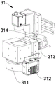
In order to improve the material taking accuracy of the rotary turnover mechanism 32, the rotary turnover loading and unloading device 3 further comprises a positioning detection mechanism 31 arranged on the workbench 10, the positioning detection mechanism 31 is located on one side, away from the loading and unloading mechanism 33, of the rotary turnover mechanism 32 in the Y-axis direction, the positioning detection mechanism 31 comprises a positioning camera 311, a positioning plate 313 and a positioning driving mechanism, the positioning driving mechanism can control the positioning plate 313 to move in the Y-axis direction, and the positioning camera 311 is arranged on the positioning plate 313. In order to scan the two-dimensional codes of different positions of the material, the positioning detection mechanism 31 further comprises a first dimension code scanner 312, the first dimension code scanner 312 is arranged on the positioning plate 313, the rotatable overturning loading and unloading device 3 further comprises a second dimension code scanner 35 arranged on the workbench 10, and the second dimension code scanner 35 is located below the first dimension code scanner 312 in the Z-axis direction.
In order to improve the stability and reliability of the transmission operation, the moving driving mechanism includes a first driving mechanism, a second driving mechanism, a first screw 327 and a first nut, the turning mechanism 32 further includes a second moving plate 326, the first driving mechanism can control the second moving plate 326 to move in the Y-axis direction, the first screw 327 extends in the Z-axis direction and is rotatably supported on the second moving plate 326, the first nut is movably sleeved on the first screw 327 in the Z-axis direction, and the first moving plate 321 is arranged on the first nut; the moving driving mechanism comprises a third driving mechanism, a fourth driving mechanism, a second screw 334 and a second nut, the loading and unloading mechanism 33 further comprises a second moving plate 335, the third driving mechanism can control the second moving plate 335 to move in the Y-axis direction, the second screw 334 extends in the Z-axis direction and is rotatably supported on the second moving plate 335, the second nut is movably sleeved on the second screw 334 in the Z-axis direction, and the first moving plate 331 is arranged on the second nut; the rotatable overturning loading and unloading device 3 further comprises a portal frame, two upright columns 361 of the portal frame are mounted on the workbench 10, a cross beam 36 of the portal frame extends in the Y-axis direction, a slide rail 37 extending in the Y-axis direction is arranged on the cross beam 36, a first slide block is arranged on the positioning plate 313, a second slide block is arranged on the second moving plate 326, a third slide block is arranged on the second moving plate 335, and the first slide block, the second slide block and the third slide block can be matched with the slide rail 37 in a movable manner in the Y-axis direction; a first induction plate 328 and a second induction plate 329 are respectively arranged on two sides of the second moving plate 326 in the Y-axis direction, a first inductor 314 is arranged on one side of the positioning plate 313 close to the second moving plate 326 in the Y-axis direction, a first through groove is formed in the first inductor 314, the first induction plate 328 is movably inserted into the first through groove of the first inductor 314 in the Y-axis direction, a second inductor 336 is arranged on one side of the second moving plate 335 close to the second moving plate 326 in the Y-axis direction, a second through groove is formed in the second inductor 336, and the second induction plate 329 is movably inserted into the second through groove in the Y-axis direction.
Referring to fig. 19, the optical testing apparatus 4 includes an AOI camera 41 and a testing control mechanism 42, the AOI camera 41 is located above the material conveying mechanism 8 in the Z-axis direction, the testing control mechanism 42 can control the AOI camera 41 to move in the Z-axis direction and the Y-axis direction respectively, the AOI camera 41 automatically scans and acquires images of the attachment surface of the material on the material conveying mechanism 8, compares the images with qualified parameters in the database, and after image processing, detects defects on the attachment surface of the material, and displays/marks the defects through a display or an automatic mark. The test control mechanism 42 controls the AOI camera 41 to move in the Z-axis direction and the Y-axis direction by using two test motors 421, two test screws 422, and two test nuts.
Referring to fig. 20 and 21, the number of the material conveying mechanisms 8 is three, three material conveying mechanisms 8 are arranged side by side in the Y-axis direction, correspondingly, the number of the glue dispensing mechanisms 51 of the glue dispensing device 5 is four, one glue dispensing mechanism 51 performs glue dispensing work corresponding to one material conveying mechanism 8, and one glue dispensing mechanism 51 is preset to be used. Each glue dispensing mechanism 51 comprises a mounting plate 512, a CCD camera 513, a height measurement sensor 514, a glue dispenser 511 and a glue dispensing control mechanism, wherein the glue dispenser 511, the CCD camera 513 and the height measurement sensor 514 are respectively arranged on the mounting plate 512 and are positioned above the material conveying mechanism 8 in the Z-axis direction, and the glue dispensing control mechanism can control the mounting plate 512 to drive the glue dispenser 511, the CCD camera 513 and the height measurement sensor 514 to respectively move in the Z-axis direction and the Y-axis direction. The CCD camera 513 of the dispensing device 5 is used for taking pictures of the materials on the material conveying mechanism 8 and calculating the accurate positions of the materials, the height measuring sensor 514 is used for detecting the height of the materials in the Z-axis direction, and then the dispensing device 511 performs dispensing on the attaching surfaces of the materials, so that the stability and the accuracy of dispensing work are improved.
Referring to fig. 22 to 27, the high-precision bonding apparatus 6 includes a first positioning mechanism 61, a bonding mechanism 62, a quality detection mechanism 63, and a material taking mechanism 64, the quality detection mechanism 63 is located between the bonding mechanism 62 and the material taking mechanism 64 in the Y-axis direction, the first positioning mechanism 61 is located on one side of the bonding mechanism 62 away from the material taking mechanism 64 in the Y-axis direction and is located above the material conveying mechanism 8 in the Z-axis direction, the first positioning mechanism 61 includes a first transfer control mechanism, a first transfer seat 611, and a first camera 612, the first transfer control mechanism can control the first transfer seat 611 to move in the Y-axis direction and the Z-axis direction, respectively, and the first camera 612 is disposed on the first transfer seat 611. The material taking mechanism 64 includes a transfer control mechanism, a first transfer seat 641 and a first vacuum material taking nozzle 642, the transfer control mechanism can control the first transfer seat 641 to move in the X-axis direction, the Y-axis direction and the Z-axis direction respectively, the first vacuum material taking nozzle 642 is disposed on the first transfer seat 641, the quality detection mechanism 63 includes a rotation control mechanism 633, a rotation disk 631 and an AOI optical detector 634, the rotation control mechanism 633 can control the rotation disk 631 to rotate around the Z-axis, the rotation disk 631 is provided with a plurality of through slots 632, the plurality of through slots 632 are uniformly distributed around the rotation axis of the rotation disk 631 and are disposed through the rotation disk 631 in the Z-axis direction, and the AOI optical detector 634 is located below the rotation disk 631 in the Z-axis direction and is disposed opposite to the through slots 632. Attaching mechanism 62 is including carrying control mechanism, the first seat 621 of carrying, material mouth 622 and two UV exposure lamps 623 of carrying is got in the second vacuum, it carries the controllable first seat 621 of carrying of control mechanism and moves respectively on the X axle direction, Y axle direction and Z axle direction, material mouth 622 and two UV exposure lamps 623 of getting in the second vacuum set up respectively on the first seat 621 of carrying, and two UV exposure lamps 623 are located the periphery that the material mouth 622 was got in the second vacuum respectively and get the slope setting of material mouth 622 towards the second vacuum. A transfer control mechanism of the material taking mechanism 64 controls a first transfer seat 641 to drive a first vacuum material taking nozzle 642 to move in the X-axis direction, the Y-axis direction and the Z-axis direction, so that the first vacuum material taking nozzle 642 moves to the upper part of the wafer feeding device 9 and adsorbs auxiliary materials of the wafer feeding device 9, then the transfer control mechanism controls the first transfer seat 641 to drive the first vacuum material taking nozzle 642 and the auxiliary materials to move in the X-axis direction, the Y-axis direction and the Z-axis direction to a through groove 632 of a rotating disc 631 of a quality detection mechanism 63, the first vacuum material taking nozzle 642 releases the auxiliary materials to be placed on the rotating disc and correspond to the through groove 632, then the rotation control mechanism of the quality detection mechanism 63 controls the rotating disc 631 to rotate around the Z-axis so that the auxiliary materials are positioned right above an AOI optical detector 634, the AOI optical detector 634 passes through the through groove 632 to automatically scan an attaching surface of the auxiliary materials, acquire images, compare with qualified parameters in a database, the images, inspect defects on the attaching surface of the material, display material by a mark 631 of the attaching device 631, display, the mark 631, the mark on the X-axis of the second vacuum material taking seat 631, the X-axis direction, the vacuum material taking nozzle 62 controls the vacuum material taking nozzle 62 and the second vacuum material taking mechanism 62 to control the second vacuum mechanism and the vacuum material taking nozzle 62, controls the vacuum mechanism to rotate around the X-axis direction, and the second vacuum material taking nozzle 621, controls the second vacuum nozzle 621, controls the vacuum material taking nozzle 621, make the auxiliary material remove to the top of material transport mechanism 8, the first control mechanism that transfers of first positioning mechanism 61 controls first transfer seat 611 and drives first camera 612 and move respectively in Y axle direction and Z axle direction and shoot the location to the attached material of treating on the material transport mechanism 8, then the second vacuum is got material mouth 622 and is loosened the auxiliary material and attached on the material of shooting the location on material transport mechanism 8, glue on two UV exposure lamps 623 are to the attached face of material simultaneously makes glue solidification tentatively for the heat, thereby avoid the subassembly after the subsides to lead to appearing the dislocation between material and the auxiliary material when material transport mechanism 8 carries to next station, guarantee attached stability between material and the auxiliary material. High accuracy laminating device 6 can ensure the quality precision of material and auxiliary material through setting up first positioning mechanism 61 and quality detection mechanism 63 to improve the yields of attached production, degree of automation is high moreover, and job stabilization is reliable, and simple structure is compact, and then reduction in production cost.
In order to improve the working accuracy of the material taking mechanism 64, the high-accuracy laminating device 6 further includes a second positioning mechanism 65 disposed on the table 10, the second positioning mechanism 65 is located on the side of the quality detection mechanism 63 away from the first positioning mechanism 61 in the Y-axis direction, the second positioning mechanism 65 includes a second transfer control mechanism, a second transfer seat 651 and a second camera 652, the second transfer control mechanism can control the second transfer seat 651 to move in the Y-axis direction, and the second camera 652 is disposed on the second transfer seat 651. In order to improve the material taking accuracy of the attaching mechanism 62, the high-accuracy attaching device 6 further includes a third camera 66 disposed on the workbench 10, the third camera 66 is located above the rotating disc 631 in the Z-axis direction, the third camera 66 is located on one side of the rotating disc 631 away from the material taking mechanism 64 in the Y-axis direction and is disposed opposite to the through groove 632, and the high-accuracy attaching device 6 further includes a fourth camera 68 disposed on the workbench 10, and the fourth camera 68 is located below the rotating disc 631 in the Z-axis direction and is disposed opposite to the third camera 66. Because some materials are soft at normal temperature and need to be heated and hardened for convenient attachment, the end face of the rotating disk 631 close to the AOI optical detector 634 in the Z-axis direction is provided with a plurality of heating rings, and one heating ring is arranged around the periphery of one through groove 632. In order to adjust the inclination angle of the UV exposure lamp 623, the attaching mechanism 62 further includes a first mounting plate 624 and two second mounting plates 625, a first end of the first mounting plate 624 is mounted on the first carrying seat 621, a second end of the first mounting plate 624 is provided with two first circular holes 6241 and two arc-shaped holes 6242, one arc-shaped hole 6242 extends with one first circular hole 6241 as an axis, one UV exposure lamp 623 is mounted on one second mounting plate 625, each second mounting plate 625 is provided with two second circular holes 6251, a first fastener passes through one first circular hole 6241 and one second circular hole 6251 to lock the second mounting plate 625 with the first mounting plate 624, and a second fastener passes through one arc-shaped hole 6242 and one second circular hole 6251 to lock the second mounting plate 625 with the first mounting plate 624.
In order to improve the stability and reliability of the transmission operation, the transferring control mechanism includes a first control mechanism, a second control mechanism and a third control mechanism, the material taking mechanism 64 further includes a second transferring seat 644 and a third transferring seat 643, the first control mechanism can control the second transferring seat 644 to move in the Y-axis direction, the second control mechanism is disposed on the second transferring seat 644 and can control the third transferring seat 643 to move in the X-axis direction, the third control mechanism is disposed on the third transferring seat 643 and can control the first transferring seat 641 to move in the Z-axis direction; the carrying control mechanism includes a fourth control mechanism, a fifth control mechanism and a sixth control mechanism, the attaching mechanism 62 further includes a second carrying seat 627 and a third carrying seat 626, the fourth control mechanism can control the second carrying seat 627 to move in the Y-axis direction, the fifth control mechanism is disposed on the second carrying seat 627 and can control the third carrying seat 626 to move in the X-axis direction, and the sixth control mechanism is disposed on the third carrying seat 626 and can control the first carrying seat 621 to move in the Z-axis direction; the first transfer control mechanism includes a seventh control mechanism and an eighth control mechanism, the first positioning mechanism 61 further includes a third transfer seat 613, the seventh control mechanism can control the third transfer seat 613 to move in the Y-axis direction, and the eighth control mechanism is disposed on the third transfer seat 613 and can control the first transfer seat 611 to move in the Z-axis direction; the high-precision bonding apparatus 6 further includes a suspension 67 provided on the table 10 and extending in the Y-axis direction, the suspension 67 is provided with a first guide rail 673 extending in the Y-axis direction, the second transfer base 644 is provided with a first guide block which is engaged with the first guide rail 673 so as to be movable in the Y-axis direction, the suspension 67 is provided with a second guide rail 672 extending in the Y-axis direction, the second transfer base 627 is provided with a second guide block which is engaged with the second guide rail 672 so as to be movable in the Y-axis direction, the suspension 67 is provided with a third guide rail 671 extending in the Y-axis direction, the third transfer base 613 is provided with a third guide block which is engaged with the third guide rail 671 so as to be movable in the Y-axis direction, the suspension 67 is provided with a fourth guide rail 674 extending in the Y-axis direction, the second transfer base 651 is provided with a fourth guide block which is engaged with the fourth guide rail 674 so as to be movable in the Y-axis direction; the first transfer seat 641 is provided with a first grating scale 645, the first transfer seat 621 is provided with a second grating scale 628, and the first transfer seat 611 is provided with a third grating scale 614, which is used for reading the moving data in the Z-axis direction.
Referring to fig. 28, the ultraviolet lamp 7 is located above the material conveying mechanism 8 in the Z-axis direction and can give heat to the glue between the components formed by the attachment of the materials and the auxiliary materials on the material conveying mechanism 8 to further cure the glue, so as to further ensure the attachment stability between the materials and the auxiliary materials.
Referring to fig. 29 to 33, the wafer loading apparatus 9 is disposed near the material taking mechanism 64 of the high-precision bonding apparatus 6, the wafer loading apparatus 9 includes a film expanding mechanism and a jacking mechanism, the film expanding mechanism includes a sliding plate 93, a sliding control mechanism, a receiving plate 94, a receiving control mechanism, a baffle plate 95, a film expanding ring 915 and a rotation control mechanism, the sliding control mechanism can control the sliding plate 93 to move in the X-axis direction, the receiving plate 94 can be movably supported above the sliding plate 93 in the Z-axis direction, and the receiving control mechanism can control the receiving plate 94 to move in the Z-axis direction. The bearing plate 94 is provided with a film expanding hole 941 in a penetrating manner in the Z-axis direction, the baffle 95 is arranged on the bearing plate 94 adjacent to the periphery of the film expanding hole 941, a limit gap is formed between the baffle 95 and the bearing plate 94 in the Z-axis direction, the film expanding ring 915 can be rotatably supported on the sliding plate 93 around the Z-axis direction, the rotation control mechanism can control the film expanding ring 915 to rotate around the Z-axis direction, and the edge end of the film expanding ring 915 can be inserted into the film expanding hole 941. The jacking mechanism comprises a vacuum sleeve 914, an operation control mechanism, a jacking column 916 and a jacking control mechanism, wherein the operation control mechanism can control the vacuum sleeve 914 to move in the Y-axis direction, the top end of the vacuum sleeve 914 is inserted into an annular hole of a film expanding ring 915, a plurality of vacuum sucking holes 9141 are formed in the top end face of the vacuum sleeve 914, the jacking column 916 extends in the Z-axis direction and is movably located in the vacuum sleeve 914 in the Z-axis direction, a plurality of ejector pins 917 protrude from the top end of the jacking column 916, the ejector pins 917 extend in the Z-axis direction and movably penetrate through the top end face of the vacuum sleeve 914, and the jacking control mechanism is arranged on the vacuum sleeve 914 and can control the jacking column 916 to move in the Z-axis direction. The stainless steel ring for packaging the blue film of the wafer is positioned in a limiting gap formed between the baffle 95 and the receiving plate 94 in the Z-axis direction, the receiving control mechanism controls the receiving plate 94 to drive the wafer auxiliary material to move downwards in the Z-axis direction towards the film expanding ring 915, so that the film expanding edge end of the film expanding ring 915 passively pushes the blue film of the wafer auxiliary material, the blue film can be expanded and tightened, after the blue film is expanded, a gap is formed between every two adjacent chips on the blue film, the interaction force between the two adjacent chips disappears, meanwhile, the rotation control mechanism controls the film expanding ring 915 to rotate around the Z-axis direction to adjust the angle of the wafer auxiliary material, then the sliding control mechanism can control the sliding plate 93 to drive the receiving plate 94, the baffle 95 and the film expanding ring 915 to move in the X-axis direction for feeding operation, and simultaneously the operation control mechanism of the jacking mechanism controls the vacuum sleeve 914 to drive the jacking column 916 to move in the Y-axis direction, when the vacuum sleeve 914 is located below the wafer chip to be loaded, the vacuum sleeve 914 adsorbs the local blue film corresponding to the wafer chip downwards through the vacuum suction hole 9141, and then the jacking control mechanism controls the jacking column 916 to move towards the wafer chip in the Z-axis direction, so that the thimble 917 located on the top end of the jacking column 916 penetrates out of the top end surface of the vacuum sleeve 914 to jack the wafer chip upwards, thereby the adhesive force between the wafer chip and the blue film can be greatly weakened, then the first vacuum material taking nozzle of the material taking mechanism 64 is adsorbed on the wafer chip, the wafer chip can be rapidly stripped from the blue film only by small adsorption grabbing force, the stability of the peripheral chip is influenced by the local deformation of the blue film can be effectively avoided, the work is stable and reliable, the automation degree is high, and the work efficiency is high.
In order to improve the stability and reliability of transmission work, the operation control mechanism comprises an operation motor 9111, an operation screw rod 9112 and an operation nut 9113, the operation screw rod 9112 extends in the Y-axis direction, the operation motor 9111 can control the operation screw rod 9112 to rotate around the Y-axis direction, the operation nut 9113 can be movably sleeved on the operation screw rod 9112 in the Y-axis direction, the vacuum sleeve 914 is arranged on the operation nut 9113, and the jacking control mechanism is a voice coil motor 9110; the sliding control mechanism comprises a sliding motor 99, a sliding lead screw 910 and a sliding nut, the sliding lead screw 910 extends in the X-axis direction, the sliding motor 99 can control the sliding lead screw 910 to rotate around the X-axis direction, the sliding nut can movably sleeve the sliding lead screw 910 in the X-axis direction, and the sliding plate 93 is arranged on the sliding nut; the carrying control mechanism comprises a carrying motor 9114, a carrying lead screw 9118, a carrying nut, a first driving wheel 9115, a first driven wheel 9116 and a first synchronous belt 9117, wherein the carrying motor 9114 is arranged on a sliding plate 93, a driving shaft of the carrying motor 9114 extends in the Z-axis direction, the first driving wheel 9115 is sleeved on the driving shaft of the carrying motor 9114, the carrying nut is arranged on the sliding plate 93, the carrying lead screw 9118 extends in the Z-axis direction to penetrate through the carrying nut and can rotate around the Z-axis direction, the carrying plate 94 and the first driven wheel 9116 are arranged at two ends of the carrying lead screw 9118 in the Z-axis direction, the first synchronous belt 9117 is sleeved between the first driven wheel 9116 and the first driving wheel 9115, specifically, the number of the carrying lead screw 9118 and the carrying nut is four, the four carrying lead screws 9118 are distributed at four corner positions of the carrying plate 94, one carrying nut is matched with one carrying lead screw 9118, the first driven wheel 9116 is sleeved on one of the first driven wheel 9118, and a third driven wheel 9119 is sleeved on each carrying lead screw 9118, and a fourth synchronous belt 9120 is sleeved between the fourth driven wheel 9119; rotation control mechanism includes rotation motor 9121, third action wheel 9122 and third hold-in range 9123, and rotation motor 9121 sets up on sliding plate 93, and the drive shaft that rotates motor 9121 extends in the Z axle direction, and third action wheel 9122 cup joints in the drive shaft that rotates motor 9121, and third hold-in range 9123 cover is established between third action wheel 9122 and expand membrane ring 915, and the outside of third hold-in range 9123 is provided with rotation support tension pulley 9124 on sliding plate 93.
In order to improve the working reliability of the jacking column 916, the bottom end of the jacking column 916 extends out of the vacuum sleeve 914 in the Z-axis direction and is provided with a stopper 919, the bottom end of the jacking column 916 is sleeved with a pressure spring 918, and two ends of the pressure spring 918 in the Z-axis direction are respectively pressed between the stopper 919 and the vacuum sleeve 914. When the jacking control mechanism controls the jacking column 916 to move towards the wafer chip in the Z-axis direction, so that the ejector pin 917 located at the top end of the jacking column 916 penetrates through the top end surface of the vacuum sleeve 914 to jack the wafer chip upwards, the blue film can provide a downward reaction force for the ejector pin 917, and in order to avoid damage to the blue film caused by upward movement due to collision of the ejector pin 917, two ends of the pressure spring 918 in the Z-axis direction respectively abut against the space between the stopper 919 and the vacuum sleeve 914, so that the ejector pin 917 can be provided with a space for driving the jacking column 916 to have downward buffer movement, and the working reliability of the jacking column 916 and the ejector pin 917 is ensured.
In order to improve the automatic production efficiency, the wafer loading device 9 further includes a basket lifting mechanism 91 located outside the film expanding mechanism in the X-axis direction, the basket lifting mechanism 91 includes a material carrying plate 911 and a material carrying control mechanism 912, the material carrying control mechanism 912 can control the material carrying plate 911 to move in the Z-axis direction, the film expanding mechanism further includes a linkage arm 96, a linkage control mechanism, a first air claw 97, a second air claw 98 and an air claw control mechanism, the linkage arm 96 can be movably supported on the sliding plate 93 in the X-axis direction, the linkage control mechanism can control the linkage arm 96 to move in the X-axis direction, the air claw control mechanism is disposed on the linkage arm 96 and can control the first air claw 97 and the second air claw 98 to move towards or away from each other, and the first air claw 97 and the second air claw 98 can be synchronously disposed through the baffle 95 to move in the X-axis direction. An auxiliary material turnover box is placed on the material carrying plate 911, the material carrying control mechanism 912 controls the material carrying plate 911 to move in the Z-axis direction to the same height as the first air claw 97 and the second air claw 98, then the linkage control mechanism can control the linkage arm 96 to drive the first air claw 97 and the second air claw 98 to move towards the auxiliary material turnover box in the X-axis direction, then the air claw control mechanism can control the first air claw 97 and the second air claw 98 to move towards each other so as to clamp an auxiliary material plate in the auxiliary material turnover box, then the linkage control mechanism can control the linkage arm 96 to drive the first air claw 97, the second air claw 98 and the auxiliary material plate to move towards a limiting gap formed between the baffle 95 and the bearing plate 94 in the Z-axis direction in the X-axis direction, so that the auxiliary material plate is limited in the limiting gap, and then the automatic auxiliary material feeding operation is completed. Specifically, the linkage control mechanism includes a linkage motor 913, a second driving wheel, a second driven wheel and a second synchronous belt, the linkage motor 913 is disposed on the sliding plate 93, a driving shaft of the linkage motor 913 extends in the Y-axis direction, the second driving wheel is sleeved on the driving shaft of the linkage motor 913, the second driving wheel and the second driven wheel are disposed side by side in the X-axis direction, the second synchronous belt is sleeved between the second driven wheel and the second driving wheel, and the linkage arm 96 is disposed on the second synchronous belt.
In order to reduce the risk of contamination of the auxiliary material on the wafer loading device 9, the wafer loading device 9 further includes a protective cover 92, the protective cover 92 covers the sliding plate 93 and extends to the local shielding film-expanding hole 941 above the baffle 95, and the side surface of the protective cover 92 close to the basket-lifting mechanism 91 is provided with a avoiding groove 921 for the auxiliary material tray to pass through. In order to stably limit the stainless steel ring for packaging the blue film of the wafer, the number of the baffles 95 is two, the two baffles 95 are symmetrically arranged about the axis of the film expanding hole 941, each baffle 95 is arranged in a circular arc shape around the axis of the film expanding hole 941, and two avoiding grooves for the first air claw 97 and the second air claw 98 to pass through are formed at two circumferential ends of the film expanding hole 941 of the two baffles 95.
Referring to fig. 34 and 35, in an embodiment where the wafer loading apparatus 9 is used for loading the tray 9126, the baffle 9125 is provided with a spring plunger near the positioning end of the bearing plate 94, and the spring of the spring plunger can force the positioning ball 9127 of the spring plunger to move towards the bearing plate 94 and protrude out of the positioning end of the baffle 9125. After the tray 9126 is loaded from the basket lifting mechanism 91 by the first air claw 97 and the second air claw 98, the periphery of the tray 9126 is limited in a limiting gap formed between the baffle 9125 and the receiving plate 94 in the Z-axis direction, because the baffle 9125 is provided with a spring plunger close to the positioning end of the receiving plate 94, a positioning bead 9127 of the spring plunger is pressed against the periphery of the tray 9126 under the forcing action of a spring, so that the periphery of the tray 9126 is stably limited in the limiting gap, and then in the auxiliary material loading process, the rotation control mechanism does not need to control the film expanding ring 915 to rotate around the Z-axis direction, the operation control mechanism does not need to control the vacuum sleeve 914 to move in the Y-axis direction, and the jacking control mechanism does not need to control the jacking column 916 to move in the Z-axis direction, so that the wafer loading device 9 can be compatible with the rigid tray 9126 and the wafer blue film loading.
The above embodiments are merely preferred examples of the present invention, and not intended to limit the scope of the invention, so that equivalent changes or modifications made based on the structure, characteristics and principles of the invention as claimed should be included in the claims of the present invention.
Claims (10)
1. The multifunctional camera assembly automatic attaching equipment is characterized by comprising a rotatable overturning feeding and discharging device, an optical testing device, a glue dispensing device, a high-precision attaching device, an ultraviolet lamp and a material conveying mechanism, wherein the rotatable overturning feeding and discharging device, the optical testing device, the glue dispensing device, the high-precision attaching device and the ultraviolet lamp are sequentially arranged side by side in the X-axis direction, the material conveying mechanism is used for conveying materials in the X-axis direction, and the ultraviolet lamp is positioned above the material conveying mechanism in the Z-axis direction;
the rotatable overturning loading and unloading device comprises an overturning mechanism, a transfer mechanism and a loading and unloading mechanism, wherein the overturning mechanism, the transfer mechanism and the loading and unloading mechanism are sequentially arranged side by side in a Y-axis direction, the loading and unloading mechanism is positioned above the material conveying mechanism in the Z-axis direction, the overturning mechanism comprises a moving driving mechanism, a first moving plate, a rotating control mechanism, an overturning control mechanism, a suction nozzle seat and a first vacuum suction nozzle, the moving driving mechanism can control the first moving plate to move in the Y-axis direction and the Z-axis direction respectively, the overturning control mechanism is arranged on the first moving plate and can control the suction nozzle seat to rotate around the X-axis direction, the rotating control mechanism and the first vacuum suction nozzle are arranged on the suction nozzle seat respectively, the rotating control mechanism can control the first rotary table vacuum suction nozzle to rotate around the axis of the rotating control mechanism, the middle rotating mechanism comprises a middle rotating table and a lifting driving mechanism, the lifting driving mechanism can control the middle rotating table to move in the Z-axis direction, the loading and unloading mechanism comprises a lifting driving mechanism and a first lifting driving mechanism, the first lifting driving mechanism can control the first moving plate to move on the Y-axis direction or the second vacuum suction nozzle to move in the Z-axis direction, and the vacuum suction nozzle is arranged on the first lifting plate;
the optical testing device comprises an AOI camera and a testing control mechanism, the AOI camera is positioned above the material conveying mechanism in the Z-axis direction, the testing control mechanism can control the AOI camera to move in the Z-axis direction and the Y-axis direction respectively, the dispensing device comprises a dispenser and a dispensing control mechanism, the dispenser is positioned above the material conveying mechanism in the Z-axis direction, the dispensing control mechanism can control the dispenser to move in the Z-axis direction and the Y-axis direction respectively, the high-precision laminating device comprises an attaching mechanism, a quality detection mechanism and a material taking mechanism, the quality detection mechanism is positioned between the attaching mechanism and the material taking mechanism in the Y-axis direction, the quality detection mechanism comprises a rotating control mechanism, a rotating disc and an AOI optical detector, the rotating control mechanism can control the rotating disc to rotate around the Z-axis, the rotating disc is provided with a plurality of through grooves, the plurality of through grooves are uniformly distributed around a rotating shaft of the rotating disc and penetrate through the rotating disc in the Z-axis direction, the plurality of through grooves are arranged below the rotating disc in the Z-axis direction and are opposite to the rotating disc, the material taking mechanism comprises a first material carrying and a first vacuum transfer control mechanism, and a first material carrying and a first vacuum transfer mechanism, a first material carrying and a first vacuum transfer mechanism, which are arranged in the first vacuum transfer mechanism;
the attaching mechanism comprises a carrying control mechanism, a first carrying seat, a second vacuum material taking nozzle and two UV exposure lamps, the carrying control mechanism can control the first carrying seat to move in the X-axis direction, the Y-axis direction and the Z-axis direction respectively, the second vacuum material taking nozzle and the two UV exposure lamps are arranged on the first carrying seat respectively, and the two UV exposure lamps are located on the periphery of the second vacuum material taking nozzle respectively and are arranged in an inclined mode towards the second vacuum material taking nozzle.
2. The multi-function camera assembly automated attachment apparatus of claim 1, wherein:
the rotatable overturning feeding and discharging device further comprises a positioning detection mechanism, and the positioning detection mechanism is positioned on one side of the rotatable overturning mechanism, which is far away from the feeding and discharging mechanism, in the Y-axis direction;
the positioning detection mechanism comprises a positioning camera, a positioning plate and a positioning driving mechanism, the positioning driving mechanism can control the positioning plate to move in the Y-axis direction, and the positioning camera is arranged on the positioning plate.
3. The automated multi-function camera assembly attachment apparatus of claim 2, wherein:
the positioning detection mechanism further comprises a first dimension code scanner, and the first dimension code scanner is arranged on the positioning plate.
4. The multi-function camera assembly automated attachment apparatus of claim 3, wherein:
the rotatable overturning feeding and discharging device further comprises a second dimension code scanner, and the second dimension code scanner is located below the first dimension code scanner in the Z-axis direction.
5. The automated multi-function camera assembly attachment apparatus of claim 1, wherein:
the high-precision laminating device further comprises a first positioning mechanism, the first positioning mechanism is positioned on one side, away from the material taking mechanism, of the attaching mechanism in the Y-axis direction and is positioned above the material conveying mechanism in the Z-axis direction, the first positioning mechanism comprises a first transfer control mechanism, a first transfer seat and a first camera, the first transfer control mechanism can control the first transfer seat to move in the Y-axis direction and the Z-axis direction respectively, and the first camera is arranged on the first transfer seat;
and/or the high-precision laminating device further comprises a second positioning mechanism, the second positioning mechanism is positioned on one side, away from the first positioning mechanism, of the quality detection mechanism in the Y-axis direction, the second positioning mechanism comprises a second transfer control mechanism, a second transfer seat and a second camera, the second transfer control mechanism can control the second transfer seat to move in the Y-axis direction, and the second camera is arranged on the second transfer seat;
and/or the high-precision laminating device further comprises a third camera, the third camera is located above the rotating disc in the Z-axis direction, and the third camera is located on one side, away from the material taking mechanism, of the rotating disc in the Y-axis direction and is arranged opposite to the through groove;
and/or, the high-precision laminating device further comprises a fourth camera, the fourth camera is located below the rotating disc in the Z-axis direction and located on one side, far away from the material taking mechanism, of the rotating disc in the Y-axis direction, and the fourth camera and the through groove are arranged oppositely.
6. The automated multi-function camera assembly attachment apparatus of claim 1, wherein:
the end face, close to the AOI optical detector, of the rotating disc in the Z-axis direction is provided with a plurality of heating rings, and one heating ring is arranged on the periphery of one through groove in a surrounding mode.
7. The automated multi-function camera assembly attachment apparatus of claim 1, wherein:
the multifunctional camera assembly automatic attaching equipment further comprises a wafer feeding device arranged close to the taking mechanism, the wafer feeding device comprises a film expanding mechanism and a jacking mechanism, the film expanding mechanism comprises a sliding plate, a sliding control mechanism, a bearing plate, a bearing control mechanism, a baffle plate, a film expanding ring and a rotation control mechanism, the sliding control mechanism can control the sliding plate to move in the X-axis direction, the bearing plate can be movably supported above the sliding plate in the Z-axis direction, and the bearing control mechanism can control the bearing plate to move in the Z-axis direction;
the bearing plate is provided with a film expanding hole in a penetrating manner in the Z-axis direction, the baffle plate is arranged on the bearing plate in a manner of being adjacent to the periphery of the film expanding hole, a limit gap is formed between the baffle plate and the bearing plate in the Z-axis direction, the film expanding ring can be rotationally supported on the sliding plate around the Z-axis direction, the rotation control mechanism can control the film expanding ring to rotate around the Z-axis direction, and the film expanding edge end of the film expanding ring can be inserted into the film expanding hole;
the jacking mechanism comprises a vacuum sleeve, an operation control mechanism, a jacking column and a jacking control mechanism, wherein the operation control mechanism is controllable, the vacuum sleeve moves in the Y-axis direction, the top end of the vacuum sleeve is inserted into an annular hole of the film expanding ring, a plurality of vacuum suction holes are formed in the top end face of the vacuum sleeve, the jacking column extends in the Z-axis direction and can movably be located in the Z-axis direction in the vacuum sleeve, a plurality of ejector pins are arranged on the top end of the jacking column in a protruding mode and movably penetrate out of the top end face of the vacuum sleeve, and the jacking control mechanism is arranged on the vacuum sleeve and can control the jacking column to move in the Z-axis direction.
8. The multi-functional camera assembly automated attachment apparatus of any one of claims 1 to 7, wherein:
the multifunctional camera assembly automatic attaching equipment further comprises a double-layer conveying line which is arranged close to the rotary turnover mechanism, the double-layer conveying line comprises a first upper-layer conveying mechanism, a first lower-layer conveying mechanism and a first motion control mechanism, the first upper-layer conveying mechanism is located above the first lower-layer conveying mechanism in the Z-axis direction, the first upper-layer conveying mechanism comprises a first support frame, a first conveying belt, a second conveying belt and a first conveying control mechanism, the first conveying belt and the second conveying belt extend in the X-axis direction and are movably supported on the first support frame in the X-axis direction, the first conveying belt and the second conveying belt are arranged side by side in the Y-axis direction, and the first conveying control mechanism can control the first conveying belt and the second conveying belt to synchronously move in the X-axis direction;
first motion control mechanism is steerable first support frame removes in the X axle direction, first lower floor conveying mechanism includes second support frame, third conveyer belt, fourth conveyer belt and second transmission control mechanism, the third conveyer belt with the fourth conveyer belt extends in the X axle direction and can support with moving in the X axle direction on the second support frame, just the third conveyer belt with the fourth conveyer belt sets up side by side in the Y axle direction, second transmission control mechanism is steerable the third conveyer belt with the fourth conveyer belt removes in the X axle direction in step.
9. The multi-function camera assembly automated attachment apparatus of claim 8, wherein:
the number of the rotatable turnover feeding and discharging devices is two, one rotatable turnover feeding and discharging device is positioned on one side, away from the ultraviolet lamp, of the optical testing device in the X-axis direction, and the other rotatable turnover feeding and discharging device is positioned on one side, away from the optical testing device, of the ultraviolet lamp in the X-axis direction;
the double-layer conveying line further comprises a second upper-layer conveying mechanism and a second motion control mechanism, the second upper-layer conveying mechanism and the first upper-layer conveying mechanism are located between the two rotatable turnover loading and unloading devices in the X-axis direction, and the second upper-layer conveying mechanism is located above the first lower-layer conveying mechanism in the Z-axis direction;
the second upper conveying mechanism comprises a fifth supporting frame, a ninth conveying belt, a tenth conveying belt and a fifth conveying control mechanism, the ninth conveying belt and the tenth conveying belt extend in the X-axis direction and are movably supported on the fifth supporting frame in the X-axis direction, the ninth conveying belt and the tenth conveying belt are arranged side by side in the Y-axis direction, the fifth conveying control mechanism can control the ninth conveying belt and the tenth conveying belt to synchronously move in the X-axis direction, and the second movement control mechanism can control the fifth supporting frame to move in the X-axis direction.
10. The multi-function camera assembly automated attachment apparatus of claim 8, wherein:
the double-layer conveying line further comprises a feeding lifting mechanism, the feeding lifting mechanism is located at the first end of the first lower-layer conveying mechanism in the X-axis direction, the feeding lifting mechanism comprises a third support frame, a fifth conveying belt, a sixth conveying belt, a third conveying control mechanism and a first lifting control mechanism, the first lifting control mechanism can control the third support frame to move in the Z-axis direction, the fifth conveying belt and the sixth conveying belt extend in the X-axis direction and are movably supported on the third support frame in the X-axis direction, the fifth conveying belt and the sixth conveying belt are arranged side by side in the Y-axis direction, and the third conveying control mechanism can control the fifth conveying belt and the sixth conveying belt to synchronously move in the X-axis direction;
and/or, double-deck transfer chain still includes unloading elevating system, unloading elevating system is located in the X axle direction first lower floor conveying mechanism's second end, unloading elevating system includes fourth support frame, seventh conveyer belt, eighth conveyer belt, fourth conveying control mechanism and second lifting control mechanism, second lifting control mechanism is steerable the fourth support frame removes in the Z axle direction, the seventh conveyer belt with the eighth conveyer belt extends in the X axle direction and can support with moving in the X axle direction on the fourth support frame, just the seventh conveyer belt with the eighth conveyer belt sets up side by side in the Y axle direction, fourth conveying control mechanism is steerable the seventh conveyer belt with the eighth conveyer belt removes in step in the X axle direction.
Priority Applications (1)
| Application Number | Priority Date | Filing Date | Title |
|---|---|---|---|
| CN202210206017.7A CN114435913B (en) | 2022-03-02 | 2022-03-02 | Automatic attaching equipment of multifunctional camera assembly |
Applications Claiming Priority (1)
| Application Number | Priority Date | Filing Date | Title |
|---|---|---|---|
| CN202210206017.7A CN114435913B (en) | 2022-03-02 | 2022-03-02 | Automatic attaching equipment of multifunctional camera assembly |
Publications (2)
| Publication Number | Publication Date |
|---|---|
| CN114435913A CN114435913A (en) | 2022-05-06 |
| CN114435913B true CN114435913B (en) | 2022-11-25 |
Family
ID=81359195
Family Applications (1)
| Application Number | Title | Priority Date | Filing Date |
|---|---|---|---|
| CN202210206017.7A Active CN114435913B (en) | 2022-03-02 | 2022-03-02 | Automatic attaching equipment of multifunctional camera assembly |
Country Status (1)
| Country | Link |
|---|---|
| CN (1) | CN114435913B (en) |
Families Citing this family (1)
| Publication number | Priority date | Publication date | Assignee | Title |
|---|---|---|---|---|
| CN114918157B (en) * | 2022-05-25 | 2023-12-01 | 佑光智能半导体科技(深圳)有限公司 | Blue film separator and separation method |
Citations (9)
| Publication number | Priority date | Publication date | Assignee | Title |
|---|---|---|---|---|
| JP2000016560A (en) * | 1998-06-30 | 2000-01-18 | Ishikawajima Harima Heavy Ind Co Ltd | Face material supply device for panel for prefabricated house |
| CN103790911A (en) * | 2014-03-03 | 2014-05-14 | 尹先和 | High-precision liquid crystal display screen attachment machine |
| CN108289163A (en) * | 2018-03-30 | 2018-07-17 | 深圳市鹰眼在线电子科技有限公司 | Multi-cam module assembling apparatus |
| CN208712096U (en) * | 2018-08-24 | 2019-04-09 | 东莞触点智能装备有限公司 | A kind of abutted equipment |
| CN209334129U (en) * | 2018-12-13 | 2019-09-03 | 深圳市诺峰光电设备有限公司 | A kind of automatic on-line curer |
| CN110683336A (en) * | 2019-11-04 | 2020-01-14 | 东莞市鼎力自动化科技有限公司 | Camera module laminating equipment |
| CN111498487A (en) * | 2020-03-18 | 2020-08-07 | 深圳市鑫三力自动化设备有限公司 | Camera laminating equipment under screen |
| CN214059057U (en) * | 2020-11-18 | 2021-08-27 | 苏州卓翔自动化设备有限公司 | Product overturning and carrying mechanism |
| CN114093799A (en) * | 2021-10-28 | 2022-02-25 | 深圳市鹰眼在线电子科技有限公司 | Chip laminating equipment |
Family Cites Families (1)
| Publication number | Priority date | Publication date | Assignee | Title |
|---|---|---|---|---|
| JP7430515B2 (en) * | 2019-11-06 | 2024-02-13 | 株式会社ディスコ | Wafer processing method |
-
2022
- 2022-03-02 CN CN202210206017.7A patent/CN114435913B/en active Active
Patent Citations (9)
| Publication number | Priority date | Publication date | Assignee | Title |
|---|---|---|---|---|
| JP2000016560A (en) * | 1998-06-30 | 2000-01-18 | Ishikawajima Harima Heavy Ind Co Ltd | Face material supply device for panel for prefabricated house |
| CN103790911A (en) * | 2014-03-03 | 2014-05-14 | 尹先和 | High-precision liquid crystal display screen attachment machine |
| CN108289163A (en) * | 2018-03-30 | 2018-07-17 | 深圳市鹰眼在线电子科技有限公司 | Multi-cam module assembling apparatus |
| CN208712096U (en) * | 2018-08-24 | 2019-04-09 | 东莞触点智能装备有限公司 | A kind of abutted equipment |
| CN209334129U (en) * | 2018-12-13 | 2019-09-03 | 深圳市诺峰光电设备有限公司 | A kind of automatic on-line curer |
| CN110683336A (en) * | 2019-11-04 | 2020-01-14 | 东莞市鼎力自动化科技有限公司 | Camera module laminating equipment |
| CN111498487A (en) * | 2020-03-18 | 2020-08-07 | 深圳市鑫三力自动化设备有限公司 | Camera laminating equipment under screen |
| CN214059057U (en) * | 2020-11-18 | 2021-08-27 | 苏州卓翔自动化设备有限公司 | Product overturning and carrying mechanism |
| CN114093799A (en) * | 2021-10-28 | 2022-02-25 | 深圳市鹰眼在线电子科技有限公司 | Chip laminating equipment |
Also Published As
| Publication number | Publication date |
|---|---|
| CN114435913A (en) | 2022-05-06 |
Similar Documents
| Publication | Publication Date | Title |
|---|---|---|
| CN217296334U (en) | Rotatable overturning loading and unloading device | |
| KR101261266B1 (en) | Laser processing device and laser processing method using the same | |
| CN113314445B (en) | COB automatic assembly equipment | |
| WO2021164667A1 (en) | Wafer, and calibration apparatus and calibration method for transfer mechanism of wafer | |
| CN114643208B (en) | Optical lens flaw automatic detection equipment | |
| CN211707423U (en) | Rotating disc type watch glass lens detector | |
| CN110841929A (en) | Rotating disc type watch glass lens detector | |
| CN114435913B (en) | Automatic attaching equipment of multifunctional camera assembly | |
| CN116598233B (en) | Chip detection sorting equipment | |
| CN114566450B (en) | Wafer feeding device | |
| CN115452058A (en) | Automatic detecting mechanism for micro-element | |
| CN115610998A (en) | Fingerprint module detecting system and transport mechanism thereof | |
| CN115254644A (en) | Four-side detection equipment and method for DFB chip | |
| CN114435889A (en) | Double-layer conveying line | |
| CN216284939U (en) | Image acquisition device and detection equipment with same | |
| CN113567360B (en) | Color difference and gloss detection device compatible with multiple products and operation method thereof | |
| JPS6146971B2 (en) | ||
| CN217641262U (en) | High-precision laminating device | |
| CN209911252U (en) | Appearance detection equipment | |
| CN114895539B (en) | Chip lithography apparatus | |
| CN115682936A (en) | Turntable detection platform | |
| CN211907401U (en) | Wafer carrying disc placing and unloading device | |
| JP2010126242A (en) | Taping device | |
| CN114354648A (en) | Coating detection equipment and coating detection method | |
| JP2005017386A (en) | Device for inspecting and correcting flat plate work |
Legal Events
| Date | Code | Title | Description |
|---|---|---|---|
| PB01 | Publication | ||
| PB01 | Publication | ||
| SE01 | Entry into force of request for substantive examination | ||
| SE01 | Entry into force of request for substantive examination | ||
| GR01 | Patent grant | ||
| GR01 | Patent grant |