CN114432963B - Granulation machine and running state monitoring method thereof - Google Patents
Granulation machine and running state monitoring method thereof Download PDFInfo
- Publication number
- CN114432963B CN114432963B CN202210025203.0A CN202210025203A CN114432963B CN 114432963 B CN114432963 B CN 114432963B CN 202210025203 A CN202210025203 A CN 202210025203A CN 114432963 B CN114432963 B CN 114432963B
- Authority
- CN
- China
- Prior art keywords
- compression roller
- air
- air passage
- pressure
- rod
- Prior art date
- Legal status (The legal status is an assumption and is not a legal conclusion. Google has not performed a legal analysis and makes no representation as to the accuracy of the status listed.)
- Active
Links
Images


Classifications
-
- B—PERFORMING OPERATIONS; TRANSPORTING
- B01—PHYSICAL OR CHEMICAL PROCESSES OR APPARATUS IN GENERAL
- B01J—CHEMICAL OR PHYSICAL PROCESSES, e.g. CATALYSIS OR COLLOID CHEMISTRY; THEIR RELEVANT APPARATUS
- B01J2/00—Processes or devices for granulating materials, e.g. fertilisers in general; Rendering particulate materials free flowing in general, e.g. making them hydrophobic
- B01J2/22—Processes or devices for granulating materials, e.g. fertilisers in general; Rendering particulate materials free flowing in general, e.g. making them hydrophobic by pressing in moulds or between rollers
-
- G—PHYSICS
- G01—MEASURING; TESTING
- G01P—MEASURING LINEAR OR ANGULAR SPEED, ACCELERATION, DECELERATION, OR SHOCK; INDICATING PRESENCE, ABSENCE, OR DIRECTION, OF MOVEMENT
- G01P3/00—Measuring linear or angular speed; Measuring differences of linear or angular speeds
- G01P3/26—Devices characterised by the use of fluids
Landscapes
- Chemical & Material Sciences (AREA)
- Physics & Mathematics (AREA)
- General Physics & Mathematics (AREA)
- Organic Chemistry (AREA)
- Chemical Kinetics & Catalysis (AREA)
- Measuring Fluid Pressure (AREA)
- Press Drives And Press Lines (AREA)
Abstract
The invention relates to a granulator and a state monitoring method thereof, in particular to a ring die, wherein the ring die is rotatably arranged in the granulator, and a plurality of discharge holes are formed in the ring die; the compression roller shaft is arranged in the ring die and is sleeved with an outer spacer sleeve; the compression roller is rotatably arranged on the compression roller shaft and is configured to drive the outer spacer bush to rotate, and the compression roller is used for matching with the annular die and pressing the material into the discharge port; and the compression roller speed measuring device is arranged between the compression roller shaft and the outer spacer sleeve and is configured to be used for measuring the rotating speed of the outer spacer sleeve driven by the compression roller. This patent can solve the problem that can't in time obtain compression roller running state through above-mentioned structure.
Description
Technical Field
The invention relates to the field of feed production equipment, in particular to a granulator.
Background
At present, when production column feed, generally can use the column granulation machine, the principle generally for the material drop into behind the granulation machine, the ring mould is rotatory and drive the material and carry to the ring mould internal surface, be equipped with the compression roller in the ring mould and keep a bit clearance with the compression roller, promote the material in clearance this moment and can drive the compression roller rotatory and by the radial hole that sets up on the extrusion ring mould, the ring mould outside is equipped with the scraper and lasts and will scrape through the material that the ring mould extruded and cut off.
Because the clearance between the compression roller and the ring die is small, the working condition of equipment is easily influenced by the characteristics of materials in the production process, the clearance value between the compression roller and the ring die needs to be adjusted according to the characteristics of the materials, but when the clearance is too small, the ring die is easy to collapse or the compression roller slips and does not rotate along with the ring die, so that the materials cannot be pressed out, and when the conditions occur, the clearance value needs to be adjusted in time.
How to timely detect the use condition of the compression roller and whether the gap value is suitable for the granulation of the materials at the moment becomes a solution needed by the field.
Disclosure of Invention
In order to solve the problems, the invention provides a mechanism which can timely feed back whether the compression roller normally operates by measuring the rotation speed of the compression roller, and the speed measuring structure is not influenced by materials and can monitor the rotation speed of the compression roller in real time, and the specific scheme is as follows:
a granulation machine, comprising: the ring die is rotatably arranged in the granulator and is provided with a plurality of discharge holes; the compression roller shaft is arranged in the ring die and is sleeved with an outer spacer sleeve; the compression roller is rotatably arranged on the compression roller shaft and is configured to drive the outer spacer bush to rotate, and the compression roller is used for matching with the annular die and pressing the material into the discharge port; and the compression roller speed measuring device is arranged between the compression roller shaft and the outer spacer sleeve and is configured to be used for measuring the rotating speed of the outer spacer sleeve driven by the compression roller.
Above-mentioned scheme can be through experimenting out normal compression roller rotational speed in advance, real-time supervision compression roller rotational speed reacts the running state of compression roller again, and above-mentioned solved with speed sensor direct mount on the compression roller because the influence of material leads to measuring the inaccurate problem of speed, general speed sensor all locates the outside that needs detection device, and to being monitored by detection device, for example use devices such as the probe that tests the speed, but above-mentioned mode easily receives the influence of material and environment, at granulation machine material and ambient humidity, under the influence of temperature, use above-mentioned probe to lead to the damage of probe easily and measuring effect inaccurate, and adopt this design can locate compression roller speed sensor inside the compression roller, need not receive the material to interfere, and the rotational speed of compression roller is reacted to the rotational speed through measuring outer spacer, measure more accurately, this speed sensor installation is simple simultaneously need not add too much device in granulation machine inside, lead to the cost increase, the installation degree of difficulty increases.
A first bearing and a second bearing are further arranged on the compression roller shaft, the outer spacer bush is arranged between the first bearing and the second bearing and clamped by the outer rings of the first bearing and the second bearing, and a radial boss is arranged on the inner side of the outer spacer bush; still be equipped with interior spacer sleeve between the first bearing with the second bearing, interior spacer sleeve configuration is pressed from both sides tightly by first bearing with the second bearing inner circle, the compression roller speed sensor locate interior spacer sleeve with on the compression roller axle, and include: the connecting end is rotatably arranged on the outer side of the inner spacer bush and is configured to press down the movable end when the radial boss rotates to a position above the compression rod along with the rotation of the outer spacer bush; the ejector pin is arranged below the movable end and movably connected with the inner spacer sleeve in a penetrating manner; the connecting rod is positioned at the lower end of the ejector pin and movably arranged in a cavity formed in the compression roller shaft, a first spring is arranged at the lower end of the connecting rod, and the connecting rod is configured to force the air volume in the air passage to be reduced when being pressed down; the air passage penetrates through the compression roller shaft, and the head end of the air passage is communicated with the cavity; the air source is communicated with the air passage and continuously supplies compressed air into the air passage; a pressure detection device in communication with the end of the airway for detecting a change in pressure within the airway caused by depression of the linkage.
Above-mentioned scheme sets up the compression roller speed sensor into carrying out the machinery through measuring the pressure variation in the air flue and testing the speed, and it is better for setting up the sensor accuracy of testing the speed.
Further the airway includes: the first air passage is arranged in the compression roller shaft, and the second air passage is arranged in the main shaft for fixing the compression roller shaft; the first air passage is communicated with the second air passage, the main shaft is provided with a first air hole and a second air hole which are both communicated with the second air passage, and the first air hole and the second air hole are communicated with the air source; the first air hole with be connected with the check valve through the trachea between the air supply, the check valve is used for lasting with the compressed air that the air supply provided is leading-in extremely in the second air flue, the second air hole with be connected with the differential pressure gauge between the external trachea of check valve, the differential pressure gauge is used for detecting the pressure differential change of second air hole.
The rotation speed of the compression roller can be calculated through the pressure change frequency by arranging the differential pressure meter.
Further the airway includes: the first air passage is arranged in the compression roller shaft, and the second air passage is arranged in the main shaft for fixing the compression roller shaft; the first air passage is communicated with the second air passage, the main shaft is provided with a first air hole, a second air hole and a guide hole, the first air hole is communicated with the second air passage, one end of the guide hole is communicated with the second air passage and the first air hole, and a detection rod is inserted in the guide hole; the utility model discloses a pneumatic detection device, including first air duct, second air duct, detection pole, closing part, check valve, air supply, proximity switch, closing part, the closing part and with the pole portion that closing part one end is connected, the closing part adaptation in the guiding hole will the guiding hole is sealed, pole portion is located one side of guiding hole with second gas pocket intercommunication, be connected with the check valve through the trachea between the air supply, the check valve be used for lasting will compressed air that the air supply provided is leading-in extremely in the second air flue, along proximity switch is still installed in the outside that pole portion length direction extends, proximity switch is used for detecting pole portion approximate position.
Further the knock pin includes: the pressure head is movably connected in the inner spacer sleeve and is used for contacting the movable end when rotating to the position above the pressure rod with the outer spacer sleeve; one end of the pressing rod is connected to the lower end of the pressing head, and the other end of the pressing rod is abutted to the upper end of the connecting rod; and a second spring is also arranged in the inner spacer sleeve, and the second spring is sleeved on the abutting rod and is abutted against the lower end of the pressure head.
Furthermore, the movable end is provided with a rotating wheel through a pin shaft, and the outer circular surface of the rotating wheel is in contact with the pressure head.
Furthermore, a pressing plate is installed at the lower end of the connecting rod and arranged above the first spring, a first sealing ring is arranged between the pressing plate and the connecting rod, and the pressing plate is adapted to the cavity and seals the cavity.
Further, the outer side of the one-way valve is connected with a pressure regulating valve through an air pipe, and the pressure regulating valve is used for regulating the input pressure of the air source introduced into the second air passage.
In order to solve the above problems, the present invention further provides a method for monitoring the operation state of a granulation machine, which is as follows.
Step 1: setting the normal running rotating speed of the compression roller;
and 2, step: the method for measuring the rotating speed of the compression roller during the operation of the granulator in real time comprises the step of measuring the rotating speed of the compression roller by using a compression roller speed measuring device arranged between a compression roller shaft and an outer spacer bush, and specifically comprises the step of measuring the rotating speed of the compression roller by using the compression roller speed measuring device
The air source introduces compressed air into an air passage penetrating through the compression roller shaft, the air passage comprises a first air passage and a second air passage communicated with the first air passage, the first air passage is arranged in the compression roller shaft, the second air passage is arranged in a main shaft for fixing the compression roller shaft, and the air source inputs the compressed air into the first air passage and the second air passage respectively;
feeding materials into the granulator;
after the material enters the granulator, rotating the annular die and lifting the material to a gap between the compression roller and the annular die by matching with the compression roller;
the compression roller rotates along with the lifting of the material and drives the outer spacer bush on the inner side of the compression roller to rotate, and when the outer spacer bush rotates to the upper end of the compression rod, the radial boss on the inner side of the outer spacer bush presses down the movable end of the compression rod;
the movable end of the pressure lever presses down a top pin arranged in the inner spacer sleeve, the top pin presses down a connecting rod under stress, and the connecting rod drives the pressure plate to press down and discharge air in the cavity, so that the air volume in the first air passage and the second air passage is reduced;
one end of the differential pressure gauge, which is connected with the second air hole, is pressed to be changed into a high-pressure end, and one end of the differential pressure gauge, which is connected with the one-way valve, is a low-pressure end, so that the differential pressure gauge is pressed to be changed;
after the outer spacer sleeve rotates through the pressure rod, the connecting rod and the ejector pin respectively return to the initial positions by the rebounding force of the first spring and the second spring, the pressure returns to normal, the time interval of the change of the differential pressure gauge is calculated in a reciprocating mode, and the rotating speed of the compression roller is measured and calculated;
and 3, step 3: and comparing the measured rotating speed with the set rotating speed and outputting the operating state of the granulator.
By utilizing the method, the pressure in the air channel can be changed and transmitted to the differential pressure gauge through the pressing of the connecting rod, so that the rotating speed of the compression roller is reflected, and the operating state of the granulator can be reflected in time by utilizing the rotating speed of the compression roller.
In order to solve the above problems, the present invention further provides a method for monitoring an operating state of a granulation machine as follows.
Step 1: setting the normal running rotating speed of the compression roller;
and 2, step:
the method for measuring the rotating speed of the compression roller during the operation of the granulator in real time comprises the step of measuring the rotating speed of the compression roller by using a compression roller speed measuring device arranged between a compression roller shaft and an outer spacer bush, and specifically comprises the step of measuring the rotating speed of the compression roller by using the compression roller speed measuring device
The air source introduces compressed air into an air passage penetrating through the compression roller shaft, the air passage comprises a first air passage and a second air passage communicated with the first air passage, the first air passage is arranged in the compression roller shaft, the second air passage is arranged in a main shaft for fixing the compression roller shaft, and the air source inputs the compressed air into the first air passage and the second air passage respectively;
feeding materials into the granulator;
after the material enters the granulator, rotating the annular die and lifting the material to a gap between the compression roller and the annular die by matching with the compression roller;
the compression roller rotates along with the lifting of the material and drives the outer spacer bush on the inner side of the compression roller to rotate, and when the outer spacer bush rotates to the upper end of the compression rod, the radial boss on the inner side of the outer spacer bush presses down the movable end of the compression rod;
the movable end of the pressure rod presses down a top pin arranged in the inner spacer sleeve, the top pin presses down a connecting rod under stress, and the connecting rod drives the pressure plate to press down and discharge air in the cavity, so that the air volumes in the first air passage and the second air passage are reduced;
one end of the detection rod connected with the second air passage is pressed and pushed outwards, and the outer side of the detection rod is connected with the proximity switch to detect the position of the detection rod and send a signal;
after the outer spacer sleeve rotates the compression bar, the connecting rod and the ejector pin respectively return to the initial position by the rebounding force of the first spring and the second spring, the pressure returns to normal, the closed part of the detection rod returns to the initial position by the pressure of the air source, the detection rod reciprocates and counts the time interval of the signal sending of the proximity switch, and the rotating speed of the compression roller is measured and calculated;
and step 3: and comparing the measured rotating speed with the set rotating speed and outputting the operating state of the granulator.
By means of the method, the pressure in the air channel can be changed and transmitted to the detection rod through the pressing of the connecting rod, so that the detection rod is pushed and is detected through the proximity switch, the rotating speed of the compression roller is calculated, and the rotating state of the granulator is reflected through the rotating speed of the compression roller.
Drawings
FIG. 1 is a schematic view of the installation taken along the axis of the main shaft.
FIG. 2 is a schematic view of the velocity measurement when the outer spacer sleeve rotates to the upper part of the pressure rod.
Fig. 3 is a partially enlarged view of the velocity measurement device.
Fig. 4 is a schematic view of the speed measuring device after the outer spacer sleeve rotates the overpressure rod.
Fig. 5 is a schematic view when the detection lever is pushed out.
FIG. 6 is a schematic view of the test rod being retracted.
In the figure: 1. a rotor; 2. a clamping part; 3. performing ring die; 4. pressing rollers; 5. a compression roller shaft; 6. a first bearing; 7. an outer spacer sleeve; 8. an inner spacer sleeve; 9. a compression roller speed measuring device; 10. a second bearing; 11. a one-way valve; 12. a pressure regulating valve; 13. a differential pressure gauge; 14. a second air hole; 15. a detection lever; 16. a proximity switch; 17. a guide hole; 18. a first air hole;
301. a discharge port;
701. a radial boss;
901. a pressure lever; 902. a movable end; 903. a knock pin; 904. a second spring; 905. fixing a sleeve; 906. a cavity; 907. a connecting rod; 908. a first seal ring; 909. pressing a plate; 910. a first spring; 911. a first air passage; 912. a second air passage; 913. a connecting end; 914. an airway;
9031. a pressure head; 9032. a pressing rod;
1501. a closing portion; 1502. a stem portion.
Detailed Description
In order to make the aforementioned objects, features and advantages of the present invention comprehensible, embodiments accompanied with figures are described in detail below. In the following description, numerous specific details are set forth in order to provide a thorough understanding of the present invention. This invention may, however, be embodied in many different forms and should not be construed as limited to the embodiments set forth herein.
In the description of the present invention, it is to be understood that the terms "central," "longitudinal," "transverse," "length," "width," "thickness," "upper," "lower," "front," "rear," "left," "right," "vertical," "horizontal," "top," "bottom," "inner," "outer," "clockwise," "counterclockwise," "axial," "radial," "circumferential," and the like are used in the orientations and positional relationships indicated in the drawings for convenience in describing the invention and to simplify the description, but are not intended to indicate or imply that the device or element so referred to must have a particular orientation, be constructed and operated in a particular orientation, and are not to be construed as limiting the invention.
Furthermore, the terms "first", "second" and "first" are used for descriptive purposes only and are not to be construed as indicating or implying relative importance or implicitly indicating the number of technical features indicated. Thus, a feature defined as "first" or "second" may explicitly or implicitly include at least one such feature. In the description of the present invention, "a plurality" means at least two, e.g., two, three, etc., unless explicitly specified otherwise.
In the present invention, unless otherwise expressly stated or limited, the terms "mounted," "connected," "secured," and the like are to be construed broadly and can, for example, be fixedly connected, detachably connected, or integrally formed; can be mechanically or electrically connected; they may be directly connected or indirectly connected through intervening media, or they may be connected internally or in any other suitable relationship, unless expressly stated otherwise. The specific meanings of the above terms in the present invention can be understood by those skilled in the art according to specific situations.
In the present invention, unless expressly stated or limited otherwise, the first feature "on" or "under" the second feature may be directly contacting the second feature or the first and second features may be indirectly contacting each other through intervening media. Also, a first feature "on," "above," and "over" a second feature may be directly on or obliquely above the second feature, or simply mean that the first feature is at a higher level than the second feature. A first feature being "under," "below," and "beneath" a second feature may be directly under or obliquely under the first feature, or may simply mean that the first feature is at a lesser elevation than the second feature.
It will be understood that when an element is referred to as being "secured to" or "disposed on" another element, it can be directly on the other element or intervening elements may also be present. When an element is referred to as being "connected" to another element, it can be directly connected to the other element or intervening elements may also be present. As used herein, the terms "vertical," "horizontal," "upper," "lower," "left," "right," and the like are for purposes of illustration only and do not denote a single embodiment.
The compression roller mode of testing the speed on the present market all is with speed sensor direct mount in the compression roller outside, for example test the speed through the speed probe of photoelectricity class, but above-mentioned probe is when installing granulation machine inside, receive the influence of environment and material very easily, for example receiving the interference of material, can't accurately measure the position of compression roller, or be under the higher or higher condition of temperature of humidity, the deviation etc. takes place for the effect of testing the speed, in order to solve above-mentioned problem, the present case provides a not material, the speed scheme of environmental impact that tests the speed, specifically as follows:
as shown in fig. 1 and 2, be equipped with clamping part 2 on the rotor 1, clamping part 2 is used for fixed mounting ring mould 3, rotor 1 is driven by external power, the drive here can be the band pulley or the mode such as motor directly links, the driving method is prior art, do not do too much explanation here, rotor 1 drives ring mould 3 through clamping part 2 and rotates, rotor 1 passes through the bearing and installs on main shaft 4, main shaft 4 fixed mounting is on the granulation machine (not release in the figure), one section fixed mounting that main shaft 1 is located ring mould 3 inside has compression roller axle 5, rotatable compression roller 4 that is connected with on the compression roller axle 5, compression roller 4 forms certain clearance with ring mould 3.
As shown in fig. 2, when the material enters from the outside of the granulator, the ring die 3 starts to rotate and drives the material to be lifted upwards, the pressing roller 4 is driven to rotate by the extrusion and friction of the material, when the material is lifted to the gap, the material is pressed out of the discharge port 301 of the ring die 3 by the pressing roller 4, a scraper (not shown in the figure) is installed outside the ring die 3, the material extruded out of the discharge port 301 is scraped off, the basic principle of granulation is described above, when the material is lifted to the gap between the pressing roller 4 and the ring die 3, due to different characteristics of the material, the extrusion of the ring die 3 or the slipping of the pressing roller 4 can often occur, the normal rotation cannot be realized, and the gap needs to be adjusted timely.
For this purpose, in an embodiment, a first bearing 6 and a second bearing 10 are arranged on the pressure roller shaft 5, the pressure roller 4 is sleeved on the first bearing 6 and the second bearing 10 and rotates by taking the first bearing 6 and the second bearing as a support, an inner spacer 8 and an outer spacer 7 are arranged between the first bearing 6 and the second bearing 10, the inner spacer 8 is clamped by inner rings of the first bearing 6 and the second bearing 10, the outer spacer 7 is clamped by outer rings of the first bearing 6 and the second bearing 10, namely, the outer spacer 7 can rotate along with the outer rings of the first bearing 6 and the second bearing 10, of course, in order to prevent looseness, the outer spacer 7 can be fixedly connected with the pressure roller 4 through bolts, and a pressure roller speed measuring device 9 is arranged on the inner side of the outer spacer 7 and arranged on the pressure roller shaft 5 and the inner spacer 8.
According to the arrangement, the compression roller speed measuring device 9 is arranged on the inner side of the outer spacer sleeve 7, namely in the compression roller 4, so that the compression roller speed measuring device is not in contact with materials, and is also isolated from the external environment, and the compression roller speed measuring device 9 is directly aligned to the outer spacer sleeve 7, namely, the compression roller speed measuring device 9 reflects the rotating speed of the compression roller 4 by measuring the rotating speed of the outer spacer sleeve 7, the measuring device can be directly installed on the basis of the original structure of the compression roller 4 in the mode, an excessively complex structure is not required to be additionally designed to measure the rotating speed of the compression roller 4, meanwhile, the rotating speed of the compression roller 4 is basically consistent with the rotating speed of the outer spacer sleeve 7, the rotating speed of the compression roller 4 can be directly and accurately reflected by measuring the rotating speed of the outer spacer sleeve 7, the compression roller speed measuring device 9 in the embodiment is not specifically limited, and a speed measuring probe in the prior art can be adopted.
In order to obtain a better measurement effect and solve the problem that a speed measurement probe is easy to break and causes inaccurate measurement, in one embodiment, a device for measuring speed by using a pressure change measurement mode is provided, and the scheme is as follows:
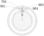
as shown in fig. 1, 2 and 3, the pressure roller speed measuring device 9 includes a pressure lever 901, the pressure lever 901 includes a connecting end 913 hinged to the outside of the inner spacer sleeve 8 and a movable end 902, a radial boss 701 is disposed on the inside of the outer spacer sleeve 7, when the outer spacer sleeve 7 rotates along with the pressure roller 4, the movable end 902 can be pressed down when the radial boss 701 rotates to the above of the pressure lever 901, a movably connected ejector pin 903 is further disposed in the inner spacer sleeve 8, specifically, a connecting hole is disposed on the inner spacer sleeve 8, the ejector pin 903 is mounted in the connecting hole and can move up and down in the connecting hole, the ejector pin 903 is mounted below the movable end 902, when the movable end 902 presses down, the ejector pin 903 is forced to press down, a cavity 906 is formed in a pressure roller shaft 5 at the lower end of the ejector pin 903, a connecting rod 907 is mounted in the cavity 906, the connecting rod 907 is disposed at the lower end of the ejector pin 903 and can move along with the pressing down of the ejector pin 903, the connecting rod 907 is configured to discharge air in the cavity 906 when pressing down, that the connecting rod 907 is configured to be hermetically disposed with the cavity 906.
Specifically, the outer circular surface of the lower end of the connecting rod 907 is adapted to the cavity 906 and is in contact with the inner wall of the cavity 906, in one embodiment, the lower end of the connecting rod 907 can be directly sleeved with a sealing ring or a sealing component such as a sealing strip, the contact part of the connecting rod 907 and the cavity 906 is sealed, of course, the connecting rod 907 can be installed by using the fixing sleeve 905 in order to obtain a better assembling and disassembling effect, specifically, the upper end of the cavity 906 is provided with a step table for installing the fixing sleeve 905, the upper end of the fixing sleeve 905 is provided with a protruding supporting part and is supported on the step table, and the connecting rod 907 is arranged in the fixing sleeve 905.
The lower end of the connecting rod 907 is provided with a second spring 910, the second spring 910 is mainly used for resetting the connecting rod 907, specifically, the bottom of the cavity 906 is provided with the second spring 910, the lower end of the connecting rod 907 is connected with the second spring 910, when the radial boss 701 in the outer spacer 7 rotates to the position above the movable end 902, the radial boss 701 can press down the movable end 902, the ejector pin 903 is pressed down by the movable end 902, the ejector pin 903 presses down the connecting rod 907, and when the radial boss 701 in the outer spacer 7 rotates to the position above the movable end 902, the second spring 910 rebounds and resets the connecting rod 907 and the ejector pin 903.
As shown in fig. 3, an air duct 914 is provided at the lower end of the cavity 906, the end of the air duct 914 is connected with a pressure detecting device and an air source, where the head end of the air duct 914 refers to the end connected with the cavity 906, and the end refers to the end away from the cavity 906, the end of the air duct 914 can be provided in the pressure roller shaft 5, and can be connected with an external air pipe through the pressure roller shaft 5, and the pressure detecting device here is not exclusive and can be a pressure gauge, a differential pressure gauge or other devices capable of responding to pressure changes, and the air source can be a device capable of generating external compressed air such as an air compressor, etc., and the air source is used for injecting suitable air into the air duct 914, so that pressure changes can be generated after the connecting rod 907 is pressed down.
The working principle is as follows: when the compression roller 4 rotates, the outer spacer 7 is driven to rotate, when the radial boss 701 rotates to the upper end of the movable end 902 of the compression bar 901, the movable end 902 is pressed down and drives the ejector pin 904 to press down, the ejector pin 904 presses down and drives the connecting rod 907 to press down, the air volume in the air channel 914 is reduced, the corresponding pressure is increased, the pressure detection device can reflect the change of the pressure in time, namely, whether the granulator is in a normal operation state or not can be seen, when the radial boss 701 rotates through the movable end 902 of the compression bar 901, the second spring 910 rebounds and pushes the connecting rod 907 and the ejector pin 904 to reset, the operation is repeated, and the rotating speed of the compression roller 4 can be calculated by counting the interval time of the pressure change.
In order to prolong the service life of the pressing rod 901 and the ejector pin 903, the movable end 902 of the pressing rod 901 is set as a rotating wheel, and the wheel surface of the rotating wheel is in contact with the upper end of the top surface of the ejector pin 903, so that sliding friction can be changed into rolling friction, the friction resistance is reduced, and the service life of the pressing rod is prolonged.
In order to obtain better resetting capability of the knock pin 903, the knock pin 903 comprises a press head 9031 and a press rod 9032, a boss (not shown in the figure) capable of placing the first spring 904 can be arranged at the upper end of the inner spacer sleeve 8, the first spring 904 is sleeved on the press rod 9032, the upper end of the first spring is abutted against the press head 9031, and the lower end of the first spring is arranged on the boss, namely when the outer spacer sleeve 7 is far away from the press rod 901, the knock pin 903 can obtain independent resetting capability.
For the convenience of installation and be convenient for detect more, this patent provides one kind and measures the concrete scheme of compression roller rotational speed through the differential pressure gauge change, as follows:
as shown in fig. 1, the air passage 914 is divided into a first air passage 911 and a second air passage 912, the first air passage 911 is opened in the pressure roller shaft 5, specifically, one end of the first air passage 911 is communicated with the cavity 906, the other end of the first air passage 911 passes through the pressure roller shaft 5 and is communicated with the second air passage 912 arranged in the spindle 4, one end of the spindle 4 exposed out of the granulator is an output end of the second air passage 912, and the first air passage 911 in the pressure roller shaft 5 can be communicated to the outside of the spindle 4 through the arrangement, so that the installation of the detection device is facilitated.
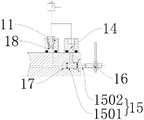
In an embodiment, a first air hole 18 and a second air hole 14 are formed in one end of the main shaft 4, where the main shaft 4 exposes out of the granulator, the first air hole 18 and the second air hole 14 are communicated with the second air channel 912, a check valve 11 is connected to the outside of the first air hole 18, an air source (not shown in the figure) continuously introduces compressed air into the first air hole 18 and the second air hole 14, the check valve 11 is used to prevent air in the second air channel 912 from flowing back through the first air hole 18, that is, a stable back pressure is always maintained at the first air hole 18, the check valve 11 is connected with the air source through an air pipe, a differential pressure gauge 13 is installed between the outside of the check valve 11 and the second air hole 14, when the connecting rod 907 is pressed down, the volume of the compressed air is reduced, the pressure at the first air hole 18 cannot be released due to the check valve 11, the pressure is concentrated at the second air hole 14, that the first air hole 18 is at a low pressure, the second air hole 14 is at a high pressure, the differential pressure meter 13 changes and sends an electric signal to and sends out an electric signal to and sends back to and forth to a related detection system, and then the pressure difference meter 13 can calculate the speed of the compression roller 4.
This patent still provides an utilize mode that proximity switch tested the speed, specifically as follows:
as shown in fig. 1, 5, and 6, a first air hole 18 and a second air hole 14 are formed at one end of the main shaft 4, where the first air hole 18 and the second air hole 14 are exposed, the first air hole 18 and the second air hole 912 are communicated with each other, a check valve 11 is connected to an outside of the first air hole 18, an air source (not shown in the figure) continuously introduces compressed air into the first air hole 18 and the second air hole 14, the check valve 11 is used to prevent air in the second air hole 912 from flowing back through the first air hole 18, that is, to ensure that a stable back pressure is always maintained at the first air hole 18, the check valve 11 is connected to the air source through an air pipe, the main shaft 3 is further provided with a guide hole 17, one end of the guide hole 17 is communicated with the first air hole 18 and the second air hole 912, the guide hole 17 is inserted with a detection rod 15, the detection rod 15 includes a sealing portion 1501 and a rod portion 1502, the sealing portion 1501 is connected to one end of the rod portion, the sealing portion 1501 is hermetically arranged with the guide hole 17, that the sealing portion 1501 is adapted to the guide hole 17 and can prevent air in the second air hole 912 from leaking, one side of the rod portion 1502 that is located near the second air hole 1502, and the detection rod portion 16 is located outside of the detection rod 1502, so that the detection rod 15 can be moved to push the detection rod 14, and thus the detection rod 15.
The working principle is as follows: when the link 907 is pressed down, the air pressure in the air channel 914 is changed, the detection rod 15 is pushed to move outwards, the proximity switch 16 can send out a signal after monitoring the position of the detection rod 15, and when the link 907 is reset, the detection rod 15 is reset by compressed air input from the second air hole 14, and the rotation speed of the compression roller 4 can be calculated by reciprocating.
In order to better realize the sealing effect of the connecting rod 907, a pressure plate 909 is arranged in the cavity 906 at the lower end of the connecting rod 907, a first sealing ring 908 is arranged between the pressure plate 909 and the connecting rod 907, the pressure plate 909 is matched with the cavity 908 and seals the cavity 908, and the pressure plate 909 can be pushed to press downwards after the connecting rod 907 is pressed downwards.
To ensure that the pressure supplied to the air passage 914 is controlled, a pressure regulating valve 12 is installed between the air supply and the check valve 11 and the second air vent 14.
The specific design of the device 9 for measuring the speed of the compression roller is described above, and in order to more clearly reflect the operating state of the granulator, the present application further provides a state monitoring method adapted to the above structure, which specifically comprises the following steps:
step 1: setting the normal running speed of the compression roller;
and 2, step: the method for measuring the rotating speed of the compression roller during the operation of the granulator in real time comprises the following steps:
the air source inputs compressed air into the first air passage and the second air passage;
feeding materials into the granulator;
after the material enters the granulator, rotating the annular die and lifting the material to a gap between the compression roller and the annular die by matching with the compression roller;
the compression roller rotates along with the lifting of the material and drives the outer spacer bush on the inner side of the compression roller to rotate, and when the outer spacer bush rotates to the upper end of the compression rod, the radial boss on the inner side of the outer spacer bush presses down the movable end of the compression rod;
the movable end of the pressure rod presses down a top pin arranged in the inner spacer sleeve, the top pin presses down a connecting rod under stress, and the connecting rod drives the pressure plate to press down and discharge air in the cavity, so that the air volumes in the first air passage and the second air passage are reduced;
one end of the differential pressure gauge connected with the second air hole is pressed to be changed into a high-pressure end, one end connected with the one-way valve is a low-pressure end, and the pressure of the differential pressure gauge is changed;
after the outer spacer sleeve rotates through the pressure rod, the connecting rod and the ejector pin respectively return to the initial positions by the rebounding force of the first spring and the second spring, the pressure returns to normal, the time interval of the change of the differential pressure gauge is calculated in a reciprocating mode, and the rotating speed of the compression roller is measured and calculated;
and 3, step 3: and comparing the measured rotating speed with the set rotating speed and outputting the operating state of the granulator.
According to the mode, the normal rotating speed is set in the controller in advance, the fed-back rotating speed of the granulator during normal operation is calculated through monitoring, then the rotating speed is compared with the normal rotating speed, the operating state of the granulator can be directly fed back, and whether the gap between the ring die and the compression roller needs to be adjusted or not can be known in time through the method.
This patent also provides another state monitoring method, which specifically includes:
step 1: setting the normal running speed of the compression roller;
and 2, step: the method for measuring the rotating speed of the compression roller during the operation of the granulator in real time comprises the following steps:
the air source inputs compressed air into the first air passage and the second air passage;
feeding materials into the granulator;
after the material enters the granulator, rotating the annular die and lifting the material to a gap between the compression roller and the annular die by matching with the compression roller;
the compression roller rotates along with the lifting of the material and drives the outer spacer bush on the inner side of the compression roller to rotate, and when the outer spacer bush rotates to the upper end of the compression rod, the radial boss on the inner side of the outer spacer bush presses down the movable end of the compression rod;
the movable end of the pressure lever presses down a top pin arranged in the inner spacer sleeve, the top pin presses down a connecting rod under stress, and the connecting rod drives the pressure plate to press down and discharge air in the cavity, so that the air volume in the first air passage and the second air passage is reduced;
one end of the detection rod connected with the second air passage is pressed and pushed outwards, and the outer side of the detection rod is connected with the proximity switch to detect the position of the detection rod and send a signal;
after the outer spacer sleeve rotates the compression bar, the connecting rod and the ejector pin respectively return to the initial position by the rebounding force of the first spring and the second spring, the pressure returns to normal, the closed part of the detection rod returns to the initial position by the pressure of the air source, the detection rod reciprocates and counts the time interval of the signal sending of the proximity switch, and the rotating speed of the compression roller is measured and calculated;
and step 3: and comparing the measured rotating speed with the set rotating speed and outputting the operating state of the granulator.
The difference between the scheme and the scheme is that the proximity switch is used for measuring and feeding back, and the state of the granulator can be monitored.
Although the present invention has been described in detail with reference to the foregoing embodiments, it will be apparent to those skilled in the art that various changes in the embodiments and/or modifications of the invention can be made, and equivalents and modifications of some features of the invention without departing from the spirit and scope of the invention.
Claims (8)
1. A granulation machine, characterized by comprising:
the ring die is rotatably arranged in the granulator and is provided with a plurality of discharge holes;
the compression roller shaft is arranged in the ring die and is sleeved with an outer spacer sleeve;
the compression roller is rotatably arranged on the compression roller shaft and is configured to drive the outer spacer bush to rotate, and the compression roller is used for matching with the annular die and pressing the material into the discharge port;
the compression roller speed measuring device is arranged between the compression roller shaft and the outer spacer sleeve and is configured to be used for measuring the rotating speed of the outer spacer sleeve driven by the compression roller, a first bearing and a second bearing are arranged on the compression roller shaft, the outer spacer sleeve is arranged between the first bearing and the second bearing and is clamped by the outer rings of the first bearing and the second bearing, and a radial boss is arranged on the inner side of the outer spacer sleeve;
still be equipped with interior spacer sleeve between first bearing with the second bearing, interior spacer sleeve configuration is pressed from both sides tightly by first bearing and the second bearing inner race, the compression roller speed sensor locate interior spacer sleeve with on the compression roller axle, and include:
the air passage penetrates through the compression roller shaft, and the head end of the air passage is communicated with a cavity formed in the compression roller shaft;
the air source is communicated with the air passage and continuously supplies compressed air into the air passage;
the connecting end is rotatably arranged on the outer side of the inner spacer bush and is configured to press down the movable end when the radial boss rotates to a position above the compression rod along with the rotation of the outer spacer bush;
the knock pin, the knock pin is located movable end below and mobilizable cross-under in separate the cover, just, the knock pin includes:
the pressure head is movably connected in the inner spacer sleeve and is used for contacting with the movable end when rotating to the position above the pressure rod with the outer spacer sleeve;
one end of the pressing rod is connected to the lower end of the pressing head, and the other end of the pressing rod is abutted to the upper end of the connecting rod;
a second spring is further arranged in the inner spacer sleeve and is sleeved on the abutting rod and abutted against the lower end of the pressure head; the connecting rod is positioned at the lower end of the ejector pin and movably arranged in the cavity, a first spring is arranged at the lower end of the connecting rod, and the connecting rod is configured to force the air volume in the air passage to be reduced when the connecting rod is pressed down;
a pressure detection device in communication with the airway end for detecting a change in pressure within the airway caused by depression of the linkage.
2. The granulation machine of claim 1, the air channel comprising:
the first air passage is arranged in the compression roller shaft, and the second air passage is arranged in the main shaft for fixing the compression roller shaft;
the first air passage is communicated with the second air passage, the main shaft is provided with a first air hole and a second air hole which are both communicated with the second air passage, and the first air hole and the second air hole are communicated with the air source;
first gas pocket with be connected with the check valve through the trachea between the air supply, the check valve be used for continuously with the compressed air that the air supply provided is leading-in extremely in the second air flue, the second gas pocket with be connected with the differential pressure gauge between the external trachea of check valve, the differential pressure gauge is used for detecting the differential pressure change of second gas pocket.
3. The granulation machine of claim 1, the air channel comprising:
the first air passage is arranged in the compression roller shaft, and the second air passage is arranged in the main shaft for fixing the compression roller shaft;
the first air passage is communicated with the second air passage, the main shaft is provided with a first air hole, a second air hole and a guide hole, the first air hole is communicated with the second air passage, one end of the guide hole is communicated with the second air passage and the first air hole, and a detection rod is inserted in the guide hole;
detect the pole include the closing part and with the pole portion that closing part one end is connected, the closing part adaptation in the guiding hole will the guiding hole is sealed, pole portion is located one side of guiding hole with second gas pocket intercommunication, be connected with the check valve through the trachea between the air supply, the check valve be used for lasting with the compressed air that the air supply provided is leading-in extremely in the second air flue, along proximity switch is still installed in the outside that pole portion length direction extends, proximity switch is used for detecting pole portion approximate position.
4. The granulation machine according to claim 1, wherein the movable end is provided with a rotating wheel through a pin shaft, and the wheel surface of the rotating wheel is in contact with the pressure head.
5. The granulation machine as claimed in claim 1, wherein a pressing plate is installed at a lower end of the connecting rod, the pressing plate is installed above the first spring, a first sealing ring is installed between the pressing plate and the connecting rod, and the pressing plate is adapted to the cavity and seals the cavity.
6. The granulation machine according to claim 2 or 3, wherein a pressure regulating valve is connected to the outside of the one-way valve through a gas pipe for regulating the input pressure of the gas source into the second gas passage.
7. A method for monitoring the running state of a granulator is characterized in that: the granulation machine as defined in claim 2 and comprising the steps of:
step 1: setting the normal running rotating speed of the compression roller;
step 2: the method for measuring the rotating speed of the compression roller during the operation of the granulator in real time comprises the step of measuring the rotating speed of the compression roller by using a compression roller speed measuring device arranged between a compression roller shaft and an outer spacer bush, and specifically comprises the step of measuring the rotating speed of the compression roller by using the compression roller speed measuring device
The air source introduces compressed air into an air passage penetrating through the compression roller shaft, the air passage comprises a first air passage and a second air passage communicated with the first air passage, the first air passage is arranged in the compression roller shaft, the second air passage is arranged in a main shaft for fixing the compression roller shaft, and the air source inputs the compressed air into the first air passage and the second air passage respectively;
feeding materials into the granulator;
after the material enters the granulator, rotating the ring die and matching with a compression roller to lift the material to a gap between the compression roller and the ring die;
the compression roller rotates along with the lifting of the material and drives the outer spacer bush on the inner side of the compression roller to rotate, and when the outer spacer bush rotates to the upper end of the compression rod, the radial boss on the inner side of the outer spacer bush presses down the movable end of the compression rod;
the movable end of the pressure rod presses down a top pin arranged in the inner spacer sleeve, the top pin presses down a connecting rod under stress, and the connecting rod drives the pressure plate to press down and discharge air in the cavity, so that the air volumes in the first air passage and the second air passage are reduced;
one end of the differential pressure gauge connected with the second air hole is pressed to be changed into a high-pressure end, one end connected with the one-way valve is a low-pressure end, and the pressure of the differential pressure gauge is changed;
after the outer spacer sleeve rotates through the pressure rod, the connecting rod and the ejector pin respectively return to the initial positions by the rebounding force of the first spring and the second spring, the pressure returns to normal, the time interval of the change of the differential pressure gauge is calculated in a reciprocating mode, and the rotating speed of the compression roller is measured and calculated;
and step 3: and comparing the measured rotating speed with the set rotating speed and outputting the operating state of the granulator.
8. A method for monitoring the running state of a granulator is characterized in that: the granulation machine as claimed in claim 3, and comprising the steps of:
step 1: setting the normal running speed of the compression roller;
step 2: the method for measuring the rotating speed of the compression roller during the operation of the granulator in real time comprises the steps of measuring the rotating speed of the compression roller by using a compression roller speed measuring device arranged between a compression roller shaft and an outer spacer sleeve, and specifically comprises the following steps:
the air source introduces compressed air into an air passage penetrating through the compression roller shaft, the air passage comprises a first air passage and a second air passage communicated with the first air passage, the first air passage is arranged in the compression roller shaft, the second air passage is arranged in a main shaft for fixing the compression roller shaft, and the air source inputs the compressed air into the first air passage and the second air passage respectively;
feeding materials into the granulator;
after the material enters the granulator, rotating the ring die and matching with a compression roller to lift the material to a gap between the compression roller and the ring die;
the compression roller rotates along with the lifting of the material and drives the outer spacer bush on the inner side of the compression roller to rotate, and when the outer spacer bush rotates to the upper end of the compression rod, the radial boss on the inner side of the outer spacer bush presses down the movable end of the compression rod;
the movable end of the pressure rod presses down a top pin arranged in the inner spacer sleeve, the top pin presses down a connecting rod under stress, and the connecting rod drives the pressure plate to press down and discharge air in the cavity, so that the air volumes in the first air passage and the second air passage are reduced;
one end of the detection rod connected with the second air passage is pressed and pushed outwards, and the outer side of the detection rod is connected with the proximity switch to detect the position of the detection rod and send a signal;
after the outer spacer sleeve rotates the compression bar, the connecting rod and the ejector pin respectively return to the initial position by the rebounding force of the first spring and the second spring, the pressure returns to normal, the closed part of the detection rod returns to the initial position by the pressure of the air source, the detection rod reciprocates and counts the time interval of the signal sending of the proximity switch, and the rotating speed of the compression roller is measured and calculated;
and 3, step 3: and comparing the measured rotating speed with the set rotating speed and outputting the operating state of the granulator.
Priority Applications (1)
| Application Number | Priority Date | Filing Date | Title |
|---|---|---|---|
| CN202210025203.0A CN114432963B (en) | 2022-01-11 | 2022-01-11 | Granulation machine and running state monitoring method thereof |
Applications Claiming Priority (1)
| Application Number | Priority Date | Filing Date | Title |
|---|---|---|---|
| CN202210025203.0A CN114432963B (en) | 2022-01-11 | 2022-01-11 | Granulation machine and running state monitoring method thereof |
Publications (2)
| Publication Number | Publication Date |
|---|---|
| CN114432963A CN114432963A (en) | 2022-05-06 |
| CN114432963B true CN114432963B (en) | 2022-12-27 |
Family
ID=81368476
Family Applications (1)
| Application Number | Title | Priority Date | Filing Date |
|---|---|---|---|
| CN202210025203.0A Active CN114432963B (en) | 2022-01-11 | 2022-01-11 | Granulation machine and running state monitoring method thereof |
Country Status (1)
| Country | Link |
|---|---|
| CN (1) | CN114432963B (en) |
Citations (16)
| Publication number | Priority date | Publication date | Assignee | Title |
|---|---|---|---|---|
| US2966699A (en) * | 1955-10-17 | 1961-01-03 | Coal Industry Patents Ltd | Ring roll presses |
| EP0231764B1 (en) * | 1986-01-24 | 1991-12-27 | Bühler Ag | Pellet press |
| JPH0932717A (en) * | 1995-07-24 | 1997-02-04 | Eizaburo Murakami | Pressure-machine converter |
| JPH11169701A (en) * | 1997-12-08 | 1999-06-29 | Fulta Electric Machinery Co Ltd | Granulating machine |
| WO2010020382A2 (en) * | 2008-08-20 | 2010-02-25 | Eduard Schwarz | Compression roll arrangement, and compression roll |
| CN201454494U (en) * | 2009-08-06 | 2010-05-12 | 上海申德机械有限公司 | Novel granulator of biomass or refuse derived fuel particles |
| CN102631866A (en) * | 2012-05-09 | 2012-08-15 | 中国农业大学 | Moving roller-type circular mould granulator |
| JP2013043109A (en) * | 2011-08-23 | 2013-03-04 | Daio Engineering Co Ltd | Pellet production apparatus |
| CN204320235U (en) * | 2014-11-19 | 2015-05-13 | 常州远见机械有限公司 | Ring mould fixed type biological matter granulator |
| JP2015173994A (en) * | 2014-03-13 | 2015-10-05 | Jfeスチール株式会社 | Ring die granulator |
| CN106140013A (en) * | 2015-05-27 | 2016-11-23 | 东莞市圣珂新能源环保科技有限公司 | Biomass horizontal ring dies granulation mechanism |
| CN109900919A (en) * | 2019-03-13 | 2019-06-18 | 北京强度环境研究所 | A kind of sharp vibration-measuring sensor that tests the speed in column whirlpool |
| CN209034483U (en) * | 2018-09-05 | 2019-06-28 | 保定市新东远机械设备制造有限公司 | Roll band pelleter |
| CN110280187A (en) * | 2019-08-06 | 2019-09-27 | 安徽环态生物能源科技开发有限公司 | A kind of biomass granulation machine of ring moulds roller structure bilateral discharging |
| CN111733677A (en) * | 2020-07-10 | 2020-10-02 | 何大安 | Pitch is filled pit road construction compression roller assembly |
| CN213348784U (en) * | 2020-09-25 | 2021-06-04 | 广东晨之兴科技有限公司 | Horizontal ring die granulation machine |
Family Cites Families (1)
| Publication number | Priority date | Publication date | Assignee | Title |
|---|---|---|---|---|
| DE102015205642A1 (en) * | 2015-03-10 | 2016-09-15 | Alexanderwerk Gmbh | Apparatus for producing a granulate |
-
2022
- 2022-01-11 CN CN202210025203.0A patent/CN114432963B/en active Active
Patent Citations (16)
| Publication number | Priority date | Publication date | Assignee | Title |
|---|---|---|---|---|
| US2966699A (en) * | 1955-10-17 | 1961-01-03 | Coal Industry Patents Ltd | Ring roll presses |
| EP0231764B1 (en) * | 1986-01-24 | 1991-12-27 | Bühler Ag | Pellet press |
| JPH0932717A (en) * | 1995-07-24 | 1997-02-04 | Eizaburo Murakami | Pressure-machine converter |
| JPH11169701A (en) * | 1997-12-08 | 1999-06-29 | Fulta Electric Machinery Co Ltd | Granulating machine |
| WO2010020382A2 (en) * | 2008-08-20 | 2010-02-25 | Eduard Schwarz | Compression roll arrangement, and compression roll |
| CN201454494U (en) * | 2009-08-06 | 2010-05-12 | 上海申德机械有限公司 | Novel granulator of biomass or refuse derived fuel particles |
| JP2013043109A (en) * | 2011-08-23 | 2013-03-04 | Daio Engineering Co Ltd | Pellet production apparatus |
| CN102631866A (en) * | 2012-05-09 | 2012-08-15 | 中国农业大学 | Moving roller-type circular mould granulator |
| JP2015173994A (en) * | 2014-03-13 | 2015-10-05 | Jfeスチール株式会社 | Ring die granulator |
| CN204320235U (en) * | 2014-11-19 | 2015-05-13 | 常州远见机械有限公司 | Ring mould fixed type biological matter granulator |
| CN106140013A (en) * | 2015-05-27 | 2016-11-23 | 东莞市圣珂新能源环保科技有限公司 | Biomass horizontal ring dies granulation mechanism |
| CN209034483U (en) * | 2018-09-05 | 2019-06-28 | 保定市新东远机械设备制造有限公司 | Roll band pelleter |
| CN109900919A (en) * | 2019-03-13 | 2019-06-18 | 北京强度环境研究所 | A kind of sharp vibration-measuring sensor that tests the speed in column whirlpool |
| CN110280187A (en) * | 2019-08-06 | 2019-09-27 | 安徽环态生物能源科技开发有限公司 | A kind of biomass granulation machine of ring moulds roller structure bilateral discharging |
| CN111733677A (en) * | 2020-07-10 | 2020-10-02 | 何大安 | Pitch is filled pit road construction compression roller assembly |
| CN213348784U (en) * | 2020-09-25 | 2021-06-04 | 广东晨之兴科技有限公司 | Horizontal ring die granulation machine |
Also Published As
| Publication number | Publication date |
|---|---|
| CN114432963A (en) | 2022-05-06 |
Similar Documents
| Publication | Publication Date | Title |
|---|---|---|
| CN201302506Y (en) | Oil seal air-tightness detection device | |
| CN114432963B (en) | Granulation machine and running state monitoring method thereof | |
| CN105136356A (en) | Testing machine of interface pressure of cable accessory | |
| CN114486082B (en) | Air tightness detection device of turbocharger shell | |
| CN109612615A (en) | The test device of automobile hub bearing load friction torque | |
| CN105716880A (en) | Dynamic calibration device of roller counterforce type brake inspection table and calibration method of dynamic calibration device | |
| CN202582890U (en) | Air valve testing jig | |
| CN111323174B (en) | System and method for detecting tire after manufacturing and molding | |
| CN114199555A (en) | Top dead center testing equipment and testing method thereof | |
| CN211291841U (en) | O-shaped ring sliding friction force measuring device | |
| CN220104429U (en) | Rotary kiln sealing device inspection platform | |
| CN220470186U (en) | Measurement tool for magnetic drive pump operation test | |
| CN220735390U (en) | Sphygmomanometer verification calibrating device | |
| CN217276038U (en) | Measuring device for tubular objects | |
| CN114838678B (en) | Pneumatic measuring device for outer diameter of thin-wall bearing ring | |
| CN220206650U (en) | Online play detection device of hub unit | |
| CN212180514U (en) | Slidingtype cigarette hardness measuring device | |
| CN108489726B (en) | Durability detection device for gas pressure regulator membrane | |
| CN218973734U (en) | Air tightness detection device for faucet shell | |
| CN216483931U (en) | Upper dead center test equipment | |
| CN110296826B (en) | Inflation valve detection device | |
| CN219503255U (en) | Device for efficiently judging size of bearing | |
| CN218646539U (en) | Servo spinning air tightness detection device applied to paddle board | |
| CN211262556U (en) | Device capable of automatically and manually detecting segmentation unit | |
| CN213422612U (en) | Lubricating grease measuring device in bearing and intelligent bearing grease changing system |
Legal Events
| Date | Code | Title | Description |
|---|---|---|---|
| PB01 | Publication | ||
| PB01 | Publication | ||
| SE01 | Entry into force of request for substantive examination | ||
| SE01 | Entry into force of request for substantive examination | ||
| GR01 | Patent grant | ||
| GR01 | Patent grant |