CN114423261B - Water-cooling circulating type intelligent cabin domain heat dissipation system - Google Patents
Water-cooling circulating type intelligent cabin domain heat dissipation system Download PDFInfo
- Publication number
- CN114423261B CN114423261B CN202210308553.8A CN202210308553A CN114423261B CN 114423261 B CN114423261 B CN 114423261B CN 202210308553 A CN202210308553 A CN 202210308553A CN 114423261 B CN114423261 B CN 114423261B
- Authority
- CN
- China
- Prior art keywords
- water
- circuit board
- heat dissipation
- plate
- type intelligent
- Prior art date
- Legal status (The legal status is an assumption and is not a legal conclusion. Google has not performed a legal analysis and makes no representation as to the accuracy of the status listed.)
- Active
Links
Images


Classifications
-
- H—ELECTRICITY
- H05—ELECTRIC TECHNIQUES NOT OTHERWISE PROVIDED FOR
- H05K—PRINTED CIRCUITS; CASINGS OR CONSTRUCTIONAL DETAILS OF ELECTRIC APPARATUS; MANUFACTURE OF ASSEMBLAGES OF ELECTRICAL COMPONENTS
- H05K7/00—Constructional details common to different types of electric apparatus
- H05K7/20—Modifications to facilitate cooling, ventilating, or heating
- H05K7/20845—Modifications to facilitate cooling, ventilating, or heating for automotive electronic casings
- H05K7/20872—Liquid coolant without phase change
-
- H—ELECTRICITY
- H05—ELECTRIC TECHNIQUES NOT OTHERWISE PROVIDED FOR
- H05K—PRINTED CIRCUITS; CASINGS OR CONSTRUCTIONAL DETAILS OF ELECTRIC APPARATUS; MANUFACTURE OF ASSEMBLAGES OF ELECTRICAL COMPONENTS
- H05K1/00—Printed circuits
- H05K1/02—Details
- H05K1/0201—Thermal arrangements, e.g. for cooling, heating or preventing overheating
- H05K1/0203—Cooling of mounted components
-
- Y—GENERAL TAGGING OF NEW TECHNOLOGICAL DEVELOPMENTS; GENERAL TAGGING OF CROSS-SECTIONAL TECHNOLOGIES SPANNING OVER SEVERAL SECTIONS OF THE IPC; TECHNICAL SUBJECTS COVERED BY FORMER USPC CROSS-REFERENCE ART COLLECTIONS [XRACs] AND DIGESTS
- Y02—TECHNOLOGIES OR APPLICATIONS FOR MITIGATION OR ADAPTATION AGAINST CLIMATE CHANGE
- Y02T—CLIMATE CHANGE MITIGATION TECHNOLOGIES RELATED TO TRANSPORTATION
- Y02T10/00—Road transport of goods or passengers
- Y02T10/80—Technologies aiming to reduce greenhouse gasses emissions common to all road transportation technologies
- Y02T10/88—Optimized components or subsystems, e.g. lighting, actively controlled glasses
Abstract
The invention belongs to the technical field of vehicle-mounted intelligent cabin domain hosts, and particularly relates to a water-cooling circulation type intelligent cabin domain heat dissipation system which comprises a first circuit board, wherein a second circuit board is arranged at the bottom of the first circuit board, a middle frame is arranged between the first circuit board and the second circuit board, an upper cover is arranged at the top of the first circuit board, and a lower cover is arranged at the bottom of the second circuit board. According to the invention, the heat dissipation device is arranged, when water in a vehicle water system is filled in the space corresponding to the partition plate, heat generated by the first circuit board and the second circuit board can be absorbed by the water in the space of the partition plate, then the water enters the backflow box through the one-way valve and finally returns to the water system of the vehicle through the water outlet pipe, so that the purpose of cooling the host is achieved, in addition, the blade plate arranged on the partition plate can absorb kinetic energy of the water flow, so that the speed of the water flow is reduced, the retention time of the water flow is prolonged, and the heat dissipation effect of the water flow on the first circuit board and the second circuit board is further improved.
Description
Technical Field
The invention belongs to the technical field of vehicle-mounted intelligent cabin hosts, and particularly relates to a water-cooling circulation type intelligent cabin domain heat dissipation system.
Background
The vehicle-mounted intelligent cabin domain host computer is a special vehicle informationized product which is developed specially for special running environment of vehicle and electric circuit characteristics and can be combined with electronic circuit of vehicle, and is a high-integrated vehicle multimedia entertainment information centre, and can be used for centrally controlling various equipments of navigation, music, video and audio equipment, game and telephone equipment, etc. in the vehicle.
Because the consumption of on-vehicle intelligent passenger cabin territory host computer is great, consequently on-vehicle multimedia can produce a lot of heats in the use, and current on-vehicle host computer dispels the heat to the host computer through the fin of installing on the shell mostly, and consequently the radiating effect is not good, and current host computer is when the heat dissipation in addition, and the heat that the host computer produced collects easily in the casing, and difficult the discharge influences the radiating efficiency of host computer equally.
Therefore, it is necessary to provide a water-cooling circulation type intelligent cabin area heat dissipation system to solve the above problems.
Disclosure of Invention
In view of the above problems, the present invention provides a water-cooling circulation type intelligent cabin area heat dissipation system to solve the problems proposed in the background art.
In order to achieve the purpose, the invention provides the following technical scheme: the utility model provides a circulating intelligent passenger cabin territory cooling system of water-cooling, includes first circuit board, the bottom of first circuit board is equipped with the second circuit board, be equipped with the center between first circuit board and the second circuit board, the top of first circuit board is equipped with the upper cover, the bottom of second circuit board is equipped with the lower cover, and upper cover and lower cover all are connected with the center, the antenna is installed at the top of upper cover, and the antenna passes through wire and first circuit board electric connection, the center inboard is equipped with heat abstractor.
Further, the heat dissipation device comprises a water cooling tank, the water cooling tank is fixedly connected with the inner side of the middle frame, a sealing cover is installed at the top of the water cooling tank, two partition plates are horizontally and fixedly connected with the inner side of the water cooling tank, a return tank is arranged between the two partition plates, the return tank is fixedly connected with the inner wall of the water cooling tank, a guide pipe is connected between the space on one side, away from the two partition plates, of the two partition plates and the return tank, a one-way valve is installed at one end, located in the return tank, of the guide pipe, a water inlet pipe and a water outlet pipe are inserted in the front side of the water cooling tank in a penetrating manner, the water inlet pipe and the water outlet pipe are both connected with the water system of the vehicle through valves, the rear end of the water outlet pipe is communicated with the return tank, the rear end of the water inlet pipe is in a sealing design, the top and the bottom of the water inlet pipe are both connected with connecting pipes, the two connecting pipes are respectively and vertically inserted in the two partition plates in a penetrating manner, one end, away from each connecting pipe, is vertically connected with a main pipe, the rear side of house steward is connected with a plurality of branch pipes perpendicularly, two the baffle is all rotated on the one side of separating and is connected with multiseriate pivot, multiseriate pivot and a plurality of branch pipe one-to-one, and the branch pipe corresponds with one side of pivot, a plurality of lamina of side fixedly connected with of pivot, adjacent two are listed as and are equipped with the baffle between the pivot, and baffle fixed connection.
Furthermore, the free end of the blade plate is slidably inserted with a movable plate, a strip-shaped groove is formed in the bottom of the blade plate in a penetrating mode, the driving rod is fixedly connected to the bottom of the movable plate and penetrates through the strip-shaped groove, an elliptic groove is formed in the partition plate corresponding to the periphery of the rotating shaft, a connecting line between two far ends of the elliptic groove is parallel to the front side of the water cooling box, the center of the elliptic groove coincides with the circle center of the rotating shaft, and the bottoms of all the driving rods on the same rotating shaft are located in the elliptic groove.
Furthermore, a first hole is formed in the movable plate in a penetrating mode, a second hole is formed in the blade plate in a penetrating mode, the width of the second hole is half of that of the first hole, the maximum distance between the first hole and the second hole on the same side is equal to the maximum distance of the movable plate moving along the elliptical groove, and the first hole is located inside the blade plate all the time.
Further, the rear side of pivot is equipped with the guide plate, and the guide plate is located this pivot and keeps away from one side of corresponding branch pipe, guide plate and baffle fixed connection, and the guide plate from going to the direction slope of keeping away from the pivot after.
Further, the radiating holes are formed in the two sides of the upper cover, the lower cover and the middle frame, and dust screens are installed in the radiating holes.
Further, the top of upper cover and the bottom of lower cover all fixedly connected with a plurality of heat dissipation laths, and a plurality of heat dissipation laths are evenly distributed.
Furthermore, a plurality of radiating pipes are inserted in the two sides of the water cooling tank in a penetrating mode, one ends, located in the water cooling tank, of the radiating pipes are designed in a sealing mode, and the other ends of the radiating pipes are communicated with the outside.
Furthermore, a gap exists between the partition plate and the return box, and the gap is filled with heat insulation cotton.
Furthermore, the opposite side of the first circuit board and the opposite side of the second circuit board are fixedly connected with heat dissipation bosses, annular enclosing plates are fixedly connected to the tops of the sealing covers or the bottoms of the water cooling boxes in the corresponding areas of the heat dissipation bosses, the annular enclosing plates are matched with the areas where the heat dissipation bosses are located, and heat conduction gel is filled between the heat dissipation bosses and the annular enclosing plates.
The invention has the technical effects and advantages that:
1. according to the invention, the heat dissipation system is arranged, when water in a vehicle water system enters the water cooling tank, water flow gradually fills the space corresponding to the partition plate, at the moment, heat generated by the first circuit board and the second circuit board can be absorbed by the water in the space of the partition plate, then the water absorbing the heat enters the backflow tank through the one-way valve, and the water in the backflow tank can finally return to the vehicle water system through the water outlet pipe, so that the purpose of cooling a host machine is achieved;
2. in the process of rotation of the blade plate, when the deflector rod moves from the near end to the far end of the elliptical groove, the movable plate gradually moves towards the direction far away from the rotating shaft, the movable plate is gradually close to the baffle, the first strip hole and the second strip hole are staggered, so that the space on the front side and the rear side of the rotating shaft can be gradually separated by the movable plate and the blade plate, the mutual influence between the water temperatures around two adjacent rotating shafts is further reduced, when the deflector rod moves from the far end to the near end of the elliptical groove, the movable plate gradually enters the blade plate, the resistance of the blade plate to water flow is reduced, in addition, the first strip hole and the second strip hole are gradually overlapped as the movable plate continuously enters the blade plate, the water flow can penetrate through the blade plate through the movable plate and the blade plate, the resistance of the blade plate in the rotation process is further reduced, and the rotation efficiency of the rotating shaft is ensured.
Additional features and advantages of the invention will be set forth in the description which follows, and in part will be obvious from the description, or may be learned by practice of the invention. The objectives and other advantages of the invention will be realized and attained by the structure particularly pointed out in the written description and drawings.
Drawings
In order to more clearly illustrate the embodiments of the present invention or the technical solutions in the prior art, the drawings used in the description of the embodiments or the prior art will be briefly described below, and it is obvious that the drawings in the following description are some embodiments of the present invention, and those skilled in the art can also obtain other drawings according to the drawings without creative efforts.
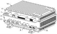
FIG. 1 is a first perspective view of the present invention;
FIG. 2 is a second perspective view of the present invention;
FIG. 3 is a schematic perspective view of a first circuit board, a second circuit board and a middle frame according to the present invention;
FIG. 4 is a first perspective view of the heat dissipation device of the present invention;
FIG. 5 is a schematic diagram of a second perspective structure of the heat dissipation device of the present invention;
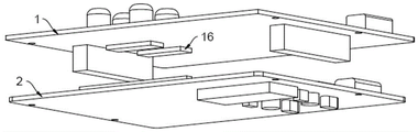
FIG. 6 is a schematic diagram of a first perspective structure of a first circuit board and a second circuit board according to the present invention;
FIG. 7 is a second perspective view of the first circuit board and the second circuit board of the present invention;
FIG. 8 is a schematic view of the internal structure of the heat dissipation device of the present invention;
FIG. 9 is a schematic perspective view of the baffle plate and the return box of the present invention;
FIG. 10 is a first perspective view of a separator plate according to the present invention;
FIG. 11 is an enlarged view of portion A of FIG. 10 according to the present invention;
fig. 12 is a second perspective view of the separator of the present invention.
In the figure: 1. a first circuit board; 2. a second circuit board; 3. a middle frame; 4. an upper cover; 5. a lower cover; 6. a heat sink; 601. a water cooling tank; 602. a sealing cover; 603. a partition plate; 604. a return tank; 605. a one-way valve; 606. a water inlet pipe; 607. a water outlet pipe; 608. connecting pipes; 609. a header pipe; 610. a branch pipe; 611. a rotating shaft; 612. a leaf plate; 613. a baffle plate; 7. a movable plate; 8. a deflector rod; 9. an elliptical slot; 10. a first aperture; 11. a second aperture; 12. a baffle; 13. a dust screen; 14. a heat dissipation strip plate; 15. a radiating pipe; 16. a heat dissipation boss; 17. an annular shroud.
Detailed Description
In order to make the objects, technical solutions and advantages of the embodiments of the present invention clearer, the technical solutions in the embodiments of the present invention will be clearly and completely described below with reference to the drawings in the embodiments of the present invention, and it is obvious that the described embodiments are some, but not all, embodiments of the present invention. All other embodiments, which can be obtained by a person skilled in the art without making any creative effort based on the embodiments in the present invention, belong to the protection scope of the present invention.
The invention provides a water-cooling circulation type intelligent cabin area heat dissipation system as shown in figures 1-12, which can be used as a vehicle-mounted host, and comprises a first circuit board 1, wherein a second circuit board 2 is arranged at the bottom of the first circuit board 1, a middle frame 3 is arranged between the first circuit board 1 and the second circuit board 2, an upper cover 4 is arranged at the top of the first circuit board 1, a lower cover 5 is arranged at the bottom of the second circuit board 2, the upper cover 4 and the lower cover 5 are both connected with the middle frame 3 through screws, an antenna is arranged at the top of the upper cover 4 and is electrically connected with the first circuit board 1 through a lead, a heat dissipation device 6 is arranged at the inner side of the middle frame 3, a heat dissipation boss 16 is fixedly connected at one side of the first circuit board 1 opposite to the second circuit board 2, an annular baffle 17 is fixedly connected at the top of a sealing cover 602 in the region corresponding to the heat dissipation boss 16 or at the bottom of a water-cooling tank 601, the annular enclosing plate 17 is matched with the area where the heat dissipation boss 16 is located, heat conduction gel is filled between the heat dissipation boss 16 and the annular enclosing plate 17, the top of the upper cover 4 and the bottom of the lower cover 5 are fixedly connected with a plurality of heat dissipation strips 14, the plurality of heat dissipation strips 14 are uniformly distributed, heat dissipation holes are formed in the upper cover 4, the lower cover 5 and the two sides of the middle frame 3, and dust screens 13 are installed in the heat dissipation holes;
before the host is used, heat-conducting gel is coated on the heat-radiating bulges on the first circuit board 1 and the second circuit board 2, then all the parts are assembled according to the mode of figure 1, and after the assembly is finished, the heat-radiating device 6 is connected with a water system of a vehicle;
in the use process of the host, when the first circuit board 1 and the second circuit board 2 generate heat, the first circuit board 1 and the second circuit board respectively transfer most of the heat generated by the first circuit board 1 and the second circuit board to the heat dissipation device 6 through the corresponding heat dissipation bosses 16, and finally the heat transferred to the heat dissipation device 6 can be taken away through a water system of a vehicle, so that the purpose of dissipating the heat of the first circuit board 1 and the second circuit board 2 is achieved;
in addition, a part of heat generated from the first circuit board 1 and the second circuit board is transferred to the upper cover 4 and the lower cover 5, and the heat on the upper cover 4 and the lower cover 5 can be rapidly diffused to the outside air through the heat dissipation strip 14, thereby improving the heat dissipation performance of the host.
As shown in fig. 2 to 12, the heat dissipation device 6 includes a water cooling tank 601, the water cooling tank 601 is fixedly connected to the inner side of the middle frame 3, a sealing cover 602 is installed on the top of the water cooling tank 601, two partition plates 603 are horizontally and fixedly connected to the inner side of the water cooling tank 601, a return tank 604 is disposed between the two partition plates 603, the return tank 604 is fixedly connected to the inner wall of the water cooling tank 601, a conduit is connected between the space on the side where the two partition plates 603 are away from each other and the return tank 604, a one-way valve 605 is installed at one end of the conduit located in the return tank 604, a water inlet pipe 606 and a water outlet pipe 607 are inserted into the front side of the water cooling tank 601, the water inlet pipe 606 and the water outlet pipe 607 are both connected to the water system of the vehicle through a valve, the rear end of the water outlet pipe 607 is communicated with the return tank 604, the rear end of the water inlet pipe 606 is of a sealing design, and the top and the bottom of the water inlet pipe 606 are both connected to a connecting pipe 608, the two connecting pipes 608 respectively penetrate and are inserted in the two partition plates 603 in a vertical penetrating manner, one end of each of the two connecting pipes 608, which is away from each other, is vertically connected with a main pipe 609, the rear side of the main pipe 609 is vertically connected with a plurality of branch pipes 610, one side of each of the two partition plates 603, which is away from each other, is rotatably connected with a plurality of rows of rotating shafts 611, the plurality of rows of rotating shafts 611 correspond to the plurality of branch pipes 610 one by one, the branch pipes 610 correspond to one side of the rotating shafts 611, the side surface of each rotating shaft 611 is fixedly connected with a plurality of blades 612, a baffle 613 is arranged between each two adjacent rows of rotating shafts 611, the baffle 613 is fixedly connected with the partition plates 603, a gap is formed between each partition plate 603 and the return box 604, heat insulation cotton is filled in the gap, a plurality of radiating pipes 15 are inserted in the two sides of the water cooling box 601 in a penetrating manner, one end of each radiating pipe 15, which is located in the water cooling box 601, is designed in a sealed manner, and the other end of each radiating pipe 15 is communicated with the outside;
when the heat of the first circuit board 1 and the second circuit board 2 is transferred to the water cooling tank 601, along with the operation of the water system of the vehicle, at this time, cold water in the vehicle can enter the space on the side where the two clapboards 603 are separated from each other through the water inlet pipe 606, at this time, the heat generated by the first circuit board 1 and the second circuit board 2 can be absorbed by the water in the space, along with the continuous increase of the water level in the space, when the space is filled with cold water, the one-way valve 605 is opened due to the pressure, at this time, the water flow absorbing the heat can enter the return tank 604 through the one-way valve 605, because the heat insulation cotton is filled between the return tank 604 and the clapboards 603, the temperature of the water in the return tank 604 can not affect the temperature of the water in the space on the side where the two clapboards 603 are separated from each other, thereby improving the heat dissipation effect of the water in the space on the first circuit board 1 and the second circuit board 2 on the two clapboards 603, the water in the return tank 604 can finally return to a water system of the vehicle through the water outlet pipe 607, so that the purpose of cooling the host is achieved;
in addition, because the partition 603 is provided with the rotating shaft 611 and the blades 612, when water in the main pipe 609 impacts the blades 612 through the branch pipes 610, the blades 612 drive the rotating shaft 611 to rotate under the pushing of the water flow, so that the water near the rotating shaft 611 can be stirred under the action of the blades 612, and further the water temperature near the rotating shaft 611 can be more uniform, meanwhile, due to the blocking effect of the blades 612, part of kinetic energy of the water flow is consumed by the blades 612, the speed of the water flow is reduced, the stay time of the water flow is prolonged, further, heat generated by the first circuit board 1 and the second circuit board 2 can be absorbed by the water flow as much as possible, and the heat dissipation effect of the water flow on the first circuit board 1 and the second circuit board 2 is improved;
due to the heat dissipation pipe 15, after the water flow absorbs heat, part of the heat in the water can be dissipated to the outside through the heat dissipation pipe 15, so that the temperature of the water in the space corresponding to the partition plate 603 is reduced, and the water in the space can absorb more heat conveniently.
As shown in fig. 8-11, a movable plate 7 is slidably inserted into a free end of the vane 612, a strip-shaped groove is formed through the bottom of the vane 612, a shift lever 8 is fixedly connected to the bottom of the movable plate 7, the shift lever 8 penetrates through the strip-shaped groove, an elliptical groove 9 is formed in the partition 603 corresponding to the periphery of the rotating shaft 611, a connecting line between two distal ends of the elliptical groove 9 is parallel to the front side of the water cooling tank 601, the center of the elliptical groove 9 coincides with the center of the rotating shaft 611, the bottoms of all the shift levers 8 on the same rotating shaft 611 are located in the elliptical groove 9, a first hole 10 is formed through the movable plate 7, a second hole 11 is formed through the vane 612, the width of the second hole 11 is half of the width of the first hole 10, and the maximum distance between the first hole 10 and the second hole 11 on the same side is equal to the maximum distance of the movable plate 7 moving along the elliptical groove 9, the first hole 10 is always located inside the blade 612, a guide plate 12 is arranged on the rear side of the rotating shaft 611, the guide plate 12 is located on one side of the rotating shaft 611 far away from the corresponding branch pipe 610, the guide plate 12 is fixedly connected with the partition plate 603, and the guide plate 12 inclines from front to back in a direction far away from the rotating shaft 611;
in the process of rotation of the blade 612, the movable plate 7 rotates along with the blade 612, and meanwhile, the shift lever 8 moves along the elliptical groove 9 under the driving of the blade 612, when the shift lever 8 moves from the proximal end to the distal end of the elliptical groove 9, the movable plate 7 gradually moves in the direction away from the rotating shaft 611, during this time, the free of the movable plate 7 gradually approaches the baffle 613, and the first hole 10 and the second hole 11 are also staggered with each other, so that the space on the front side and the rear side of the rotating shaft 611 can be gradually separated by the movable plate 7 and the blade 612, and further the mutual influence between the water temperatures around two adjacent rotating shafts 611 is reduced; meanwhile, with the approach of the distance between the movable plate 7 and the baffle 613 and the continuous supplement of the water flow, the water pressure of the rotating shaft 611 on the side close to the branch pipe 610 is gradually increased, and when the water flow flowing out of the branch pipe 610 impacts the vane 612 and the movable plate 7 at the corresponding positions, the thrust of the water flow on the vane 612 is also increased by the stressed area of the movable plate 7, so that the vane 612 can rotate more smoothly under the pushing of the water flow;
when the shift lever 8 moves from the far end to the near end of the elliptical groove 9, the movable plate 7 gradually enters the blade plate 612, so that the resistance of the blade plate 612 to water flow is reduced, and in addition, as the movable plate 7 continuously enters the blade plate 612, the first hole 10 and the second hole 11 are gradually overlapped, at the moment, water flow can pass through the blade plate 612 through the first hole and the second hole, so that the resistance of the blade plate 612 in the rotating process is further reduced, and the rotating efficiency of the rotating shaft 611 is ensured;
in the process of rotation of the louver 612, part of the water flow impacts the louver 612 of the rear rotating shaft 611 along with the rotation of the louver 612, and further, the rotation of the rear louver 612 is partially influenced, so the guide plate 12 is arranged between two adjacent rotating shafts 611, and the water flow stirred by the front louver 612 can be blocked, and the inclination direction of the guide plate 12 is the same as the rotation direction of the louver 612, so the water flow impacting the guide plate 12 can also push the louver 612 on the rear side to rotate, and the louver 612 on the rear side is ensured not to be influenced.
Although the present invention has been described in detail with reference to the foregoing embodiments, it will be understood by those of ordinary skill in the art that: the technical solutions described in the foregoing embodiments may still be modified, or some technical features may be equivalently replaced; and such modifications or substitutions do not depart from the spirit and scope of the corresponding technical solutions of the embodiments of the present invention.
Claims (9)
1. The utility model provides a water-cooling circulating intelligence passenger cabin territory cooling system, includes first circuit board (1), its characterized in that: the antenna comprises a first circuit board (1), a second circuit board (2) and a middle frame (3), wherein the second circuit board (2) is arranged at the bottom of the first circuit board (1), the middle frame (3) is arranged between the first circuit board (1) and the second circuit board (2), an upper cover (4) is arranged at the top of the first circuit board (1), a lower cover (5) is arranged at the bottom of the second circuit board (2), the upper cover (4) and the lower cover (5) are both connected with the middle frame (3), an antenna is arranged at the top of the upper cover (4) and is electrically connected with the first circuit board (1) through a wire, and a heat dissipation device (6) is arranged on the inner side of the middle frame (3);
the heat dissipation device (6) comprises a water cooling tank (601), the water cooling tank (601) is fixedly connected with the inner side of the middle frame (3), a sealing cover (602) is installed at the top of the water cooling tank (601), two partition plates (603) are horizontally and fixedly connected with the inner side of the water cooling tank (601), a backflow tank (604) is arranged between the two partition plates (603), the backflow tank (604) is fixedly connected with the inner wall of the water cooling tank (601), a guide pipe is connected between the space on one side, away from the two partition plates (603), of the backflow tank (604), a one-way valve (605) is installed at one end of the guide pipe, located in the backflow tank (604), a water inlet pipe (606) and a water outlet pipe (607) penetrate through the front side of the water cooling tank (601) in an inserted mode, the water inlet pipe (606) and the water outlet pipe (607) are both connected with the water system of a vehicle through a valve, the rear end of the water outlet pipe (607) is communicated with the backflow tank (604), the rear end of inlet tube (606) is sealed design, and the top and the bottom of inlet tube (606) all are connected with connecting pipe (608), two connecting pipe (608) run through the grafting perpendicularly respectively on two baffle (603), two the one end that connecting pipe (608) left away all is connected with house steward (609) perpendicularly, the rear side of house steward (609) is connected with a plurality of branch pipes (610) perpendicularly, two one side that baffle (603) left away all rotates and is connected with multiseriate pivot (611), multiseriate pivot (611) and a plurality of branch pipe (610) one-to-one, and branch pipe (610) correspond with one side of pivot (611), the side fixedly connected with a plurality of vanes (612) of pivot (611), be equipped with baffle (613) between the adjacent two pivot (611), and baffle (613) and baffle (603) fixed connection.
2. The water-cooling circulation type intelligent cabin area heat dissipation system of claim 1, wherein: the movable plate (7) is inserted into the free end of the blade plate (612) in a sliding mode, a strip-shaped groove is formed in the bottom of the blade plate (612) in a penetrating mode, a driving lever (8) is fixedly connected to the bottom of the movable plate (7) and penetrates through the strip-shaped groove, an oval groove (9) is formed in the partition plate (603) corresponding to the periphery of the rotating shaft (611), a connecting line between two far ends of the oval groove (9) is parallel to the front side of the water cooling tank (601), the center of the oval groove (9) coincides with the circle center of the rotating shaft (611), and the bottoms of all the driving levers (8) located on the same rotating shaft (611) are located in the oval groove (9).
3. The water-cooling circulation type intelligent cabin area heat dissipation system of claim 2, wherein: the movable plate (7) is provided with a first hole (10) in a penetrating mode, the leaf plate (612) is provided with a second hole (11) in a penetrating mode, the width of the second hole (11) is half of the width of the first hole (10), the maximum distance between the first hole (10) and the second hole (11) on the same side is equal to the maximum distance of the movable plate (7) moving along the elliptical groove (9), and the first hole (10) is located inside the leaf plate (612) all the time.
4. The water-cooling circulation type intelligent cabin area heat dissipation system of claim 2, wherein: the rear side of pivot (611) is equipped with guide plate (12), and guide plate (12) are located one side that corresponding branch pipe (610) was kept away from to this pivot (611), guide plate (12) and baffle (603) fixed connection, and guide plate (12) incline to the direction of going to the back and keeping away from pivot (611).
5. The water-cooling circulation type intelligent cabin area heat dissipation system of claim 1, wherein: the dustproof window is characterized in that heat dissipation holes are formed in the two sides of the upper cover (4), the lower cover (5) and the middle frame (3), and dustproof nets (13) are installed in the heat dissipation holes.
6. The water-cooling circulation type intelligent cabin area heat dissipation system of claim 5, wherein: the top of upper cover (4) and the bottom of lower cover (5) all fixedly connected with a plurality of heat dissipation laths (14), and a plurality of heat dissipation laths (14) are evenly distributed.
7. The water-cooling circulation type intelligent cabin area heat dissipation system of claim 1, wherein: the water cooling tank is characterized in that a plurality of radiating pipes (15) are inserted in two sides of the water cooling tank (601) in a penetrating mode, one ends, located in the water cooling tank (601), of the radiating pipes (15) are designed in a sealing mode, and the other ends of the radiating pipes (15) are communicated with the outside.
8. The water-cooling circulation type intelligent cabin area heat dissipation system of claim 4, wherein: a gap is formed between the partition plate (603) and the return box (604), and heat insulation cotton is filled in the gap.
9. The water-cooling circulation type intelligent cabin area heat dissipation system of claim 7, wherein: the heat dissipation structure is characterized in that a heat dissipation boss (16) is fixedly connected to one side, opposite to the first circuit board (1) and the second circuit board (2), of the first circuit board, the heat dissipation boss (16) corresponds to the region, the top of the sealing cover (602) or the bottom of the water cooling box (601) is fixedly connected with an annular enclosing plate (17), the annular enclosing plate (17) is matched with the region where the heat dissipation boss (16) is located, and heat conduction gel is filled between the heat dissipation boss (16) and the annular enclosing plate (17).
Priority Applications (1)
| Application Number | Priority Date | Filing Date | Title |
|---|---|---|---|
| CN202210308553.8A CN114423261B (en) | 2022-03-28 | 2022-03-28 | Water-cooling circulating type intelligent cabin domain heat dissipation system |
Applications Claiming Priority (1)
| Application Number | Priority Date | Filing Date | Title |
|---|---|---|---|
| CN202210308553.8A CN114423261B (en) | 2022-03-28 | 2022-03-28 | Water-cooling circulating type intelligent cabin domain heat dissipation system |
Publications (2)
| Publication Number | Publication Date |
|---|---|
| CN114423261A CN114423261A (en) | 2022-04-29 |
| CN114423261B true CN114423261B (en) | 2022-07-05 |
Family
ID=81264527
Family Applications (1)
| Application Number | Title | Priority Date | Filing Date |
|---|---|---|---|
| CN202210308553.8A Active CN114423261B (en) | 2022-03-28 | 2022-03-28 | Water-cooling circulating type intelligent cabin domain heat dissipation system |
Country Status (1)
| Country | Link |
|---|---|
| CN (1) | CN114423261B (en) |
Families Citing this family (1)
| Publication number | Priority date | Publication date | Assignee | Title |
|---|---|---|---|---|
| CN114599215B (en) * | 2022-05-10 | 2022-08-23 | 远峰科技股份有限公司 | High-efficient radiating intelligent passenger cabin district liquid cooling host computer |
Citations (8)
| Publication number | Priority date | Publication date | Assignee | Title |
|---|---|---|---|---|
| TWM313413U (en) * | 2006-09-18 | 2007-06-01 | Thermotide Technology Inc | Water pump device for heat dissipation system |
| EP2605392A2 (en) * | 2006-07-21 | 2013-06-19 | Hitachi Ltd. | Electric power converter |
| CN106852091A (en) * | 2017-03-30 | 2017-06-13 | 山东工商学院 | Computer network assembly control cabinet cooling mechanism |
| CN208047124U (en) * | 2018-03-12 | 2018-11-02 | 西安特锐德智能充电科技有限公司 | A kind of Vehicular charger water-cooling mechanism |
| CN211509618U (en) * | 2020-04-14 | 2020-09-15 | 福建石全石美新型材料有限公司 | Water-cooling heat dissipation device for circuit board of spraying machine |
| CN212148678U (en) * | 2020-03-12 | 2020-12-15 | 浙江零跑科技有限公司 | Be applied to new energy automobile's intelligent passenger cabin host computer structure |
| CN212573371U (en) * | 2020-07-20 | 2021-02-19 | 深圳市英能威科技有限公司 | Radiator for UV curing device |
| CN213583929U (en) * | 2020-08-19 | 2021-06-29 | 天津市世名新能源汽车零部件有限公司 | Battery cooler integral type water-cooling plate |
Family Cites Families (7)
| Publication number | Priority date | Publication date | Assignee | Title |
|---|---|---|---|---|
| JP4894438B2 (en) * | 2006-09-28 | 2012-03-14 | 日本電産株式会社 | Centrifugal pump |
| US8051898B2 (en) * | 2007-11-01 | 2011-11-08 | Asia Vital Components Co., Ltd. | Water cooling type heat dissipation module for electronic device |
| TWI548976B (en) * | 2013-07-18 | 2016-09-11 | 宏碁股份有限公司 | Cycling heat dissipation module |
| CN105828583B (en) * | 2016-05-20 | 2018-07-27 | 四川汇英光电科技有限公司 | A kind of power amplifier module loading device in satellite communication system |
| TWM530013U (en) * | 2016-05-20 | 2016-10-01 | Kuan Ding Ind Co Ltd | Liquid-cooling heat dissipation device |
| CN210006541U (en) * | 2019-08-05 | 2020-01-31 | 绵阳市三正电缆有限公司 | Water removing, cooling and blowing equipment for common cable production |
| CN111885426A (en) * | 2020-07-04 | 2020-11-03 | 桂林师范高等专科学校 | Switch radiating component and switch |
-
2022
- 2022-03-28 CN CN202210308553.8A patent/CN114423261B/en active Active
Patent Citations (8)
| Publication number | Priority date | Publication date | Assignee | Title |
|---|---|---|---|---|
| EP2605392A2 (en) * | 2006-07-21 | 2013-06-19 | Hitachi Ltd. | Electric power converter |
| TWM313413U (en) * | 2006-09-18 | 2007-06-01 | Thermotide Technology Inc | Water pump device for heat dissipation system |
| CN106852091A (en) * | 2017-03-30 | 2017-06-13 | 山东工商学院 | Computer network assembly control cabinet cooling mechanism |
| CN208047124U (en) * | 2018-03-12 | 2018-11-02 | 西安特锐德智能充电科技有限公司 | A kind of Vehicular charger water-cooling mechanism |
| CN212148678U (en) * | 2020-03-12 | 2020-12-15 | 浙江零跑科技有限公司 | Be applied to new energy automobile's intelligent passenger cabin host computer structure |
| CN211509618U (en) * | 2020-04-14 | 2020-09-15 | 福建石全石美新型材料有限公司 | Water-cooling heat dissipation device for circuit board of spraying machine |
| CN212573371U (en) * | 2020-07-20 | 2021-02-19 | 深圳市英能威科技有限公司 | Radiator for UV curing device |
| CN213583929U (en) * | 2020-08-19 | 2021-06-29 | 天津市世名新能源汽车零部件有限公司 | Battery cooler integral type water-cooling plate |
Also Published As
| Publication number | Publication date |
|---|---|
| CN114423261A (en) | 2022-04-29 |
Similar Documents
| Publication | Publication Date | Title |
|---|---|---|
| CN114423261B (en) | Water-cooling circulating type intelligent cabin domain heat dissipation system | |
| CN110381707B (en) | Electronic communication cabinet based on Internet of things | |
| CN108563308B (en) | Cloud computing server heat radiation structure | |
| CN106659063A (en) | Built-in air channel type sealing cabinet | |
| CN201995273U (en) | Heat dissipating device for electronic control system of air conditioner outdoor unit | |
| CN114251173B (en) | Condensation-preventing and cooling structure of container type generator set and control method thereof | |
| CN115309247A (en) | Industrial computer convenient to heat dissipation | |
| CN213638743U (en) | Gateway with heat dissipation function | |
| CN206449963U (en) | The freezing ducting assembly and its refrigerator of a kind of refrigerator | |
| CN212781883U (en) | Server case with wind scooper with variable air duct | |
| CN112303979A (en) | Refrigerator and compressor bin heat radiation structure thereof | |
| CN208046352U (en) | The heat-dissipating casing of wheel hub motor based on wind-cooling heat dissipating | |
| CN218163434U (en) | Protection device for industrial internet data server | |
| CN212463838U (en) | Novel coaxial duplexer | |
| CN117638306A (en) | Air-cooled chiller unit | |
| CN114865143B (en) | Energy storage device with high energy efficiency | |
| CN220379850U (en) | Electric control radiator structure of air conditioner outdoor unit | |
| CN211378606U (en) | FTU feeder terminal equipment | |
| CN113163669B (en) | Fan controller | |
| CN216980286U (en) | Transformer coil iron core heat abstractor | |
| CN210270712U (en) | Novel mainboard structure | |
| CN220674187U (en) | Heat radiation structure of frequency converter | |
| CN214787830U (en) | Heat dissipation mechanism of wind generating set | |
| CN215955885U (en) | Environment-friendly inflatable cabinet | |
| CN220776371U (en) | Control box with good heat dissipation effect |
Legal Events
| Date | Code | Title | Description |
|---|---|---|---|
| PB01 | Publication | ||
| PB01 | Publication | ||
| SE01 | Entry into force of request for substantive examination | ||
| SE01 | Entry into force of request for substantive examination | ||
| GR01 | Patent grant | ||
| GR01 | Patent grant |