CN114407410A - Automobile filter element engine oil recovery device - Google Patents
Automobile filter element engine oil recovery device Download PDFInfo
- Publication number
- CN114407410A CN114407410A CN202210083701.0A CN202210083701A CN114407410A CN 114407410 A CN114407410 A CN 114407410A CN 202210083701 A CN202210083701 A CN 202210083701A CN 114407410 A CN114407410 A CN 114407410A
- Authority
- CN
- China
- Prior art keywords
- base
- filter element
- engine oil
- install
- oil recovery
- Prior art date
- Legal status (The legal status is an assumption and is not a legal conclusion. Google has not performed a legal analysis and makes no representation as to the accuracy of the status listed.)
- Withdrawn
Links
Images


Classifications
-
- B—PERFORMING OPERATIONS; TRANSPORTING
- B30—PRESSES
- B30B—PRESSES IN GENERAL
- B30B9/00—Presses specially adapted for particular purposes
- B30B9/02—Presses specially adapted for particular purposes for squeezing-out liquid from liquid-containing material, e.g. juice from fruits, oil from oil-containing material
- B30B9/04—Presses specially adapted for particular purposes for squeezing-out liquid from liquid-containing material, e.g. juice from fruits, oil from oil-containing material using press rams
- B30B9/06—Presses specially adapted for particular purposes for squeezing-out liquid from liquid-containing material, e.g. juice from fruits, oil from oil-containing material using press rams co-operating with permeable casings or strainers
-
- B—PERFORMING OPERATIONS; TRANSPORTING
- B30—PRESSES
- B30B—PRESSES IN GENERAL
- B30B15/00—Details of, or accessories for, presses; Auxiliary measures in connection with pressing
- B30B15/0052—Details of, or accessories for, presses; Auxiliary measures in connection with pressing for fluid driven presses
-
- B—PERFORMING OPERATIONS; TRANSPORTING
- B30—PRESSES
- B30B—PRESSES IN GENERAL
- B30B15/00—Details of, or accessories for, presses; Auxiliary measures in connection with pressing
- B30B15/0082—Dust eliminating means; Mould or press ram cleaning means
-
- B—PERFORMING OPERATIONS; TRANSPORTING
- B30—PRESSES
- B30B—PRESSES IN GENERAL
- B30B15/00—Details of, or accessories for, presses; Auxiliary measures in connection with pressing
- B30B15/30—Feeding material to presses
-
- B—PERFORMING OPERATIONS; TRANSPORTING
- B30—PRESSES
- B30B—PRESSES IN GENERAL
- B30B15/00—Details of, or accessories for, presses; Auxiliary measures in connection with pressing
- B30B15/32—Discharging presses
-
- B—PERFORMING OPERATIONS; TRANSPORTING
- B30—PRESSES
- B30B—PRESSES IN GENERAL
- B30B9/00—Presses specially adapted for particular purposes
- B30B9/02—Presses specially adapted for particular purposes for squeezing-out liquid from liquid-containing material, e.g. juice from fruits, oil from oil-containing material
- B30B9/26—Permeable casings or strainers
-
- C—CHEMISTRY; METALLURGY
- C10—PETROLEUM, GAS OR COKE INDUSTRIES; TECHNICAL GASES CONTAINING CARBON MONOXIDE; FUELS; LUBRICANTS; PEAT
- C10M—LUBRICATING COMPOSITIONS; USE OF CHEMICAL SUBSTANCES EITHER ALONE OR AS LUBRICATING INGREDIENTS IN A LUBRICATING COMPOSITION
- C10M175/00—Working-up used lubricants to recover useful products ; Cleaning
Landscapes
- Engineering & Computer Science (AREA)
- Mechanical Engineering (AREA)
- Chemical & Material Sciences (AREA)
- Combustion & Propulsion (AREA)
- Chemical Kinetics & Catalysis (AREA)
- General Chemical & Material Sciences (AREA)
- Oil, Petroleum & Natural Gas (AREA)
- Organic Chemistry (AREA)
- Lubrication Details And Ventilation Of Internal Combustion Engines (AREA)
Abstract
The invention relates to the technical field of engine oil filter element recovery, in particular to an automobile filter element engine oil recovery device which comprises a base, wherein an extrusion mechanism is arranged on the base, a collection mechanism is arranged in the base, a locking mechanism is connected to the collection mechanism, a clamping mechanism is arranged on the base, a conveying mechanism is arranged on the base, and a cleaning mechanism is arranged in the base; make the machine oil filter core carry out extrusion deformation through extrusion mechanism work, make the inside machine oil of filter core discharge, and make the discharged machine oil filter through the cooperation of collecting mechanism and blocked mechanical system and collect, drive through extrusion mechanism to fixture, it is stable to make the filter core carry out the centre gripping, convenient extrusion work, drive through extrusion mechanism to conveying mechanism, make a plurality of filter cores of placing carry the certain distance, make things convenient for fixture to carry out the centre gripping, sundries through the convenient conveying mechanism lateral wall of clearance mechanism strike off, reduce secondary pollution.
Description
Technical Field
The invention relates to the technical field of engine oil filter element recovery, in particular to an automobile filter element engine oil recovery device.
Background
The engine oil filter element is an engine oil filter, the engine oil filter is used for filtering sundries, colloid and moisture in engine oil, clean engine oil is conveyed to each lubricating part, in order to reduce the friction resistance between relative moving parts in an engine and reduce the abrasion of parts, the engine oil is continuously conveyed to the friction surface of each moving part to form a lubricating oil film for lubrication, a large amount of engine oil is remained in the engine oil filter element after the engine oil filter element is replaced, and the waste of resources is reduced by recycling.
However, traditional when retrieving the machine oil filter core, all carry out broken recovery metal and remaining machine oil through the breaker to the filter core, so when the broken back of filter core, the machine oil that overflows inside has a large amount of pieces, and is inconvenient to clear up, causes the unable fine reutilization of machine oil, and the waste when retrieving is caused to the fine separation of inconvenient follow-up piece and machine oil simultaneously.
Disclosure of Invention
Aiming at the problems in the prior art, the invention provides an automobile filter element engine oil recovery device.
The technical scheme adopted by the invention for solving the technical problems is as follows: the utility model provides an automobile filter element machine oil recovery unit, includes the base, install extrusion mechanism on the base, base internally mounted has the collection mechanism, be connected with blocked mechanical system on the collection mechanism, install fixture on the base, install conveying mechanism on the base, base internally mounted has clearance mechanism.
Specifically, the extrusion mechanism includes the bracing piece, four bracing pieces of perpendicular fixedly connected with on the base, be equipped with the roof on the base, roof and four bracing piece fixed connection, can dismantle on the roof and be connected with the pneumatic cylinder, the pneumatic cylinder extends to the roof outside, be connected with the drive plate on the pneumatic cylinder, install the mount pad on the drive plate, be connected with the briquetting on the mount pad, briquetting one end is through a plurality of compression springs and the inside sliding connection of mount pad.
Specifically, fixed sleeves are installed at two ends of the top plate, two guide rods are connected to the fixed sleeves in a sliding mode, and one ends of the two guide rods are connected with the tops of two ends of the drive plate respectively.
Specifically, collect the mechanism including collecting the box, the inside sliding connection of base has the collection box, collect box one end and extend to the base outside, be equipped with the standing groove on the base, base central line department installs places the net, place net and standing groove intercommunication, base central line department is equipped with two logical grooves, it communicates with the collection box through leading to the groove to place the net.
Specifically, the inside block of collection box is connected with the filter screen, filter screen central line department installs the pull rod, the pull rod is "T" shape structure, the length of pull rod equals with the filter screen degree of depth.
Specifically, blocked mechanical system includes the bayonet lock, collect box one end internally mounted has the bayonet lock, the bayonet lock is through contradicting the spring and collecting box inside sliding connection, the bayonet lock is "L" shape structure, the base inboard is equipped with the draw-in groove, bayonet lock one end is contradicted with the draw-in groove is inside, the bayonet lock other end extends to the collection box outside, the handle is installed to the bayonet lock other end, the handle passes through the bayonet lock and collects box outside sliding connection.
Specifically, fixture includes the fixed block, install two symmetric distribution's fixed block, two on the base the fixed block opposite side is connected with splint, splint are the arc structure, two fixed block internally mounted has the movable rod, the movable rod passes through reset spring and the inside sliding connection of fixed block, two the movable rod extends to the fixed block outside and is connected with splint, two the fixed block is inside to be equipped with the movable groove respectively, the inside actuating lever that is equipped with of movable groove, actuating lever one end is rotated with splint and is connected, sliding connection has the ejector pin on the fixed block, the actuating lever other end rotates with the ejector pin to be connected, install the depression bar on the ejector pin, the ejector pin passes through buffer spring and the inboard sliding connection of depression bar.
Specifically, conveying mechanism includes the roller bearing, two sets of roller bearings are installed at the inside both ends of base, and are two sets of the roller bearing is connected through pivot and the inside rotation of base, install two conveyer belts on the base, the conveyer belt both ends are connected with the roller bearing, the conveyer belt passes through the roller bearing and is connected with the base rotation, conveyer belt and standing groove intercommunication, wherein two are relative the pivot extends to the base outside, two install the belt pulley in the pivot, two the belt pulley passes through the drive belt and connects, one of them install one-way bearing in the pivot, install the toothed disc on the one-way bearing, the toothed disc is connected with the inside rotation of base, perpendicular fixedly connected with rack on the drive plate, the rack extends to inside the base, rack and the inside sliding connection of base, rack and toothed disc meshing.
The cleaning mechanism comprises a guide groove, guide grooves are respectively formed in two ends of the base, the conveyor belt is communicated with the collection box through the guide grooves, two fixing seats are arranged in the guide grooves, two ends of the fixing seats are fixedly connected with the inside of the base, two connecting blocks are installed on the base, the connecting blocks are connected with the inside of the fixing seats in a sliding mode through expansion springs, brushes are installed on the connecting blocks, the brushes are in contact with the conveyor belt, a plurality of symmetrically-distributed guide plates are installed inside the collection box, and the included angle between each guide plate and the collection box is 45 degrees.
The invention has the beneficial effects that:
(1) the automobile filter element engine oil recovery device provided by the invention has the advantages that the extrusion mechanism and the base are installed, so that the engine oil filter element is conveniently extruded and deformed, and the engine oil in the filter element is discharged, namely: be favorable to supporting the roof installation under the effect through base and bracing piece, thereby the convenience is connected the pneumatic cylinder, drive work through the pneumatic cylinder, thereby drive plate and briquetting push down, be favorable to carrying out extrusion deformation to the filter core of placing on the base, make the inside machine oil extrusion of filter core discharge, be favorable to the briquetting to have the elasticity under a plurality of compression spring's the effect, prevent the damage of pneumatic cylinder, be favorable to the guide arm to slide that can stretch out and draw back under the effect through fixed cover, fine guide effect has when being favorable to the drive plate to slide under the effect through the guide arm, and can not take place the skew when making the drive plate slide, make things convenient for the briquetting fine to filter core extrusion.
(2) The automobile filter element engine oil recovery device is beneficial to filtering and collecting the engine oil discharged by extrusion through the matching of the collecting mechanism and the locking mechanism, and is convenient for subsequent recovery and taking, namely: make things convenient for the filter core to carry out fine placing under the effect through the standing groove, under the effect through placing the net, the machine oil that is favorable to extruding can get into through leading to the groove and collect the box inside and deposit, collect the box convenience through taking out and retrieve the machine oil of depositing and draw, be favorable to filtering the machine oil of drippage under the effect through the filter screen, make the inside debris of machine oil keep apart on the filter screen, make good machine oil get into and collect the box inside and deposit, take the back out through collecting the box, through the pulling pull rod, the clearance debris are conveniently taken out to the filter screen, make bayonet lock and the inside block of contradicting of draw-in groove under the effect through the spring of contradicting, make spacing can not the slippage between collection box and the base, through pressing the handle, make things convenient for the drive bayonet lock to break away from under the effect of contradicting spring and the draw-in groove separation, thereby make things convenient for the pulling handle to take out the clearance to collecting the box.
(3) According to the automobile filter element engine oil recovery device, the clamping mechanism is driven by the extrusion mechanism, so that the placed filter element can be clamped stably, the extrusion mechanism can extrude conveniently, and the automobile filter element engine oil recovery device is characterized in that: after placing the net through the filter core, gliding through the drive plate, make the drive plate to two depression bar extrusions, drive ejector pin is to the actuating lever extrusion of movable inslot portion under buffer spring's the effect, actuating lever drive splint and movable rod break away from and slide under reset spring's the effect, thereby make splint filter core centre gripping, make depression bar and ejector pin have the elasticity under buffer spring's the effect simultaneously, thereby make things convenient for the drive plate to continue gliding, be favorable to the briquetting on the drive plate to filter core extrusion discharge machine oil, rise the back through the drive plate, splint and movable rod reset under reset spring's effect, and drive actuating lever and ejector pin reset, make things convenient for follow-up centre gripping filter core.
(4) According to the automobile filter element engine oil recovery device, the conveying mechanism is driven by the extrusion mechanism, so that the filter element is conveniently conveyed for a certain distance, and the clamping mechanism is convenient to clamp, namely: when placing on the standing groove through a plurality of filter cores, the filter core is placed with two conveyer belt tops, rise through the drive plate, thereby it slides inside the base to drive the rack, and the rack drives pinion disc and one-way bearing counter shaft drive, make another pivot rotate under the effect of drive belt and pulley simultaneously, be favorable to making two conveyer belts on the base rotate in step, thereby carry certain distance to the filter core on the conveyer belt, the filter core after the convenience will be extruded promotes, make not extruded filter core carry to between two splint, when the baffle drive plate pushes down, the rack gliding, make the fluted disc can not counter shaft and roller bearing drive under the effect of one-way bearing, thereby make the conveyer belt unable to rotate, the convenience carries out centre gripping extrusion discharge machine oil to the filter core of carrying.
(5) The automobile filter element engine oil recovery device provided by the invention is beneficial to cleaning and scraping sundries on the side wall of the conveying mechanism under the action of the cleaning mechanism, and reduces secondary pollution, namely: make things convenient for under the effect through the fixing base to the brush installation to make brush and conveyer belt conflict closely under the effect through expanding spring, rotate in step through the conveyer belt, be favorable to the brush to be stained with the piece debris that attaches on the conveyer belt and strike off, and drop to the filter screen of collecting on the box through the guide slot and deposit, be favorable to under the effect through a plurality of guiding gutters to the debris water conservancy diversion, make things convenient for even scattering of debris on the filter screen, make things convenient for follow-up clearance.
Drawings
The invention is further illustrated with reference to the following figures and examples.
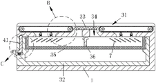
FIG. 1 is a schematic view of the overall structure provided by the present invention;
FIG. 2 is an enlarged view of the part A shown in FIG. 1;
FIG. 3 is a schematic view of the connection structure of the fixing block, the clamping plate and the ejector rod according to the present invention;
FIG. 4 is a schematic view of the connection structure of the driving plate, the mounting seat and the pressing block according to the present invention;
FIG. 5 is a schematic view of the internal structure of the base of the present invention;
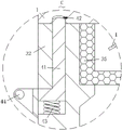
FIG. 6 is an enlarged view of the structure of the portion B shown in FIG. 5;
FIG. 7 is an enlarged view of the structure of the portion C shown in FIG. 5;
fig. 8 is a schematic view of a connection structure of the base and the rack according to the present invention.
In the figure: 1. a base, 2, an extrusion mechanism, 21, a support rod, 22, a top plate, 23, a hydraulic cylinder, 24, a guide rod, 25, a fixing sleeve, 26, a drive plate, 27, a mounting seat, 28, a compression spring, 29, a pressing block, 3, a collection mechanism, 31, a placement groove, 32, a collection box, 33, a placement net, 34, a through groove, 35, a filter net, 36, a pull rod, 4, a locking mechanism, 41, a clamping pin, 42, a clamping groove, 43, an abutting spring, 44, a handle, 5, a clamping mechanism, 51, a fixed block, 52, a clamping plate, 53, a pressure rod, 54, a push rod, 55, a buffer spring, 56, a drive rod, 57, a movable groove, 58, a movable rod, 59, a return spring, 6, a conveying mechanism, 61, a rack, 62, a conveyor belt, 63, a rotating shaft, 64, a belt pulley, 65, a conveyor belt, 66, a one-way bearing, 67, a roller, 68, a gear wheel disc, 7, a cleaning mechanism, 71, a guide plate, 72. guide slot, 73, fixing base, 74, connecting block, 75, expanding spring, 76, brush.
Detailed Description
In order to make the technical means, the creation characteristics, the achievement purposes and the effects of the invention easy to understand, the invention is further described with the specific embodiments.
As shown in fig. 1-8, the automobile filter element engine oil recovery device provided by the invention comprises a base 1, wherein an extrusion mechanism 2 is installed on the base 1, a collection mechanism 3 is installed inside the base 1, a locking mechanism 4 is connected to the collection mechanism 3, a clamping mechanism 5 is installed on the base 1, a conveying mechanism 6 is installed on the base 1, and a cleaning mechanism 7 is installed inside the base 1.
Specifically, the extruding mechanism 2 includes support rods 21, four support rods 21 are vertically and fixedly connected to the base 1, a top plate 22 is arranged on the base 1, the top plate 22 is fixedly connected to the four support rods 21, a hydraulic cylinder 23 is detachably connected to the top plate 22, the hydraulic cylinder 23 extends to the outside of the top plate 22, a drive plate 26 is connected to the hydraulic cylinder 23, a mounting seat 27 is mounted on the drive plate 26, a press block 29 is connected to the mounting seat 27, one end of the press block 29 is slidably connected to the inside of the mounting seat 27 through a plurality of compression springs 28, the top plate 22 is favorably mounted and supported under the action of the base 1 and the support rods 21, so that the hydraulic cylinder 23 is conveniently connected, the drive plate 26 and the press block 29 are driven to be pressed downwards through the driving work of the hydraulic cylinder 23, and the filter element placed on the base 1 is favorably extruded and deformed, the engine oil in the filter element is extruded and discharged, the pressing block 29 is favorable to have elasticity under the action of the plurality of compression springs 28, and the hydraulic cylinder 23 is prevented from being damaged.
Specifically, fixed cover 25 is installed at roof 22 both ends, two sliding connection has guide arm 24 on the fixed cover 25, two 24 one end of guide arm is connected with 26 both ends tops of drive plate respectively, through be favorable to under the effect of fixed cover 25 guide arm 24 can stretch out and draw back the slip, through be favorable to under the effect of guide arm 24 drive plate 26 has fine guide effect when sliding, and makes can not take place the skew during the slip of drive plate 26, and is convenient briquetting 29 is fine extrudees the filter core.
Specifically, collect mechanism 3 including collecting box 32, the inside sliding connection of base 1 has collection box 32, collect box 32 one end and extend to the base 1 outside, be equipped with standing groove 31 on the base 1, 1 central line department of base installs and places net 33, place net 33 and standing groove 31 intercommunication, 1 central line department of base is equipped with two and leads to groove 34, it is through leading to groove 34 and collection box 32 intercommunication to place net 33, through make things convenient for the filter core to carry out fine placing under standing groove 31's the effect, through under the effect of placing net 33, the machine oil that is favorable to extruding can pass through lead to groove 34 and get into collect the inside deposit of box 32, through taking out collection box 32 is convenient to retrieve the machine oil of depositing and draw.
It is specific, the inside block of collection box 32 is connected with filter screen 35, pull rod 36 is installed to filter screen 35 central line department, pull rod 36 is "T" shape structure, the length of pull rod 36 equals with the filter screen 35 degree of depth, through be favorable to filtering the machine oil of drippage under the effect of filter screen 35, make the inside debris of machine oil keep apart on the filter screen 35, make good machine oil get into collect box 32 inside and deposit, through after collection box 32 takes out, through the pulling pull rod 36, it is convenient right the clearance debris are taken out to filter screen 35.
Specifically, the locking mechanism 4 comprises a bayonet 41, the bayonet 41 is arranged in one end of the collecting box 32, the bayonet lock 41 is connected with the inner part of the collecting box 32 in a sliding way through an abutting spring 43, the bayonet lock 41 is in an L-shaped structure, a clamping groove 42 is arranged on the inner side of the base 1, one end of the clamping pin 41 is abutted against the inner part of the clamping groove 42, the other end of the bayonet 41 extends to the outer side of the collecting box 32, the other end of the bayonet 41 is provided with a handle 44, the handle 44 is connected with the outer side of the collecting box 32 in a sliding way through the bayonet 41, the bayonet 41 is in butt joint with the inside of the bayonet 42 under the action of the butt spring 43, so that the spacing between the collecting box 32 and the base 1 is limited and can not slip off, by pressing the handle 44, the bayonet 41 is conveniently driven to be separated from the bayonet 42 without the action of the abutting spring 43, so that the collection box 32 is conveniently pulled to be drawn out and cleaned by pulling the handle 44.
Specifically, fixture 5 includes fixed block 51, install two symmetric distribution's fixed block 51 on the base 1, two the fixed block 51 opposite side is connected with splint 52, splint 52 is the arc structure, two fixed block 51 internally mounted has movable rod 58, movable rod 58 passes through reset spring 59 and the inside sliding connection of fixed block 51, two movable rod 58 extends to the fixed block 51 outside and is connected with splint 52, two fixed block 51 is inside to be equipped with movable groove 57 respectively, the inside actuating lever 56 that is equipped with of movable groove 57, actuating lever 56 one end is rotated with splint 52 and is connected, sliding connection has ejector pin 54 on the fixed block 51, the actuating lever 56 other end rotates with ejector pin 54 and is connected, install depression bar 53 on the ejector pin 54, ejector pin 54 passes through buffer spring 55 and the inboard sliding connection of depression bar 53, places through the filter core place after placing on the net 33, by the downward sliding of the driving plate 26, the driving plate 26 presses the two pressing rods 53, the push rod 54 is driven to press the driving rod 56 in the movable groove 57 by the action of the buffer spring 55, the driving rod 56 drives the clamp plate 52 and the movable rod 58 to slide free from the action of the return spring 59, thereby clamping the filter element of the clamping plate 52, and simultaneously, the compression rod 53 and the ejector rod 54 have elasticity under the action of the buffer spring 55, thereby facilitating the driving plate 26 to slide downwards continuously, facilitating the pressing block 29 on the driving plate 26 to extrude the filter element to discharge the engine oil, after the driving plate 26 is lifted, the clamping plate 52 and the movable rod 58 are reset under the action of the reset spring 59, and drives the driving rod 56 and the ejector rod 54 to reset, so that the filter element can be conveniently clamped subsequently.
Specifically, the conveying mechanism 6 comprises rollers 67, two sets of rollers 67 are installed at two ends inside the base 1, the two sets of rollers 67 are rotatably connected with the inside of the base 1 through rotating shafts 63, two conveyor belts 62 are installed on the base 1, two ends of the conveyor belts 62 are connected with the rollers 67, the conveyor belts 62 are rotatably connected with the base 1 through the rollers 67, the conveyor belts 62 are communicated with the placing groove 31, two opposite rotating shafts 63 extend to the outside of the base 1, two belt discs 64 are installed on the rotating shafts 63, the two belt discs 64 are connected through a transmission belt 65, one rotating shaft 63 is provided with a one-way bearing 66, a gear disc 68 is installed on the one-way bearing 66, the gear disc 68 is rotatably connected with the inside of the base 1, a rack 61 is vertically and fixedly connected to the drive plate 26, and the rack 61 extends to the inside of the base 1, the rack 61 is slidably connected with the inside of the base 1, the rack 61 is engaged with the gear disc 68, when a plurality of filter cartridges are placed on the placement groove 31, the filter cartridges are placed on top of the two conveyor belts 62, the rack 61 is driven to slide in the inside of the base 1 by the ascending of the drive plate 26, the rack 61 drives the gear disc 68 and the one-way bearing 66 to drive the rotating shaft 63, and simultaneously the other rotating shaft 63 is rotated under the action of the drive belt 65 and the belt disc 64, so that the two conveyor belts 62 on the base 1 are synchronously rotated, the filter cartridges on the conveyor belts 62 are conveyed for a certain distance, the extruded filter cartridges are conveniently pushed, the non-extruded filter cartridges are conveyed between the two clamping plates 52, and when the baffle plate 26 is pressed down, the rack 61 slides down, under the action of the one-way bearing 66, the fluted disc cannot drive the rotating shaft 63 and the rolling shaft 67, so that the conveying belt 62 cannot rotate, and a conveyed filter element is conveniently clamped and extruded to discharge engine oil.
Specifically, the cleaning mechanism 7 includes a guide groove 72, two guide grooves 72 are respectively arranged at two ends inside the base 1, the conveyor belt 62 is communicated with the collecting box 32 through the guide grooves 72, two fixing seats 73 are arranged inside the guide grooves 72, two ends of each fixing seat 73 are fixedly connected with the inside of the base 1, two connecting blocks 74 are arranged on the base 1, each connecting block 74 is slidably connected with the inside of each fixing seat 73 through an expansion spring 75, a brush 76 is arranged on each connecting block 74, each brush 76 is abutted to the conveyor belt 62, a plurality of symmetrically-distributed guide plates 71 are arranged inside the collecting box 32, an included angle between each guide plate 71 and the corresponding collecting box 32 is 45 degrees, the brush 76 is conveniently mounted under the action of the corresponding fixing seat 73, the brush 76 is abutted to the conveyor belt 62 tightly under the action of the expansion springs 75, and the conveyor belt 62 synchronously rotates, the brush 76 is beneficial to scraping off the scraps attached to the conveyor belt 62, the scraps fall onto the filter screen 35 on the collecting box 32 through the guide groove 72 and are stored, and the guide of the scraps is facilitated under the action of the guide grooves, so that the scraps are uniformly scattered on the filter screen 35, and the subsequent cleaning is facilitated.
When the invention is used, firstly, the top plate 22 is favorably installed and supported under the action of the base 1 and the support rod 21, so that the hydraulic cylinder 23 is conveniently connected, the drive plate 26 and the press block 29 are driven to press downwards through the driving work of the hydraulic cylinder 23, the filter core placed on the base 1 is favorably extruded and deformed, the engine oil in the filter core is extruded and discharged, the press block 29 is favorably provided with elasticity under the action of a plurality of compression springs 28, the damage of the hydraulic cylinder 23 is prevented, the guide rod 24 can be favorably stretched and slid under the action of the fixed sleeve 25, the drive plate 26 has good guiding function when sliding under the action of the guide rod 24, the drive plate 26 cannot deviate when sliding, the press block 29 is favorably extruded to the filter core, the filter core is favorably placed under the action of the placing groove 31, and under the action of the placing net 33, the machine oil which is beneficial to extrusion can enter the collecting box 32 through the through groove 34 to be stored, the collected box 32 is taken out to facilitate the recovery and extraction of the stored machine oil, the machine oil which is dripped is beneficial to be filtered under the action of the filter screen 35, the sundries in the machine oil are isolated on the filter screen 35, the machine oil which is good enters the collecting box 32 to be stored, after the machine oil is taken out through the collecting box 32, the filter screen 35 is convenient to take out and clean the sundries by pulling the pull rod 36, the bayonet lock 41 is in butt joint with the inside of the clamping groove 42 under the action of the butt spring 43, the position between the collecting box 32 and the base 1 is limited and can not slip, the bayonet lock 41 is conveniently driven to break away from the action of the butt spring 43 and separate from the clamping groove 42 by pressing the handle 44, so that the collecting box 32 can be conveniently pulled out and cleaned, the gliding filter core is placed on the placing net 33 and passes through the driving plate 26, the driving plate 26 is enabled to extrude the two pressure rods 53, the push rod 54 is driven to extrude the driving rod 56 in the movable groove 57 under the action of the buffer spring 55, the driving rod 56 drives the clamping plate 52 and the movable rod 58 to slide under the action of the reset spring 59, so that the clamping plate 52 is clamped, meanwhile, the pressure rod 53 and the push rod 54 are enabled to have elasticity under the action of the buffer spring 55, so that the driving plate 26 can slide continuously, the pressing block 29 on the driving plate 26 can extrude and discharge engine oil to the filter element, after the driving plate 26 ascends, the clamping plate 52 and the movable rod 58 can reset under the action of the reset spring 59, and the driving rod 56 and the push rod 54 can reset, so that the filter element can be clamped subsequently, when a plurality of filter elements are placed on the placing groove 31, the filter element is placed on the tops of the two conveyor belts 62, and the rack 61 is driven to slide in the base 1 by the ascending of the driving plate 26, the rack 61 drives the gear disc 68 and the one-way bearing 66 to drive the rotating shaft 63, and simultaneously the other rotating shaft 63 is rotated under the action of the transmission belt 65 and the belt disc 64, so that the two transmission belts 62 on the base 1 can be synchronously rotated, a certain distance can be conveyed to filter elements on the transmission belts 62, the filter elements after being extruded can be conveniently pushed, the filter elements which are not extruded can be conveyed between the two clamping plates 52, when the baffle driving plate 26 is pressed downwards, the rack 61 slides downwards, the fluted disc can not drive the rotating shaft 63 and the rolling shaft 67 under the action of the one-way bearing 66, so that the transmission belts 62 can not rotate, the conveyed filter elements can be conveniently clamped and extruded to discharge engine oil, the brush 76 can be conveniently installed under the action of the fixing seat 73, the brush 76 can be tightly abutted against the transmission belts 62 under the action of the expansion spring 75, and the synchronous rotation of the transmission belts 62 can be favorable for scraping off debris adhered to the transmission belts 62 by the brush 76, and filter screen 35 that drops to on collecting box 32 through guide slot 72 deposits, is favorable to under the effect through a plurality of guiding gutters to the debris water conservancy diversion, makes things convenient for the even scattering of debris on filter screen 35, makes things convenient for follow-up clearance.
It will be evident to those skilled in the art that the invention is not limited to the details of the foregoing illustrative embodiments, and that the present invention may be embodied in other specific forms without departing from the spirit or essential attributes thereof. The present embodiments are therefore to be considered in all respects as illustrative and not restrictive, the scope of the invention being indicated by the appended claims rather than by the foregoing description, and all changes which come within the meaning and range of equivalency of the claims are therefore intended to be embraced therein. Any reference sign in a claim should not be construed as limiting the claim concerned.
Furthermore, it should be understood that although the present description refers to embodiments, not every embodiment may contain only a single embodiment, and such description is for clarity only, and those skilled in the art should integrate the description, and the embodiments may be combined as appropriate to form other embodiments understood by those skilled in the art.
Claims (9)
1. The utility model provides an automobile filter element machine oil recovery unit, its characterized in that, includes base (1), install extrusion mechanism (2) on base (1), base (1) internally mounted has collection mechanism (3), be connected with blocked mechanical system (4) on collecting mechanism (3), install fixture (5) on base (1), install conveying mechanism (6) on base (1), base (1) internally mounted has clearance mechanism (7).
2. The automobile filter element engine oil recovery device according to claim 1, characterized in that: extrusion mechanism (2) include bracing piece (21), four bracing pieces of perpendicular fixedly connected with (21) are gone up in base (1), be equipped with roof (22) on base (1), roof (22) and four bracing piece (21) fixed connection, can dismantle on roof (22) and be connected with pneumatic cylinder (23), pneumatic cylinder (23) extend to the roof (22) outside, be connected with drive plate (26) on pneumatic cylinder (23), install mount pad (27) on drive plate (26), be connected with briquetting (29) on mount pad (27), briquetting (29) one end is through a plurality of compression spring (28) and mount pad (27) inside sliding connection.
3. The automobile filter element engine oil recovery device according to claim 2, characterized in that: fixed cover (25) are installed at roof (22) both ends, two sliding connection has guide arm (24) on fixed cover (25), two guide arm (24) one end is connected with drive plate (26) both ends top respectively.
4. The automobile filter element engine oil recovery device according to claim 1, characterized in that: collect mechanism (3) including collecting box (32), base (1) inside sliding connection has collection box (32), collect box (32) one end and extend to base (1) outside, be equipped with standing groove (31) on base (1), base (1) central line department installs and places net (33), place net (33) and standing groove (31) intercommunication, base (1) central line department is equipped with two and leads to groove (34), it communicates with collection box (32) through leading to groove (34) to place net (33).
5. The automobile filter element engine oil recovery device according to claim 4, characterized in that: collect box (32) inside block and be connected with filter screen (35), pull rod (36) are installed to filter screen (35) central line department, pull rod (36) are "T" shape structure, the length of pull rod (36) equals with filter screen (35) degree of depth.
6. The automobile filter element engine oil recovery device according to claim 5, characterized in that: blocked mechanical system (4) include bayonet lock (41), collect box (32) one end internally mounted have bayonet lock (41), bayonet lock (41) through contradicting spring (43) and the inside sliding connection of collecting box (32), bayonet lock (41) are "L" shape structure, base (1) inboard is equipped with draw-in groove (42), bayonet lock (41) one end and the inside conflict of draw-in groove (42), bayonet lock (41) other end extends to the collection box (32) outside, handle (44) are installed to bayonet lock (41) other end, handle (44) pass through bayonet lock (41) and the collection box (32) outside sliding connection.
7. The automobile filter element engine oil recovery device according to claim 1, characterized in that: fixture (5) includes fixed block (51), install two symmetric distribution's fixed block (51) on base (1), two fixed block (51) opposite side is connected with splint (52), splint (52) are the arc structure, two fixed block (51) internally mounted has movable rod (58), movable rod (58) pass through reset spring (59) and fixed block (51) inside sliding connection, two movable rod (58) extend to fixed block (51) outside and are connected with splint (52), two fixed block (51) inside is equipped with movable groove (57) respectively, the inside actuating lever (56) that is equipped with of movable groove (57), actuating lever (56) one end is rotated with splint (52) and is connected, sliding connection has ejector pin (54) on fixed block (51), the actuating lever (56) other end rotates with ejector pin (54) and is connected, the push rod (54) is provided with a press rod (53), and the push rod (54) is connected with the inner side of the press rod (53) in a sliding mode through a buffer spring (55).
8. The automobile filter element engine oil recovery device according to claim 2, characterized in that: conveying mechanism (6) includes roller bearing (67), two sets of roller bearing (67) are installed at the inside both ends of base (1), and are two sets of roller bearing (67) are connected with base (1) internal rotation through pivot (63), install two conveyer belt (62) on base (1), conveyer belt (62) both ends are connected with roller bearing (67), conveyer belt (62) are connected with base (1) rotation through roller bearing (67), conveyer belt (62) and standing groove (31) intercommunication, wherein two are relative pivot (63) extend to the base (1) outside, two install pulley disc (64) on pivot (63), two pulley disc (64) are connected through drive belt (65), one of them install one-way bearing (66) on pivot (63), install gear disc (68) on one-way bearing (66), the gear plate (68) is rotatably connected with the inside of the base (1), a rack (61) is fixedly connected to the driving plate (26) in a vertical mode, the rack (61) extends to the inside of the base (1), the rack (61) is connected with the inside of the base (1) in a sliding mode, and the rack (61) is meshed with the gear plate (68).
9. The automobile filter element engine oil recovery device of claim 8, characterized in that: clearance mechanism (7) are including guide slot (72), base (1) inside both ends are equipped with guide slot (72) respectively, conveyer belt (62) are through guide slot (72) and collection box (32) intercommunication, two inside fixing base (73) of being equipped with of guide slot (72), fixing base (73) both ends and base (1) inside fixed connection, two install connecting block (74) on base (1), connecting block (74) are through expanding spring (75) and fixing base (73) inside sliding connection, install brush (76) on connecting block (74), brush (76) are contradicted with conveyer belt (62), collection box (32) internally mounted has guide plate (71) of a plurality of symmetric distributions, guide plate (71) and collection box (32) between the contained angle be 45 degrees.
Priority Applications (1)
| Application Number | Priority Date | Filing Date | Title |
|---|---|---|---|
| CN202210083701.0A CN114407410A (en) | 2022-01-25 | 2022-01-25 | Automobile filter element engine oil recovery device |
Applications Claiming Priority (1)
| Application Number | Priority Date | Filing Date | Title |
|---|---|---|---|
| CN202210083701.0A CN114407410A (en) | 2022-01-25 | 2022-01-25 | Automobile filter element engine oil recovery device |
Publications (1)
| Publication Number | Publication Date |
|---|---|
| CN114407410A true CN114407410A (en) | 2022-04-29 |
Family
ID=81277374
Family Applications (1)
| Application Number | Title | Priority Date | Filing Date |
|---|---|---|---|
| CN202210083701.0A Withdrawn CN114407410A (en) | 2022-01-25 | 2022-01-25 | Automobile filter element engine oil recovery device |
Country Status (1)
| Country | Link |
|---|---|
| CN (1) | CN114407410A (en) |
Cited By (1)
| Publication number | Priority date | Publication date | Assignee | Title |
|---|---|---|---|---|
| CN115644752A (en) * | 2022-10-31 | 2023-01-31 | 江苏洁路宝环保科技有限公司 | Intelligent electric floor sweeping machine filter element cleaning structure |
-
2022
- 2022-01-25 CN CN202210083701.0A patent/CN114407410A/en not_active Withdrawn
Cited By (1)
| Publication number | Priority date | Publication date | Assignee | Title |
|---|---|---|---|---|
| CN115644752A (en) * | 2022-10-31 | 2023-01-31 | 江苏洁路宝环保科技有限公司 | Intelligent electric floor sweeping machine filter element cleaning structure |
Similar Documents
| Publication | Publication Date | Title |
|---|---|---|
| CN113636267B (en) | Automatic insert machine charging equipment of diffusion with anti-fragmentation device | |
| CN112400938A (en) | Surface printing device for moon cake processing | |
| CN111251648A (en) | Sugarcane juicing equipment capable of automatically classifying residues | |
| CN114407410A (en) | Automobile filter element engine oil recovery device | |
| CN111515150B (en) | Automatic wiping arrangement of license plate | |
| CN111070395B (en) | Composite sheet processing is with equipment of napping | |
| CN210972522U (en) | Conveying device for classified treatment of garbage | |
| CN112429623A (en) | Escalator dust cleaning device and using method thereof | |
| CN216425674U (en) | Machine part conveyor | |
| CN114146912A (en) | Garrulous soap is retrieved and is used screening plant | |
| CN212193266U (en) | Rubber sheet slitter | |
| CN218588150U (en) | Lotus seed coring processing platform convenient to use | |
| CN219877379U (en) | Wild jujube pit removing and extracting device | |
| CN217550864U (en) | Washing machine backplate sheet metal component stamping die of convenient ejection of compact | |
| CN220176212U (en) | Gear grinding machine filter equipment | |
| CN218775483U (en) | Can collect stamping die of blanking clout | |
| CN219837027U (en) | Stamping die for automobile parts | |
| CN214781123U (en) | Wastewater treatment device for high-speed aluminum wire drawing oil production | |
| CN215696712U (en) | Carpet is with removing dust recovery processing device | |
| CN214605358U (en) | Waste plastic recycling bin structure | |
| CN216267777U (en) | Easy open can flattening recovery unit | |
| CN217831504U (en) | Bending device is used in processing of hexagonal spanner | |
| CN214395564U (en) | Tea juice draws uses extrusion device | |
| CN220846413U (en) | Spinning frame | |
| CN219947046U (en) | Metal impurity separating device in injection molding machine barrel |
Legal Events
| Date | Code | Title | Description |
|---|---|---|---|
| PB01 | Publication | ||
| PB01 | Publication | ||
| SE01 | Entry into force of request for substantive examination | ||
| SE01 | Entry into force of request for substantive examination | ||
| WW01 | Invention patent application withdrawn after publication |
Application publication date: 20220429 |
|
| WW01 | Invention patent application withdrawn after publication |