CN114406078A - Motor shaft outer lane forming device - Google Patents
Motor shaft outer lane forming device Download PDFInfo
- Publication number
- CN114406078A CN114406078A CN202111587414.5A CN202111587414A CN114406078A CN 114406078 A CN114406078 A CN 114406078A CN 202111587414 A CN202111587414 A CN 202111587414A CN 114406078 A CN114406078 A CN 114406078A
- Authority
- CN
- China
- Prior art keywords
- top surface
- mounting
- motor shaft
- forming device
- fixed mounting
- Prior art date
- Legal status (The legal status is an assumption and is not a legal conclusion. Google has not performed a legal analysis and makes no representation as to the accuracy of the status listed.)
- Pending
Links
- 238000005242 forging Methods 0.000 claims abstract description 26
- 238000003860 storage Methods 0.000 claims description 23
- 230000000694 effects Effects 0.000 claims 1
- 238000000034 method Methods 0.000 abstract description 18
- 230000008569 process Effects 0.000 abstract description 15
- 238000004519 manufacturing process Methods 0.000 abstract description 11
- 239000000463 material Substances 0.000 abstract description 11
- 238000012545 processing Methods 0.000 abstract description 11
- 238000003754 machining Methods 0.000 abstract description 6
- 238000007514 turning Methods 0.000 abstract description 4
- 238000001125 extrusion Methods 0.000 abstract 3
- 238000009987 spinning Methods 0.000 description 50
- 238000005498 polishing Methods 0.000 description 6
- 238000005516 engineering process Methods 0.000 description 5
- 230000007547 defect Effects 0.000 description 4
- 230000008859 change Effects 0.000 description 3
- 238000005520 cutting process Methods 0.000 description 3
- 230000009471 action Effects 0.000 description 2
- 230000009467 reduction Effects 0.000 description 2
- 239000011435 rock Substances 0.000 description 2
- 239000002699 waste material Substances 0.000 description 2
- 241001133184 Colletotrichum agaves Species 0.000 description 1
- 230000004075 alteration Effects 0.000 description 1
- 230000009286 beneficial effect Effects 0.000 description 1
- 238000005266 casting Methods 0.000 description 1
- 238000010276 construction Methods 0.000 description 1
- 238000010586 diagram Methods 0.000 description 1
- 238000009434 installation Methods 0.000 description 1
- 238000012986 modification Methods 0.000 description 1
- 230000004048 modification Effects 0.000 description 1
- 238000012958 reprocessing Methods 0.000 description 1
- 239000004576 sand Substances 0.000 description 1
- 238000006467 substitution reaction Methods 0.000 description 1
Images


Classifications
-
- B—PERFORMING OPERATIONS; TRANSPORTING
- B21—MECHANICAL METAL-WORKING WITHOUT ESSENTIALLY REMOVING MATERIAL; PUNCHING METAL
- B21D—WORKING OR PROCESSING OF SHEET METAL OR METAL TUBES, RODS OR PROFILES WITHOUT ESSENTIALLY REMOVING MATERIAL; PUNCHING METAL
- B21D22/00—Shaping without cutting, by stamping, spinning, or deep-drawing
- B21D22/14—Spinning
-
- B—PERFORMING OPERATIONS; TRANSPORTING
- B21—MECHANICAL METAL-WORKING WITHOUT ESSENTIALLY REMOVING MATERIAL; PUNCHING METAL
- B21D—WORKING OR PROCESSING OF SHEET METAL OR METAL TUBES, RODS OR PROFILES WITHOUT ESSENTIALLY REMOVING MATERIAL; PUNCHING METAL
- B21D37/00—Tools as parts of machines covered by this subclass
- B21D37/04—Movable or exchangeable mountings for tools
-
- B—PERFORMING OPERATIONS; TRANSPORTING
- B21—MECHANICAL METAL-WORKING WITHOUT ESSENTIALLY REMOVING MATERIAL; PUNCHING METAL
- B21D—WORKING OR PROCESSING OF SHEET METAL OR METAL TUBES, RODS OR PROFILES WITHOUT ESSENTIALLY REMOVING MATERIAL; PUNCHING METAL
- B21D37/00—Tools as parts of machines covered by this subclass
- B21D37/14—Particular arrangements for handling and holding in place complete dies
-
- B—PERFORMING OPERATIONS; TRANSPORTING
- B21—MECHANICAL METAL-WORKING WITHOUT ESSENTIALLY REMOVING MATERIAL; PUNCHING METAL
- B21D—WORKING OR PROCESSING OF SHEET METAL OR METAL TUBES, RODS OR PROFILES WITHOUT ESSENTIALLY REMOVING MATERIAL; PUNCHING METAL
- B21D53/00—Making other particular articles
- B21D53/10—Making other particular articles parts of bearings; sleeves; valve seats or the like
-
- H—ELECTRICITY
- H02—GENERATION; CONVERSION OR DISTRIBUTION OF ELECTRIC POWER
- H02K—DYNAMO-ELECTRIC MACHINES
- H02K15/00—Methods or apparatus specially adapted for manufacturing, assembling, maintaining or repairing of dynamo-electric machines
-
- H—ELECTRICITY
- H02—GENERATION; CONVERSION OR DISTRIBUTION OF ELECTRIC POWER
- H02K—DYNAMO-ELECTRIC MACHINES
- H02K15/00—Methods or apparatus specially adapted for manufacturing, assembling, maintaining or repairing of dynamo-electric machines
- H02K15/14—Casings; Enclosures; Supports
Abstract
The invention discloses a motor shaft outer ring forming device, which has the technical scheme that: comprises a workbench, four supporting blocks are fixedly arranged on the top surface of the workbench, a supporting rod is fixedly arranged on the top surface of each supporting block, a mounting plate is fixedly arranged on the top surface of each supporting rod, a through hole is formed in the top surface of each mounting plate, a hydraulic cylinder is fixedly arranged on the top surface of each mounting plate, a telescopic shaft of each hydraulic cylinder penetrates through the through hole and extends to the outside of the mounting plate, a forging component is arranged on the top surface of the workbench, the rotary extrusion machine is used for forging the outer ring of the motor shaft, and is characterized in that the first rotary wheel is arranged, the original blank is subjected to preliminary rotary extrusion processing through the first rotary wheel, the finished blank is finished through the first rotary wheel and the second rotary wheel, the produced outer ring of the motor shaft effectively reduces subsequent turning allowance, the manufacturing cost of the product is greatly reduced, the strength of the product after the rotary extrusion process is improved by 1 time relative to the material, and the machining quality of the product is improved.
Description
Technical Field
The invention relates to the technical field of forging of outer rings of motor shafts, in particular to a forming device for outer rings of motor shafts.
Background
The existing forming process of the outer ring of the motor shaft has the defects of large material waste and high cutting cost by using the traditional method of machining and turning chips, and adopts a forging process because the upper wall and the lower wall of a product are thick and thin and are hollow. The forging needs to increase the wall thickness allowance to meet the requirement, the whole process has the defects of increased forging materials, high cost of subsequent machining scraps, low strength of a cast product due to the defects of the process, easy generation of sand holes and shrinkage porosity and less adoption of a casting process for general automobile parts.
For example, publication numbers are: CN 213795619U's chinese patent wherein provides one, the processing of self-aligning roller bearing is with outer lane equipment of polishing, relates to the bearing processing field. This equipment of polishing of outer lane is used in processing of aligning roller bearing, the on-line screen storage device comprises a base, the last fixed surface of base is connected with the support frame, the right side fixedly connected with crossbeam of support frame, the right-hand member fixedly connected with motor of crossbeam, the output fixedly connected with axis of rotation of motor, movable groove has been seted up to the upper surface of base, movable groove's inside swing joint has the movable block. This equipment of polishing of outer lane is used in aligning roller bearing processing, pass through the tray, the fluting, the gag lever post, the loose ring, the vaulting pole, first spring and the mutually supporting of vaulting ring, it is convenient for fix the bearing inner race to reach, also be convenient for fix the bearing inner race of different internal diameters simultaneously, it is more convenient to make the during operation of polishing, it is very difficult when fixing to the bearing inner race to have solved present aligning roller bearing processing with outer lane equipment of polishing, lead to influencing the problem of the work efficiency of polishing, but nevertheless because lower wall thickness on the product, and hollow, it needs to increase the wall thickness surplus and satisfy to forge, whole technology forges the material increase, processingquality is difficult to guarantee.
Disclosure of Invention
Aiming at the defects of the prior art, the invention provides a motor shaft outer ring forming device, which solves the problem that the processing quality of the traditional forging process cannot be ensured.
The technical purpose of the invention is realized by the following technical scheme:
a motor shaft outer ring forming device comprises: the utility model discloses a motor shaft forging device, including workstation, the top surface fixed mounting of workstation has four supporting shoes, the top surface fixed mounting of supporting shoe has the bracing piece, the top surface fixed mounting of bracing piece has the mounting panel, the top surface of mounting panel has been seted up and has been run through the mouth, the top surface fixed mounting of mounting panel has hydraulic cylinder, hydraulic cylinder's telescopic shaft passes and runs through the mouth and extend to the outside of mounting panel, the top surface of workstation is provided with forges the subassembly for forge the motor shaft outer lane.
Through adopting above-mentioned technical scheme, through setting up the forging subassembly, when current forging technique carries out forging process to the motor shaft outer lane again, can cause the extravagant big while of material through processing turning, the cutting cost is high, through artifical forging process, because the upper and lower wall of product is thinner, and inside hollow structure forges the thickness that needs increase the wall, the material that can the greatly increased material, through the forging subassembly that sets up, utilize spinning process to improve the intensity of product, reduce the cost of production.
Preferably, the forging assembly comprises: an upper die, wherein the upper die is movably arranged at one end of a hydraulic cylinder, a chassis is fixedly arranged on the top surface of a workbench, a mounting disc is fixedly arranged on the top surface of the chassis, a lower die is movably arranged on the top surface of the mounting disc, a cavity is formed in the lower die, a die core is fixedly arranged in the cavity, two clamping plates are fixedly arranged on the top surface of the die core, an original blank is movably clamped between the two clamping plates, two sliding tables are fixedly arranged on the top surface of the workbench, a mounting hole is formed in one side of each sliding table, a servo motor is fixedly arranged in the mounting hole, a lead screw is fixedly connected with a shaft of the servo motor, a rotating hole is formed in one side of each sliding table, the lead screw is sleeved with the rotating hole, a sliding block is connected with the outer thread of the lead screw, and a first rotating wheel is movably arranged on the top surface of the sliding block, the first rotary wheel.
Through adopting above-mentioned technical scheme, through setting up first spinning roller, the staff places the bed die back to original blank, starts hydraulic cylinder and drives the mould, makes mould and bed die closely centre gripping together, drives first spinning roller and carries out the spinning to original blank at start-up servo motor to obtain semi-manufactured goods blank, spinning through other spinning rollers produces finished product blank at last, effectual follow-up lathe work's of reduction surplus has improved production efficiency greatly.
Preferably, a storage tank is arranged on one side of the workbench, a storage box is movably arranged in the storage tank, a second rotary wheel is movably arranged in the storage box, and a handle is fixedly arranged on one side of the storage box.
Through adopting above-mentioned technical scheme, through setting up the storage box, make things convenient for the staff to save the second revolves the wheel, prevent that the second from being revolved the wheel and being dismantled the back by the staff and put in disorder at will, cause losing of second revolves the wheel easily.
Preferably, the top surface of the first rotary wheel is provided with a first connecting hole, the top surface of the sliding block is provided with a second connecting hole, the inner thread of the first connecting hole is connected with a connecting bolt, and the connecting bolt penetrates through the first connecting hole and is in threaded connection with the second connecting hole.
Through adopting above-mentioned technical scheme, through setting up connecting bolt, when processing and forging motor shaft outer lane, need use first spinning wheel and second spinning wheel to process, when first spinning wheel is changed to needs, the staff can dismantle the back to first spinning wheel through wrench movement connecting bolt, installs the second spinning wheel, has made things convenient for the staff to change the spinning wheel.
Preferably, the top surface of the chassis is provided with a rotating groove, the bottom surface inside the rotating groove is fixedly provided with a motor, and a shaft of the motor is fixedly connected with the mounting disc.
Through adopting above-mentioned technical scheme, through setting up the motor, install first spinning wheel and second spinning wheel respectively on two slip tables as the staff, through the device of mounting disc, the different spinning wheels are handled every one end, if the mounting disc can not rotate, the staff can only install same kind of spinning wheel at both ends to in the course of working, need continuous dismantlement and the different spinning wheels of installation, rotate through setting up the electronic mounting disc of motor, improved the production efficiency of device.
Preferably, the top surface of the mounting disc is fixedly provided with a limiting ring, the inner circular wall surface of the limiting ring is fixedly provided with two springs, and two clamping blocks are arranged inside the limiting ring and fixedly connected with the springs.
Through adopting above-mentioned technical scheme, through setting up the grip block, after the spacing intra-annular was placed to the bed die, two grip blocks in the spacing intra-annular can carry out the clamping action through the elasticity of spring to the bottom of bed die, place when the device operation, the bed die appears rocking, causes the mould and the bed die can not perfectly agree with.
Preferably, the top surface of the upper die is provided with a clamping groove, and the clamping groove is movably clamped with a telescopic shaft of the hydraulic cylinder.
Through adopting above-mentioned technical scheme, through setting up the joint groove, after hydraulic cylinder and last mould joint together, make things convenient for the staff to take off when changing the mould.
Preferably, the two sides of the workbench are both provided with supporting grooves, the bottom surface inside the supporting grooves is provided with supporting holes, and supporting columns are fixedly installed inside the supporting holes.
Through adopting above-mentioned technical scheme, through setting up the support column, when the device is at the operation in-process, the device body needs remain stable, if produce and rock, cause first wheel and the second to revolve the wheel and appear the error when forging original blank, through the bottom surface block rubber of support column, improve the stability of device body, prevent that the device from appearing rocking easily.
In summary, the invention mainly has the following beneficial effects:
through setting up first spinning roller, after the mould was placed to original blank to the staff, start servo motor and drive first spinning roller and process original blank, original blank can be processed into semi-manufactured goods blank, the staff dismantles first spinning roller again, install the second spinning roller, process semi-manufactured goods blank again, reachs off-the-shelf blank at last, carry out the spinning process to original blank through first spinning roller and second spinning roller, the effectual subsequent lathe work surplus that has reduced of motor shaft outer lane of producing, great reduction the product manufacturing cost, the product strength after the spinning process is made has improved 1 times for material itself, product machining quality has been improved.
Through setting up the spacing ring, the staff places the die block in the spacing ring, and the grip block in the spacing ring can carry out the clamping action to the die block through the elasticity of spring, has prevented that the die block from appearing rocking in the course of working, causes the production quality to descend.
Through setting up connecting bolt, when carrying out the spinning technology to the motor shaft outer lane, need use different spinning rollers, the staff need frequent first spinning roller of change and second spinning roller in process of production, through connecting bolt, install first spinning roller and second spinning roller on the slider, the staff only needs wrench movement connecting bolt just can conveniently improve the efficiency of production to the change of spinning roller.
Drawings
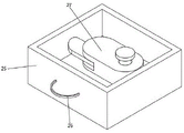
FIG. 1 is a schematic perspective view of the present invention;
FIG. 2 is a schematic view of the slider structure of the present invention;
FIG. 3 is a schematic diagram of a clamping plate structure of the present invention;
FIG. 4 is a schematic view of the storage case structure of the present invention;
FIG. 5 is a schematic view of the construction of the chassis of the present invention;
FIG. 6 is a schematic view of a split structure of the stop collar of the present invention;
fig. 7 is a schematic view of the structure of the snap groove of the present invention.
Reference numerals: 1. a work table; 2. a support block; 3. a support bar; 4. mounting a plate; 5. a through opening; 6. a hydraulic cylinder; 7. an upper die; 8. a chassis; 9. mounting a disc; 10. a lower die; 11. a cavity; 12. a mold core; 13. a clamping plate; 14. original blank; 15. a sliding table; 16. mounting holes; 17. a servo motor; 18. a screw rod; 19. a slider; 20. a first spinning wheel; 21. a first connection hole; 22. a second connection hole; 23. a connecting bolt; 24. a storage tank; 25. a storage box; 26. a handle; 27. a second spinning wheel; 28. a rotating groove; 29. a motor; 30. a limiting ring; 31. a spring; 32. a clamping block; 33. a clamping groove; 34. a support groove; 35. a support hole; 36. a support pillar; 37. the hole is rotated.
Detailed Description
The technical solutions in the embodiments of the present invention will be clearly and completely described below with reference to the drawings in the embodiments of the present invention, and it is obvious that the described embodiments are only a part of the embodiments of the present invention, and not all of the embodiments. All other embodiments, which can be derived by a person skilled in the art from the embodiments given herein without making any creative effort, shall fall within the protection scope of the present invention.
Referring to fig. 1, a forming device for an outer ring of a motor shaft includes: the working table 1 is of a rectangular structure, four supporting blocks 2 are fixedly mounted on the top surface of the working table 1, the supporting blocks 2 are of a cylindrical structure, supporting rods 3 are fixedly mounted on the top surface of the supporting blocks 2, the supporting rods 3 are of a cylindrical structure, a mounting plate 4 is fixedly mounted on the top surface of the supporting rods 3, the mounting plate 4 is of a rectangular structure, a through hole 5 is formed in the top surface of the mounting plate 4, the through hole 5 is a rectangular through hole, a hydraulic cylinder 6 is fixedly mounted on the top surface of the mounting plate 4, the hydraulic cylinder 6 is of an existing structure and is not described herein in detail, a telescopic shaft of the hydraulic cylinder 6 penetrates through the through hole 5 and extends to the outside of the mounting plate 4, a forging assembly is arranged on the top surface of the working table 1 and is used for forging the outer ring of a motor shaft, and by means of the forging assembly, when the forging process is carried out on the outer ring of the motor shaft by means of the existing forging technology, waste of materials is caused by machining vehicle scraps, cutting cost is high, through the manual forging technology, because the upper and lower wall of product is thinner, and inside hollow structure forges the thickness that needs to increase the wall moreover, and the material of material that can greatly increased utilizes spinning technology to improve the intensity of product, reduces the cost of production through the forging subassembly that sets up.
Referring to fig. 1, 2, 3 and 7, the forging assembly includes: an upper die 7, wherein the upper die 7 is movably arranged at one end of a hydraulic cylinder 6, the top surface of the upper die 7 is provided with a clamping groove 33, the clamping groove 33 is a circular groove, the clamping groove 33 is movably clamped with a telescopic shaft of the hydraulic cylinder 6, through the arrangement of the clamping groove 33, when the hydraulic cylinder 6 is clamped with the upper die 7, a worker can conveniently take down the upper die 7 when replacing the upper die 7, the top surface of a workbench 1 is fixedly provided with a chassis 8, the chassis 8 is in a round block structure, the top surface of the chassis 8 is fixedly provided with a mounting disc 9, the mounting disc 9 is in a round block structure, the top surface of the mounting disc 9 is movably provided with a lower die 10, the interior of the lower die 10 is provided with a cavity 11, the interior of the cavity 11 is fixedly provided with a die core 12, the top surface of the die core 12 is fixedly provided with two clamping plates 13, an original blank 14 is movably clamped between the two clamping plates 13, and the top surface of the workbench 1 is fixedly provided with two sliding tables 15, one side of the sliding table 15 is provided with a mounting hole 16, the mounting hole 16 is a circular through hole, a servo motor 17 is fixedly installed inside the mounting hole 16, the servo motor 17 is an existing structure and is not described herein, a shaft of the servo motor 17 is fixedly connected with a screw rod 18, one side of the sliding table 15 is provided with a rotating hole 37, the rotating hole 37 is a circular through hole, the screw rod 18 is rotatably sleeved with the rotating hole 37, the outer thread of the screw rod 18 is connected with a slide block 19, the slide block 19 is of a rectangular structure, a first rotating wheel 20 is movably installed on the top surface of the slide block 19, the first rotating wheel 20 is arranged, through the arrangement of the first rotating wheel 20, after a worker places an original blank 14 on the lower mold 10, the hydraulic cylinder 6 is started to drive the upper mold 7 to tightly clamp the upper mold 7 and the lower mold 10 together, and the servo motor 17 is started to drive the first rotating wheel 20 to spin the original blank 14, so as to obtain a semi-finished blank, the finished blank is finally produced by spinning through other spinning wheels, the allowance of subsequent turning is effectively reduced, and the production efficiency is greatly improved.
Referring to fig. 1, 2, 4 and 5, a storage groove 24 is formed at one side of a workbench 1, the storage groove 24 is a rectangular groove, a storage box 25 is movably installed inside the storage box 24, a second spinning wheel 27 is movably installed inside the storage box 25, a handle 26 is fixedly installed at one side of the storage box 25, by arranging the storage box 25, a worker can conveniently store the second spinning wheel 27, the second spinning wheel 27 is prevented from being randomly placed after being disassembled by the worker, the loss of the second spinning wheel 27 is easily caused, a first connection hole 21 is formed at the top surface of the first spinning wheel 20, the first connection hole 21 is a circular through hole, a second connection hole 22 is formed at the top surface of the sliding block 19, the second connection hole 22 is a circular through hole, a connection bolt 23 is connected to the inner thread of the first connection hole 21, the connection bolt 23 penetrates through the first connection hole 21 and is in threaded connection with the second connection hole 22, by arranging the connection bolt 23, when the outer ring of the motor shaft is machined and forged, a first rotating wheel 20 and a second rotating wheel 27 are needed to be machined, when the first rotating wheel 20 needs to be replaced, an operator can disassemble the first rotating wheel 20 by twisting the connecting bolt 23, then install the second rotating wheel 27, so that the operator can conveniently replace the rotating wheels, the top surface of the chassis 8 is provided with a rotating groove 28, the inner bottom surface of the rotating groove 28 is fixedly provided with a motor 29, the shaft of the motor 29 is fixedly connected with the mounting disc 9, by arranging the motor 29, when the operator respectively installs the first rotating wheel 20 and the second rotating wheel 27 on the two sliding tables 15, by means of the mounting disc 9, different rotating wheels are used for processing each end, if the mounting disc 9 cannot rotate, the operator can only install the same rotating wheel at two ends, so that in the machining process, different rotating wheels need to be continuously disassembled and installed, by arranging the motor 29 to rotate the electric mounting disc 9, the production efficiency of the device is improved.
Referring to fig. 1, 2, 4 and 6, a limiting ring 30 is fixedly installed on the top surface of the mounting plate 9, the limiting ring 30 is of a circular ring structure, two springs 31 are fixedly installed on the inner circular wall surface of the limiting ring 30, two clamping blocks 32 are arranged inside the limiting ring 30, the clamping blocks 32 are fixedly connected with the springs 31, by arranging the clamping blocks 32, after the lower mold 10 is placed in the limiting ring 30, the two clamping blocks 32 in the limiting ring 30 can clamp the bottom of the lower mold 10 through the elastic force of the springs 31, when the device is placed in operation, the lower mold 10 shakes to cause that the upper mold 7 and the lower mold 10 cannot be perfectly fitted, support grooves 34 are formed on both sides of the workbench 1, support holes 35 are formed in the inner bottom surfaces of the support grooves 34, support pillars 36 are fixedly installed inside the support holes 35, by arranging the support pillars 36, when the device is in operation, the device body needs to remain stable, if the device body rocks, causes first spinning wheel 20 and second spinning wheel 27 to appear the error when forging original blank 14, through the bottom surface block rubber of support column 36, improves the stability of device body, prevents that the device from appearing rocking easily.
The working principle is as follows: referring to fig. 1-6, a worker first places a lower mold 10 in a limiting ring 30 on a mounting plate 9 to clamp the lower mold 10, so as to prevent the lower mold 10 from shaking during the reprocessing process, then places an original blank 14 in the lower mold 10, starts a hydraulic cylinder 6 to drive an upper mold 7, so that the upper mold 7 and the lower mold 10 are combined together, installs a first spinning wheel 20 on a sliding block 19 through a connecting bolt 23, starts a servo motor 17 to drive the first spinning wheel 20 to spin the original blank 14, so as to process the blank into a semi-finished blank, then carries out normalizing treatment on the semi-finished blank, refines and homogenizes the components, then places the normalized semi-finished blank back into the mold, takes out a second spinning wheel 27 from a storage box 25, replaces one of the two first spinning wheels 20 with the second spinning wheel 27, and incorporates reasonable processing parameters, and (3) performing alternate spinning forming at staggered intervals up and down to obtain a finished blank with good quality.
Although embodiments of the present invention have been shown and described, it will be appreciated by those skilled in the art that changes, modifications, substitutions and alterations can be made in these embodiments without departing from the principles and spirit of the invention, the scope of which is defined in the appended claims and their equivalents.
Claims (8)
1. The utility model provides a motor shaft outer lane forming device which characterized in that includes: workstation (1), the top surface fixed mounting of workstation (1) has four supporting shoes (2), the top surface fixed mounting of supporting shoe (2) has bracing piece (3), the top surface fixed mounting of bracing piece (3) has mounting panel (4), run through mouth (5) have been seted up to the top surface of mounting panel (4), the top surface fixed mounting of mounting panel (4) has hydraulic cylinder (6), the telescopic shaft of hydraulic cylinder (6) passes and runs through mouth (5) and extend to the outside of mounting panel (4), the top surface of workstation (1) is provided with forges the subassembly for forge the motor shaft outer lane.
2. The apparatus of claim 1, wherein the forging assembly comprises: go up mould (7), go up mould (7) movable mounting in the one end of hydraulic cylinder (6), the top surface fixed mounting of workstation (1) has chassis (8), the top surface fixed mounting on chassis (8) has mounting disc (9), the top surface movable mounting of mounting disc (9) has bed die (10), cavity (11) have been seted up to the inside of bed die (10), the inside fixed mounting of cavity (11) has mold core (12), the top surface fixed mounting of mold core (12) has two grip blocks (13), two the activity joint has original blank (14) between grip block (13), workstation (1) top surface fixed mounting has two slip tables (15), mounting hole (16) have been seted up to one side of slip table (15), the inside fixed mounting of mounting hole (16) has servo motor (17), the axle fixedly connected with lead screw (18) of servo motor (17), rotation hole (37) have been seted up to one side of slip table (15), lead screw (18) rotate the cover with rotation hole (37) and establish, the outside threaded connection of lead screw (18) has slider (19), the top surface movable mounting of slider (19) has first gyro wheel (20), first gyro wheel (20).
3. The motor shaft outer ring forming device as claimed in claim 1, wherein a storage groove (24) is formed in one side of the workbench (1), a storage box (25) is movably mounted in the storage groove (24), a second rotating wheel (27) is movably mounted in the storage box (25), and a handle (26) is fixedly mounted on one side of the storage box (25).
4. The forming device of the outer ring of the motor shaft as claimed in claim 2, wherein a first connecting hole (21) is formed on a top surface of the first rotating wheel (20), a second connecting hole (22) is formed on a top surface of the sliding block (19), a connecting bolt (23) is connected to an inner thread of the first connecting hole (21), and the connecting bolt (23) penetrates through the first connecting hole (21) and is connected with the second connecting hole (22) in a threaded manner.
5. The forming device for the outer ring of the motor shaft as claimed in claim 2, wherein a rotating groove (28) is formed in the top surface of the chassis (8), a motor (29) is fixedly mounted on the inner bottom surface of the rotating groove (28), and a shaft of the motor (29) is fixedly connected with the mounting plate (9).
6. The motor shaft outer ring forming device as claimed in claim 2, wherein a limiting ring (30) is fixedly mounted on the top surface of the mounting disc (9), two springs (31) are fixedly mounted on the inner circular wall surface of the limiting ring (30), two clamping blocks (32) are arranged inside the limiting ring (30), and the clamping blocks (32) are fixedly connected with the springs (31).
7. The forming device for the outer ring of the motor shaft as claimed in claim 2, wherein a clamping groove (33) is formed in the top surface of the upper die (7), and the clamping groove (33) is movably clamped with the telescopic shaft of the hydraulic cylinder (6).
8. The forming device for the outer ring of the motor shaft as claimed in claim 1, wherein support grooves (34) are formed on both sides of the workbench (1), support holes (35) are formed in the bottom surfaces of the support grooves (34), and support columns (36) are fixedly mounted inside the support holes (35).
Priority Applications (1)
| Application Number | Priority Date | Filing Date | Title |
|---|---|---|---|
| CN202111587414.5A CN114406078A (en) | 2021-12-23 | 2021-12-23 | Motor shaft outer lane forming device |
Applications Claiming Priority (1)
| Application Number | Priority Date | Filing Date | Title |
|---|---|---|---|
| CN202111587414.5A CN114406078A (en) | 2021-12-23 | 2021-12-23 | Motor shaft outer lane forming device |
Publications (1)
| Publication Number | Publication Date |
|---|---|
| CN114406078A true CN114406078A (en) | 2022-04-29 |
Family
ID=81267254
Family Applications (1)
| Application Number | Title | Priority Date | Filing Date |
|---|---|---|---|
| CN202111587414.5A Pending CN114406078A (en) | 2021-12-23 | 2021-12-23 | Motor shaft outer lane forming device |
Country Status (1)
| Country | Link |
|---|---|
| CN (1) | CN114406078A (en) |
Cited By (1)
| Publication number | Priority date | Publication date | Assignee | Title |
|---|---|---|---|---|
| CN115430746A (en) * | 2022-11-09 | 2022-12-06 | 四川富士电机有限公司 | Windscreen wiper arm band iron forming device |
Citations (10)
| Publication number | Priority date | Publication date | Assignee | Title |
|---|---|---|---|---|
| CN102581104A (en) * | 2012-03-07 | 2012-07-18 | 黄石华力锻压机床有限公司 | Spinning machine for thickening disk periphery |
| CN104307954A (en) * | 2014-10-15 | 2015-01-28 | 西安交通大学 | Spinning machine capable of cutting burrs for large grooved pulley |
| US20190151923A1 (en) * | 2016-05-18 | 2019-05-23 | Thyssenkrupp Steel Europe Ag | Method for Producing a Formed Body |
| CN209565408U (en) * | 2019-01-30 | 2019-11-01 | 宁波永享铜管道有限公司 | A kind of spinning machine |
| CN209935632U (en) * | 2019-01-14 | 2020-01-14 | 重庆伊洛美克动力总成有限公司 | Structure for strongly spinning trapezoidal spline in thin-wall steel plate |
| CN212123000U (en) * | 2020-04-17 | 2020-12-11 | 广州好司机汽车电子有限公司 | Clamping device is used in car lamp production |
| CN212310536U (en) * | 2020-04-03 | 2021-01-08 | 浙江天洲车轮有限公司 | Hub forming device |
| CN212397960U (en) * | 2020-05-28 | 2021-01-26 | 杭州明锐五金科技有限公司 | Production equipment for mechanical forging and pressing |
| CN212397871U (en) * | 2020-04-15 | 2021-01-26 | 南京康筹工业技术有限公司 | Punching, spinning and forming integrated machine |
| US20210023602A1 (en) * | 2019-07-22 | 2021-01-28 | Xi'an Jiaotong University | Full-electric servo vertical three-counter-roller driving power spinning device |
-
2021
- 2021-12-23 CN CN202111587414.5A patent/CN114406078A/en active Pending
Patent Citations (10)
| Publication number | Priority date | Publication date | Assignee | Title |
|---|---|---|---|---|
| CN102581104A (en) * | 2012-03-07 | 2012-07-18 | 黄石华力锻压机床有限公司 | Spinning machine for thickening disk periphery |
| CN104307954A (en) * | 2014-10-15 | 2015-01-28 | 西安交通大学 | Spinning machine capable of cutting burrs for large grooved pulley |
| US20190151923A1 (en) * | 2016-05-18 | 2019-05-23 | Thyssenkrupp Steel Europe Ag | Method for Producing a Formed Body |
| CN209935632U (en) * | 2019-01-14 | 2020-01-14 | 重庆伊洛美克动力总成有限公司 | Structure for strongly spinning trapezoidal spline in thin-wall steel plate |
| CN209565408U (en) * | 2019-01-30 | 2019-11-01 | 宁波永享铜管道有限公司 | A kind of spinning machine |
| US20210023602A1 (en) * | 2019-07-22 | 2021-01-28 | Xi'an Jiaotong University | Full-electric servo vertical three-counter-roller driving power spinning device |
| CN212310536U (en) * | 2020-04-03 | 2021-01-08 | 浙江天洲车轮有限公司 | Hub forming device |
| CN212397871U (en) * | 2020-04-15 | 2021-01-26 | 南京康筹工业技术有限公司 | Punching, spinning and forming integrated machine |
| CN212123000U (en) * | 2020-04-17 | 2020-12-11 | 广州好司机汽车电子有限公司 | Clamping device is used in car lamp production |
| CN212397960U (en) * | 2020-05-28 | 2021-01-26 | 杭州明锐五金科技有限公司 | Production equipment for mechanical forging and pressing |
Cited By (1)
| Publication number | Priority date | Publication date | Assignee | Title |
|---|---|---|---|---|
| CN115430746A (en) * | 2022-11-09 | 2022-12-06 | 四川富士电机有限公司 | Windscreen wiper arm band iron forming device |
Similar Documents
| Publication | Publication Date | Title |
|---|---|---|
| CN106041225B (en) | A kind of tooth socket precise machining device of gear | |
| CN110280644B (en) | Automatic stamping device of hardware mould | |
| CN114406078A (en) | Motor shaft outer lane forming device | |
| CN207656348U (en) | A kind of reducer shell-drilling-and-tapping turnover jig | |
| CN211386924U (en) | Double-cutter vertical lathe device for machining spoke | |
| CN211386923U (en) | Single-tool vertical lathe device for machining spoke | |
| CN203031457U (en) | Combined clamp of grinding rocker | |
| CN206689671U (en) | A kind of adjustable jig | |
| CN213164087U (en) | Automobile part tapping and grinding die | |
| CN208840876U (en) | Drilling and milling machine is used in a kind of production of motor | |
| CN201108937Y (en) | Device for belt wheel spinning | |
| CN101823095A (en) | Gantry-type rotary pressing machine | |
| CN213730967U (en) | Brake shoe grinding device | |
| CN114454000A (en) | Knuckle, knuckle bearing hole machining equipment and knuckle machining process | |
| CN113172285A (en) | High-strength nut forming machine and forming method | |
| CN211839727U (en) | Hub spinning machine | |
| CN212216157U (en) | Material feeding and primary filtering machine for hydroxychloroquine sulfate raw material sulfuric acid | |
| CN113580420A (en) | Cutting device for waste tire processing | |
| CN106373771A (en) | Large-scale coil winding and rotating platform | |
| CN112605230A (en) | Trimming die for bolt | |
| CN202462053U (en) | Rotary butt-clamp mechanism and turning clamp device comprising same | |
| CN112916966A (en) | Rotary workbench for gear blank machining and use method thereof | |
| CN202667819U (en) | Material pressing device for automatic interior angle chamfering machine | |
| CN201676941U (en) | Gantry-type spinning machine | |
| CN217372083U (en) | Fixing device for production and processing of mechanical parts |
Legal Events
| Date | Code | Title | Description |
|---|---|---|---|
| PB01 | Publication | ||
| PB01 | Publication | ||
| SE01 | Entry into force of request for substantive examination | ||
| SE01 | Entry into force of request for substantive examination |