CN114371483A - Laser radar ranging method and device, laser radar and robot - Google Patents
Laser radar ranging method and device, laser radar and robot Download PDFInfo
- Publication number
- CN114371483A CN114371483A CN202210274320.0A CN202210274320A CN114371483A CN 114371483 A CN114371483 A CN 114371483A CN 202210274320 A CN202210274320 A CN 202210274320A CN 114371483 A CN114371483 A CN 114371483A
- Authority
- CN
- China
- Prior art keywords
- ranging
- light spot
- range
- spot
- result
- Prior art date
- Legal status (The legal status is an assumption and is not a legal conclusion. Google has not performed a legal analysis and makes no representation as to the accuracy of the status listed.)
- Granted
Links
- 238000000034 method Methods 0.000 title claims abstract description 64
- 238000004364 calculation method Methods 0.000 claims description 31
- 238000005259 measurement Methods 0.000 claims description 19
- 239000000126 substance Substances 0.000 claims description 9
- 238000004590 computer program Methods 0.000 claims description 8
- 238000004422 calculation algorithm Methods 0.000 description 16
- 238000010586 diagram Methods 0.000 description 13
- 238000003860 storage Methods 0.000 description 13
- 238000004891 communication Methods 0.000 description 10
- 238000004140 cleaning Methods 0.000 description 6
- 238000001914 filtration Methods 0.000 description 6
- 238000012545 processing Methods 0.000 description 6
- 230000008569 process Effects 0.000 description 5
- 239000000463 material Substances 0.000 description 4
- 238000010408 sweeping Methods 0.000 description 4
- 230000006870 function Effects 0.000 description 3
- 230000003287 optical effect Effects 0.000 description 3
- XEEYBQQBJWHFJM-UHFFFAOYSA-N Iron Chemical compound [Fe] XEEYBQQBJWHFJM-UHFFFAOYSA-N 0.000 description 2
- 230000009286 beneficial effect Effects 0.000 description 2
- 238000001514 detection method Methods 0.000 description 2
- 230000007613 environmental effect Effects 0.000 description 2
- 230000004807 localization Effects 0.000 description 2
- 230000033001 locomotion Effects 0.000 description 2
- 238000013507 mapping Methods 0.000 description 2
- 238000012986 modification Methods 0.000 description 2
- 230000004048 modification Effects 0.000 description 2
- 238000012544 monitoring process Methods 0.000 description 2
- 238000012546 transfer Methods 0.000 description 2
- 230000009466 transformation Effects 0.000 description 2
- 238000005406 washing Methods 0.000 description 2
- 229910052782 aluminium Inorganic materials 0.000 description 1
- XAGFODPZIPBFFR-UHFFFAOYSA-N aluminium Chemical compound [Al] XAGFODPZIPBFFR-UHFFFAOYSA-N 0.000 description 1
- 238000003491 array Methods 0.000 description 1
- 230000005540 biological transmission Effects 0.000 description 1
- 230000008859 change Effects 0.000 description 1
- 238000013500 data storage Methods 0.000 description 1
- 239000000428 dust Substances 0.000 description 1
- 238000010410 dusting Methods 0.000 description 1
- 230000000694 effects Effects 0.000 description 1
- 230000005611 electricity Effects 0.000 description 1
- 238000005516 engineering process Methods 0.000 description 1
- 210000001061 forehead Anatomy 0.000 description 1
- 229910052742 iron Inorganic materials 0.000 description 1
- 238000004519 manufacturing process Methods 0.000 description 1
- 229910052751 metal Inorganic materials 0.000 description 1
- 239000002184 metal Substances 0.000 description 1
- 238000010295 mobile communication Methods 0.000 description 1
- 230000004297 night vision Effects 0.000 description 1
- 230000000474 nursing effect Effects 0.000 description 1
- 238000005457 optimization Methods 0.000 description 1
- 239000002245 particle Substances 0.000 description 1
- 238000006467 substitution reaction Methods 0.000 description 1
- 230000001360 synchronised effect Effects 0.000 description 1
- XLYOFNOQVPJJNP-UHFFFAOYSA-N water Substances O XLYOFNOQVPJJNP-UHFFFAOYSA-N 0.000 description 1
Images


Classifications
-
- G—PHYSICS
- G01—MEASURING; TESTING
- G01S—RADIO DIRECTION-FINDING; RADIO NAVIGATION; DETERMINING DISTANCE OR VELOCITY BY USE OF RADIO WAVES; LOCATING OR PRESENCE-DETECTING BY USE OF THE REFLECTION OR RERADIATION OF RADIO WAVES; ANALOGOUS ARRANGEMENTS USING OTHER WAVES
- G01S17/00—Systems using the reflection or reradiation of electromagnetic waves other than radio waves, e.g. lidar systems
- G01S17/02—Systems using the reflection of electromagnetic waves other than radio waves
- G01S17/06—Systems determining position data of a target
- G01S17/08—Systems determining position data of a target for measuring distance only
- G01S17/10—Systems determining position data of a target for measuring distance only using transmission of interrupted, pulse-modulated waves
-
- G—PHYSICS
- G01—MEASURING; TESTING
- G01S—RADIO DIRECTION-FINDING; RADIO NAVIGATION; DETERMINING DISTANCE OR VELOCITY BY USE OF RADIO WAVES; LOCATING OR PRESENCE-DETECTING BY USE OF THE REFLECTION OR RERADIATION OF RADIO WAVES; ANALOGOUS ARRANGEMENTS USING OTHER WAVES
- G01S7/00—Details of systems according to groups G01S13/00, G01S15/00, G01S17/00
- G01S7/48—Details of systems according to groups G01S13/00, G01S15/00, G01S17/00 of systems according to group G01S17/00
- G01S7/483—Details of pulse systems
- G01S7/486—Receivers
- G01S7/4865—Time delay measurement, e.g. time-of-flight measurement, time of arrival measurement or determining the exact position of a peak
Landscapes
- Engineering & Computer Science (AREA)
- Physics & Mathematics (AREA)
- Computer Networks & Wireless Communication (AREA)
- General Physics & Mathematics (AREA)
- Radar, Positioning & Navigation (AREA)
- Remote Sensing (AREA)
- Electromagnetism (AREA)
- Optical Radar Systems And Details Thereof (AREA)
Abstract
The embodiment of the application relates to the technical field of laser radars, and discloses a laser radar's range finding method, device, laser radar and robot, this laser radar's range finding method confirms facula center estimated value through the first range finding result that acquires the range finding target, and then confirms first facula scope, utilize first facula scope to confirm the second facula scope, obtain facula center calculated value, with confirm the second range finding result, wherein, the second range finding result is the final range finding result of range finding target, this application can obtain higher range finding precision through less calculated amount, thereby realize under the condition that does not reduce range finding precision, reduce laser radar's cost.
Description
Technical Field
The embodiment of the application relates to the technical field of laser radars, in particular to a laser radar ranging method and device, a laser radar and a robot.
Background
Lidar (LADAR) is a radar operating in the infrared and visible bands with a Laser as the operating beam. The laser radar transmits a detection signal (laser beam) to a target, compares a received signal (target echo) reflected from the target with the transmitted signal, and obtains relevant information of the target, such as target distance, azimuth, height, speed, attitude, even shape and other parameters after proper processing, thereby detecting, tracking and identifying the targets of airplanes, missiles and the like.
At present, a laser radar ranging mode usually searches for a spot centroid through an algorithm, firstly, the problems of spot splitting and interference source removal are solved to obtain a real target, and due to the fact that the situation is very complex, laser characteristics of spots formed by different materials, different angles and different environments are very different, a complex algorithm is needed, the calculation amount is very large, and the requirement on hardware is high. At present, the common algorithms include a watershed algorithm, a wavelet transform and a pyramid algorithm, and after the algorithms, a plurality of targets can be found, and real targets need to be further identified according to other characteristics.
In the process of implementing the embodiment of the present application, the inventors find that the current technical solution has at least the following technical problems: the ranging algorithm of the laser radar is complex and the calculation amount is large.
It should be noted that the above background description is only for the sake of clarity and complete description of the technical solutions of the present invention and for the understanding of those skilled in the art. Such solutions are not considered to be known to the person skilled in the art merely because they have been set forth in the background section of the invention.
Disclosure of Invention
The embodiment of the application provides a laser radar ranging method and device, a laser radar and a robot, so that higher ranging accuracy can be obtained through smaller calculated amount.
In a first aspect, an embodiment of the present application provides a ranging method for a laser radar, where the method includes:
acquiring a first ranging result of a ranging target;
determining a light spot center estimated value of a ranging target in the first image according to the first ranging result;
determining a first light spot range according to the first ranging result and the light spot center estimation value;
searching a light spot boundary according to the first light spot range to determine a second light spot range;
determining a spot center calculation value of the ranging target in the first image according to the second spot range;
and determining a second ranging result according to the calculated value of the center of the light spot, wherein the second ranging result is a final ranging result of the ranging target.
In some embodiments, determining an estimate of the center of spot of the ranging target in the first image based on the first ranging result comprises:

wherein the content of the first and second substances, is the estimated value of the spot center of the ranging target in the first image,
 is a first parameter of the plurality of parameters,
 as the second parameter, the parameter is,
 as a result of the first ranging measurement,
 is the width of the pixel.
In some embodiments, the method further comprises:
and establishing a lookup table, wherein the lookup table comprises a corresponding relation between the ranging result and the search width, and the ranging result comprises a TOF ranging value.
In some embodiments, determining the first spot range based on the first ranging result and the spot center estimate comprises:
searching a first search width corresponding to the first ranging result according to the lookup table;
and determining a first light spot range according to the light spot center estimated value and a first search width corresponding to the first ranging result.
In some embodiments, the method further comprises:
and adjusting the first light spot range according to the light spot characteristics in the first light spot range of the first image to obtain the adjusted first light spot range.
In some embodiments, the lookup table includes a corresponding relationship between the ranging result and the search width and the spot characteristic adjustment parameter, and the adjusting the first spot range according to the spot characteristic in the first spot range of the first image to obtain the adjusted first spot range includes:
searching light spot characteristics in the first light spot range;
determining a second search width according to the first search width by combining the light spot characteristics in the first light spot range and the light spot characteristic adjustment parameters corresponding to the first ranging result;
and determining the adjusted first light spot range according to the second search width.
In some embodiments, the determining the second search width based on the first search width and the spot feature adjustment parameter corresponding to the first ranging result includes:
the second search width = the first search width + maximum luminance × maximum luminance adjustment parameter.
In some embodiments, determining the second ranging result from the spot center calculation comprises:

wherein the content of the first and second substances, as a result of the second ranging measurement,
 is a first parameter of the plurality of parameters,
 as the second parameter, the parameter is,
 is the width of the picture element,
 the spot center is calculated.
In a second aspect, an embodiment of the present application provides a ranging apparatus for a laser radar, the apparatus including:
the ranging result acquisition unit is used for acquiring a first ranging result of a ranging target;
the light spot center estimation unit is used for determining a light spot center estimation value of a ranging target in the first image according to the first ranging result;
the first light spot range determining unit is used for determining a first light spot range according to the first ranging result and the light spot center estimation value;
the second light spot range determining unit is used for searching the light spot boundary according to the first light spot range to determine a second light spot range;
the light spot center calculating unit is used for determining a light spot center calculating value of the ranging target in the first image according to the second light spot range;
and the ranging result determining unit is used for determining a second ranging result according to the calculated value of the center of the light spot, wherein the second ranging result is the final ranging result of the ranging target.
In a third aspect, an embodiment of the present application provides a laser radar, including:
memory and one or more processors for executing one or more computer programs stored in the memory, the one or more processors, when executing the one or more computer programs, causing the lidar to implement a ranging method as the lidar of the first aspect.
In a fourth aspect, an embodiment of the present application provides a robot, including:
such as the lidar of the third aspect.
In a fifth aspect, embodiments of the present application provide a computer-readable storage medium, in which a computer program is stored, the computer program comprising program instructions, which, when executed by a processor, cause the processor to perform a ranging method of a lidar according to the first aspect.
The beneficial effects of the embodiment of the application are as follows: different from the situation in the prior art, the ranging method for the laser radar provided by the embodiment of the application includes: acquiring a first ranging result of a ranging target; determining a light spot center estimated value of a ranging target in the first image according to the first ranging result; determining a first light spot range according to the first ranging result and the light spot center estimation value; searching a light spot boundary according to the first light spot range to determine a second light spot range; determining a spot center calculation value of the ranging target in the first image according to the second spot range; and determining a second ranging result according to the calculated value of the center of the light spot, wherein the second ranging result is a final ranging result of the ranging target. The estimated value of the center of the light spot is determined by obtaining the first ranging result of the ranging target, the range of the first light spot is further determined, the calculated value of the center of the light spot is obtained, the second ranging result is determined, the second ranging result is the final ranging result of the ranging target, and the method can obtain high ranging precision through small calculated amount, so that the cost of the laser radar is reduced under the condition that the ranging precision is not reduced.
Drawings
One or more embodiments are illustrated by way of example in the accompanying drawings, which correspond to the figures in which like reference numerals refer to similar elements and which are not to scale unless otherwise specified.
Fig. 1 is a schematic application environment diagram of a ranging method of a laser radar according to an embodiment of the present disclosure;
fig. 2 is a schematic flowchart of a ranging method of a laser radar according to an embodiment of the present disclosure;
FIG. 3 is a detailed flowchart of step S203 in FIG. 2;
fig. 4 is a schematic flow chart of adjusting the first light spot range according to an embodiment of the present disclosure;
FIG. 5 is a schematic diagram of a spot boundary provided by an embodiment of the present application;
FIG. 6a is a schematic diagram of a spot splitting provided by an embodiment of the present application;
fig. 6b is a schematic diagram of an interference point according to an embodiment of the present application;
fig. 7 is a schematic flowchart of another ranging method for a lidar according to an embodiment of the present disclosure;
fig. 8 is a schematic structural diagram of a ranging apparatus of a laser radar according to an embodiment of the present disclosure;
fig. 9 is a schematic diagram of a hardware structure of a laser radar according to an embodiment of the present disclosure;
fig. 10 is a schematic structural diagram of a robot according to an embodiment of the present application.
Detailed Description
The present application will be described in detail with reference to specific examples. The following examples will assist those skilled in the art in further understanding the present application, but are not intended to limit the present application in any way. It should be noted that various changes and modifications can be made by one skilled in the art without departing from the spirit of the application. All falling within the scope of protection of the present application.
In order to make the objects, technical solutions and advantages of the present application more apparent, the present application is described in further detail below with reference to the accompanying drawings and embodiments. It should be understood that the specific embodiments described herein are merely illustrative of the present application and are not intended to limit the present application.
It should be noted that, if not conflicted, the various features of the embodiments of the present application may be combined with each other within the scope of protection of the present application. Additionally, while functional block divisions are performed in apparatus schematics, with logical sequences shown in flowcharts, in some cases, steps shown or described may be performed in sequences other than block divisions in apparatus or flowcharts. Further, the terms "first," "second," "third," and the like, as used herein, do not limit the data and the execution order, but merely distinguish the same items or similar items having substantially the same functions and actions.
Unless defined otherwise, all technical and scientific terms used herein have the same meaning as commonly understood by one of ordinary skill in the art to which this application belongs. The terminology used in the description of the present application is for the purpose of describing particular embodiments only and is not intended to be limiting of the present application. As used herein, the term "and/or" includes any and all combinations of one or more of the associated listed items.
In addition, the technical features mentioned in the embodiments of the present application described below may be combined with each other as long as they do not conflict with each other.
The technical scheme of the application is specifically explained in the following by combining the drawings in the specification.
Referring to fig. 1, fig. 1 is a schematic diagram of an application environment of a ranging method of a laser radar according to an embodiment of the present disclosure;
as shown in fig. 1, the application environment includes: the robot 10 and the ranging target 20 are provided with a laser radar 11, and the laser radar 11 is used for ranging the ranging target 20. Wherein the robot 10 may be configured in any suitable shape to enable specific business function operations, for example, in some embodiments, the robot 10 of embodiments of the present invention comprises a mobile robot, such as: cleaning robots, and the like, wherein cleaning robots include, without limitation, sweeping robots, dusting robots, mopping robots, floor washing robots, and the like.
The robot 10 may be a mobile robot based on a SLAM system. In the present embodiment, the robot 10 includes a mobile robot, for example: robots such as cleaning robots, pet robots, transfer robots, nursing robots, remote monitoring robots, sweeping robots, and the like. The cleaning robot includes, but is not limited to, a sweeping robot, a dust collecting robot, a mopping robot, or a floor washing robot.
The robot comprises a main body, a driving wheel component, a camera unit, a sensing unit, a laser radar, a communication module and a controller. The body may be generally oval, triangular, D-shaped or otherwise shaped in profile. The controller is arranged in the main body, the main body is a main body structure of the robot, and corresponding shape structure and manufacturing material (such as hard plastic or metal such as aluminum and iron) can be selected according to actual needs of the robot 10, for example, the controller is arranged in a flat cylinder shape common to sweeping robots. The driving wheel component is arranged on the main body and used for driving the robot to move, and if the robot is a cleaning robot, the driving wheel component drives the robot to move on a surface to be cleaned, wherein the surface to be cleaned can be a smooth floor surface, a surface paved with a carpet and other surfaces needing to be cleaned.
In this embodiment, the driving wheel assembly includes a left driving wheel, a right driving wheel, and an omni wheel, and the left driving wheel and the right driving wheel are respectively installed at opposite sides of the main body. The omniwheel is installed in the position near the front of the bottom of main part, and the omniwheel is the activity truckle, can 360 degrees rotations of level to make the robot can turn to in a flexible way. The left driving wheel, the right driving wheel and the omnidirectional wheel are arranged to form a triangle, so that the walking stability of the robot is improved.
In the embodiment of the application, the camera unit is arranged on the body of the robot and used for acquiring image data and/or video data. The camera unit is in communication connection with the controller, and is used for acquiring image data and/or video data within the coverage area of the camera unit, for example: the method comprises the steps of obtaining image data and/or video data in a certain closed space, or obtaining image data and/or video data in a certain open space, and sending the obtained image data and/or video data to a controller. In the embodiment of the present application, the camera unit includes, but is not limited to, an infrared camera, a night vision camera, a webcam, a digital camera, a high definition camera, a 4K camera, an 8K high definition camera, and other camera devices.
In the embodiment of the application, the sensing unit is used for acquiring some motion parameters of the robot and various types of data of an environmental space, and the sensing unit includes various types of suitable sensors, such as a gyroscope, an infrared sensor, a speedometer, a magnetic field meter, an accelerometer or a speedometer, and the like.
In the embodiment of the present application, a laser radar 11 is communicatively connected to the controller, and the laser radar 11 is disposed in the body of the robot 10 and configured to sense an obstacle condition of an environment around the mobile robot 10 and obtain obstacle information, for example: the laser radar 11 is disposed on a moving chassis of a body of the robot 10, and the laser radar 11 is configured to acquire laser point cloud data and transmit a detection signal (laser beam) to a target, and then compare a received signal (target echo) reflected from the target with the transmission signal to perform ranging. Specifically, laser radar 11 is used for obtaining the laser point cloud data in the monitoring range, and the mobile chassis of the body of robot 10 is provided with a communication module, and the laser point cloud data obtained by laser radar is sent to the controller through the communication module. In the embodiment of the present application, the laser radar 11 includes a pulse laser radar, a continuous wave laser radar, and other radars, and the mobile chassis includes a robot mobile chassis such as an all-purpose universal chassis, an arch-type mobile chassis, and other chassis.
In the embodiment of the present application, the communication module is communicatively connected to the mobile terminal and the server, and is configured to receive data sent by the mobile terminal and the server, for example: receiving an environment map sent by a server; or, send data to the mobile terminal and the server, for example: and (4) routing information to a server. In the embodiment of the present application, the communication module may implement communication with the internet and the internet, wherein the communication module includes, but is not limited to, a WIFI module, a ZigBee module, an NB _ IoT module, a 4G module, a 5G module, a bluetooth module, and other communication units.
In the embodiment of the application, the controller is arranged inside the main body, is an electronic computing core arranged in the robot main body and is used for executing logical operation steps to realize intelligent control of the robot. Wherein, the controller is connected with left driving wheel, right driving wheel and omniwheel electricity respectively. The controller is used as a control core of the robot and is used for controlling the robot to walk, retreat and some business logic processing. For example: the controller is used for receiving the image data and/or the video data sent by the camera shooting unit, receiving the laser point cloud data sent by the laser radar, and constructing an environment map according to the laser point cloud data. The controller calculates laser point cloud data of the monitored area through a synchronous positioning and Mapping (SLAM) technology, namely a laser SLAM algorithm, so as to construct an environment map. In the embodiment of the application, the laser SLAM algorithm comprises Kalman filtering, particle filtering and graph optimization methods.
In embodiments of the present application, the controller may be a general purpose processor, a Digital Signal Processor (DSP), an Application Specific Integrated Circuit (ASIC), a Field Programmable Gate Array (FPGA), a single chip, an arm (acorn RISC machine) or other programmable logic device, discrete gate or transistor logic, discrete hardware components, or any combination of these components. The controller may be any conventional processor, controller, microcontroller, or state machine. A controller may also be implemented as a combination of computing devices, e.g., a combination of a DSP and a microprocessor, a plurality of microprocessors, one or more microprocessors in conjunction with a DSP, and/or any other such configuration, or one or more combinations of Micro Control Units (MCUs), Field-Programmable Gate arrays (FPGAs), System-on-a-Chip (SoC).
It is understood that the robot 10 in the embodiment of the present application further includes a storage module, which includes but is not limited to: one or more of FLASH memory, NAND FLASH memory, vertical NAND FLASH memory (VNAND), NOR FLASH memory, Resistive Random Access Memory (RRAM), Magnetoresistive Random Access Memory (MRAM), Ferroelectric Random Access Memory (FRAM), spin transfer torque random access memory (STT-RAM), and the like.
In the embodiment of the present application, during the movement of the robot 10, the controller uses a Simultaneous Localization and Mapping (SLAM) technique, that is, a laser SLAM algorithm to perform Localization and navigation, and construct a map and a location according to the environmental data.
It should be noted that, according to the task to be accomplished, in addition to the above functional modules, one or more other different functional modules (such as a water storage tank, a cleaning device, etc.) may be mounted on the main body of the robot and cooperate with each other to perform the corresponding task.
At present, a ranging algorithm of a laser radar is complex, and a calculation amount is large, and therefore, the embodiment of the application provides a ranging method of a laser radar to obtain high ranging accuracy through a small calculation amount.
Specifically, please refer to fig. 2, fig. 2 is a schematic flow chart of a ranging method of a laser radar according to an embodiment of the present disclosure;
the ranging method of the laser radar is applied to the laser radar, the laser radar is installed on the robot, and specifically, an execution main body of the ranging method of the laser radar is one or more processors in a controller of the laser radar.
As shown in fig. 2, the ranging method of the laser radar includes:
step S201: acquiring a first ranging result of a ranging target;
specifically, the laser radar measures the Time interval between the transmitted pulse and the received pulse by measuring the Time Of Flight (TOF), and combines the Flight speed Of the laser beam to obtain the TOF ranging value Of the ranging target.
Alternatively, the distance is obtained by directly measuring the Time Of Flight (DTOF), i.e., directly multiplying the sensor output by the resolution to obtain the TOF ranging value.
Step S202: determining a light spot center estimated value of a ranging target in the first image according to the first ranging result;
specifically, assume that the ranging result is the TOF ranging value Then the range can be measured according to TOF
 And known parameters in the triangulation formula, the known parameters including a first parameter
 The second parameter
 And a pixel width
 The principle of obtaining the estimated value of the center of the light spot of the ranging target in the first image and calculating the estimated value of the center of the light spot according to the first ranging result is as follows:
formula for measuring distance by using pair of triangles Perform transformation and carry in ranging result
 Can deduce
 The calculation formula of (2) is as follows:

then it can be derived: determining a spot center estimated value of the ranging target in the first image according to the first ranging result, comprising:

wherein the content of the first and second substances, is the estimated value of the spot center of the ranging target in the first image,
 is a first parameter of the plurality of parameters,
 as the second parameter, the parameter is,
 as a result of the first ranging measurement,
 is the width of the pixel.
It will be appreciated that for a fixed system, the width of the picture elements Is a constant. The embodiment of the application also calibrates the parameter of the laser radar in advance, wherein the first parameter
 And a second parameter
 All parameters are parameters after laser radar calibration.
Step S203: determining a first light spot range according to the first ranging result and the light spot center estimation value;
the first light spot range is an initial light spot searching range, and the initial light spot searching range is determined by the light spot center estimated value and the searching width corresponding to the first ranging result. Specifically, please refer to fig. 3 again, fig. 3 is a schematic detailed flow chart of step S203 in fig. 2;
as shown in fig. 3, the step S203: determining a first light spot range according to the first ranging result and the light spot center estimated value, wherein the determining comprises the following steps:
step S2031: searching a first search width corresponding to the first ranging result according to the lookup table;
specifically, a lookup table is established in advance, where the lookup table includes a corresponding relationship between a ranging result and a search width, as shown in table 1 below:
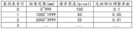
TABLE 1
The distance range refers to a distance range of the ranging result, that is, by obtaining the first ranging result, the distance range corresponding to the first ranging result in the lookup table may be searched, and at this time, the first search width corresponding to the first ranging result may be determined.
Step S2032: and determining a first light spot range according to the light spot center estimated value and a first search width corresponding to the first ranging result.
Specifically, the first light spot range is [ light spot center estimated value-first search width, light spot center estimated value + first search width]For example: assuming a first spot range of A1, the spot center estimate is The first ranging result is a TOF ranging value
 Then find the TOF range value in the lookup table
 The corresponding distance range, and thus the corresponding search width. Such as: when TOF range value
 1500mm, the first light spot range a1= [ cx _ pixel2-50, cx _ pixel2+50, if the search width is 50 pixels, which is applied to the distance range corresponding to the index 1]。
Further, in order to avoid an error of the first light spot range, the embodiment of the present application further adjusts the first light spot range by using the light spot characteristics in the first light spot range, so as to obtain the adjusted first light spot range.
Specifically, as shown in table 1 above, the lookup table further includes a corresponding relationship between the ranging result, the search width, and the spot characteristic adjustment parameter, and adjusts the first spot range according to the spot characteristic in the first spot range of the first image, so as to obtain the adjusted first spot range.
In the embodiment of the present application, the lookup table includes, but is not limited to, a distance or equivalent distance segment, i.e., a ranging result; the search boundary width of the corresponding segment, i.e. the search width; and searching boundary parameters which are correspondingly segmented and adjusted according to the light spot characteristics, namely light spot characteristic adjustment parameters.
Referring to fig. 4 again, fig. 4 is a schematic flow chart illustrating a process of adjusting the first light spot range according to an embodiment of the present disclosure;
as shown in fig. 4, adjusting the first spot range includes:
step S401: searching light spot characteristics in the first light spot range;
it can be understood that under the condition of the same material, the size of the light spot is in inverse proportion to the distance, so that different values can be set in the initial search range according to the distance, and the range is smaller when the distance is longer; meanwhile, under the same distance, the brightness and the size difference of the light spots hitting different materials are large and in direct proportion. Thus, in the embodiments of the present application, the spot characteristics include maximum brightness. And adjusting the search range according to the maximum brightness value in the search range, wherein the larger the maximum brightness is, the larger the search range is.
Step S402: determining a second search width according to the first search width by combining the light spot characteristics in the first light spot range and the light spot characteristic adjustment parameters corresponding to the first ranging result;
specifically, the second search width = the first search width + the spot feature adjustment parameter, for example: and if the spot feature is the maximum brightness value, the second search width = the first search width + the maximum brightness adjustment parameter. Suppose a maximum brightness value peak in the first spot rangemax=200, then as shown in table 1 above, when TOF ranging value 1500mm, the first search width is 50 pixels, the spot feature adjustment parameter is 0.05, and the second search width =50+200 × 0.05= 60.
Step S403: and determining the adjusted first light spot range according to the second search width.
Specifically, the adjusted first spot range = [ spot center estimated value-second search width, spot center estimated value + second search width ], for example: and the second search width is 60, the adjusted first spot range is [ spot center estimate-60, spot center estimate +60 ].
Step S204: searching a light spot boundary according to the first light spot range to determine a second light spot range;
specifically, the image in the first spot range is scanned to search for a spot boundary.
Referring to fig. 5 again, fig. 5 is a schematic view of a light spot boundary according to an embodiment of the present disclosure;
as shown in fig. 5, where the abscissa is the pixel index, i.e., the serial number corresponding to the pixel, and the ordinate is the luminance, the light spot boundary is the position where the luminance is abruptly changed.
In the embodiment of the present application, the manner of determining the boundary of the light spot includes, but is not limited to, setting a brightness threshold or a brightness gradient threshold, for example: the brightness threshold can be set to a fixed value or set to a percentage of the maximum brightness, and if the brightness exceeds the threshold, the light spot is formed, and the part which does not exceed the threshold is used as the light spot boundary.
Alternatively, the brightness gradient threshold needs to be set for each of the left and right sides, and may be set to a fixed value, or may be set to an extreme value, and then the position where the brightness change is the largest may be determined as the spot boundary.
It will be appreciated that the spot boundaries comprise two, and after searching for two spot boundaries, the position between the two spot boundaries is determined as the second spot range.
Step S205: determining a spot center calculation value of the ranging target in the first image according to the second spot range;
specifically, the image in the second spot range is calculated to determine the spot center calculation value of the ranging target in the first image. In the embodiment of the present application, the spot center calculation value is determined and obtained by processing a spot center algorithm, where the spot center algorithm includes, but is not limited to, a calculation method using brightness as a weight, a gaussian weighted centroid location method, and the like, and specifically, the gaussian weighted centroid location method includes: and performing Gaussian filtering on the gray value of the pixel of the image in the second light spot range to obtain a gray value calculation light spot center calculation value after the Gaussian filtering.
Step S206: and determining a second ranging result according to the calculated value of the center of the light spot, wherein the second ranging result is a final ranging result of the ranging target.
Specifically, determining a second ranging result according to the spot center calculation value includes:

wherein the content of the first and second substances, as a result of the second ranging measurement,
 is a first parameter of the plurality of parameters,
 as the second parameter, the parameter is,
 is the width of the picture element,
 the spot center is calculated.
It can be understood that the second ranging result is a ranging result calculated based on the first ranging result, and therefore the ranging accuracy of the second ranging result is higher than that of the first ranging result, and the spot center estimated value is determined by the first ranging result, and the spot center calculated value is further determined by the spot center estimated value to obtain the second ranging result.
In the embodiment of the application, the estimated value of the center of the light spot is determined by obtaining the first ranging result of the ranging target, so that the range of the first light spot is determined, the range of the second light spot is determined by utilizing the range of the first light spot, the calculated value of the center of the light spot is obtained, and the second ranging result is determined.
It should be understood that, referring to fig. 6a and fig. 6b together, fig. 6a is a schematic diagram of a spot splitting method according to an embodiment of the present disclosure; fig. 6b is a schematic diagram of an interference point according to an embodiment of the present application;
it can be understood that, as shown in fig. 6a, the splitting of the light spot easily causes the occurrence of a multi-peak phenomenon, which affects the accuracy of the range of the light spot, while, as shown in fig. 6b, when the interference light spot and the real light spot coexist, the interference light spot easily affects the accuracy of the position of the real light spot.
In the embodiment of the application, as the processing is carried out through the first ranging result, namely the TOF ranging value, the interference of light spot splitting can be avoided, and the interference light spots can be eliminated to obtain the estimated value of the light spot center position; selecting a proper possible light spot range according to the estimated value of the light spot center position; through a simple algorithm, the light spot boundary is searched, the accurate light spot center position is obtained through calculation, the distance measurement result is obtained through the triangle distance measurement principle, the whole calculation force requirement is reduced to the range which can be achieved by a low-cost single chip microcomputer, the embodiment of the application can obtain high distance measurement precision through small calculation amount, and the cost of the laser radar is reduced under the condition that the distance measurement precision is not reduced.
Specifically, please refer to fig. 7 again, fig. 7 is a schematic flow chart of another laser radar ranging method according to an embodiment of the present disclosure;
as shown in fig. 7, the ranging method of the laser radar includes:
step S701: calibrating the corresponding relation between the ranging result and the position of the light spot to establish a lookup table;
specifically, the look-up table includes: lookup table index, ranging result, search width and spot feature adjustment parameter, where the lookup table index is a sequence number in the lookup table, for example: the serial number is from 0 to N, the ranging result corresponds to a range, and the spot characteristic adjustment parameter corresponds to a spot characteristic, for example: the maximum brightness.
Step S702: calibrating parameters in a distance measurement formula;
specifically, the distance measurement formula includes a triangular distance measurement formula, and the parameter calibration in the distance measurement formula includes:
according to the triangulation distance measurement principle, a triangulation distance measurement formula can be obtained:

wherein the content of the first and second substances, 、
、 respectively a first parameter and a second parameter which need to be calibrated,
 is the width of the picture element, is constant for a fixed system,
 is the spot center position of the image sensor.
By obtaining the original calibration parameters and then obtaining two groups of theoretical distance values and actual distance measurement values, the first parameter and the second parameter after calibration can be obtained through solving.
Step S703: searching the lookup table according to the first ranging result to obtain a first search width corresponding to the first ranging result;
specifically, according to the distance range in which the first ranging result is located, the corresponding distance range is found from the lookup table, so that the first search width corresponding to the first ranging result is determined.
Step S704: determining a first light spot range according to the first ranging result and the first search width;
specifically, according to the first ranging result, the estimated value of the spot center of the ranging target in the first image is determined.
Suppose the ranging result is a TOF ranging value Then the range can be measured according to TOF
 And known parameters in the triangulation formula, the known parameters including a first parameter
 The second parameter
 And a pixel width
 The principle of obtaining the estimated value of the center of the light spot of the ranging target in the first image and calculating the estimated value of the center of the light spot according to the first ranging result is as follows:
formula for measuring distance by using pair of triangles Perform transformation and carry in ranging result
 Can deduce
 The calculation formula of (2) is as follows:

then it can be derived: determining a spot center estimated value of the ranging target in the first image according to the first ranging result, comprising:

wherein the content of the first and second substances, is the estimated value of the spot center of the ranging target in the first image,
 is a first parameter of the plurality of parameters,
 as the second parameter, the parameter is,
 as a result of the first ranging measurement,
 is the width of the pixel.
It will be appreciated that for a fixed system, the width of the picture elements Is a constant. The calibration parameters of the laser radar are calibrated in advance, wherein the first parameter
 And a second parameter
 All the parameters are calibrated parameters after the laser radar is calibrated.
Further, a first light spot range is determined according to the estimated value of the light spot center and the first search width, wherein the first light spot range is [ the estimated value of the light spot center-the first search width, the estimated value of the light spot center + the first search width ].
Step S705: obtaining an adjusted first light spot range according to the light spot characteristics in the first light spot range;
specifically, the light spot characteristics in the first light spot range are searched, the second search width is determined according to the first search width by combining the light spot characteristics in the first light spot range and the light spot characteristic adjustment parameters corresponding to the first ranging result, and the adjusted first light spot range is determined according to the second search width.
Step S706: searching a light spot boundary according to the adjusted first light spot range to determine a second light spot range;
specifically, the adjusted image of the first light spot range is scanned to search for a light spot boundary, and after two light spot boundaries are searched, the position between the two light spot boundaries is determined as the second light spot range.
Step S707: according to the second light spot range, determining a calculated value of the center of the forehead light spot of the ranging target in the first image;
specifically, the image in the second spot range is calculated to determine the spot center calculation value of the ranging target in the first image. In the embodiment of the present application, the spot center calculation value is determined and obtained by processing a spot center algorithm, where the spot center algorithm includes, but is not limited to, a calculation method using brightness as a weight, a gaussian weighted centroid location method, and the like, and specifically, the gaussian weighted centroid location method includes: and performing Gaussian filtering on the gray value of the pixel of the image in the second light spot range to obtain a gray value calculation light spot center calculation value after the Gaussian filtering.
Step S708: and determining a second ranging result according to the calculated value of the center of the light spot, wherein the second ranging result is a final ranging result of the ranging target.
Specifically, determining a second ranging result according to the spot center calculation value includes:

wherein the content of the first and second substances, as a result of the second ranging measurement,
 is a first parameter of the plurality of parameters,
 as the second parameter, the parameter is,
 is the width of the picture element,
 the spot center is calculated.
The method comprises the steps of establishing a lookup table by calibrating a corresponding relation between a ranging result and a spot position, further calibrating parameters in a ranging formula, determining a spot center estimated value according to a first ranging result of a ranging target, further determining a first spot range, obtaining the adjusted first spot range by using spot characteristics, determining a second spot range by using the adjusted first spot range, obtaining a spot center calculated value, and determining a second ranging result, wherein the second ranging result is a final ranging result of the ranging target.
In an embodiment of the present application, a ranging method for a laser radar is provided, including: acquiring a first ranging result of a ranging target; determining a light spot center estimated value of a ranging target in the first image according to the first ranging result; determining a first light spot range according to the first ranging result and the light spot center estimation value; searching a light spot boundary according to the first light spot range to determine a second light spot range; determining a spot center calculation value of the ranging target in the first image according to the second spot range; and determining a second ranging result according to the calculated value of the center of the light spot, wherein the second ranging result is a final ranging result of the ranging target. The estimated value of the center of the light spot is determined by obtaining the first ranging result of the ranging target, the range of the first light spot is further determined, the calculated value of the center of the light spot is obtained, the second ranging result is determined, and high ranging precision can be obtained through small calculated amount, so that the cost of the laser radar is reduced under the condition that the ranging precision is not reduced.
Referring to fig. 8, fig. 8 is a schematic structural diagram of a ranging apparatus of a laser radar according to an embodiment of the present disclosure;
the ranging device of the laser radar is applied to the laser radar, and particularly, the ranging device of the laser radar is applied to one or more processors of the laser radar.
As shown in fig. 8, the ranging apparatus 80 of the laser radar is applied to a laser radar installed in a robot, and includes:
a ranging result acquiring unit 801 configured to acquire a first ranging result of a ranging target;
a spot center estimating unit 802, configured to determine a spot center estimated value of a ranging target in the first image according to the first ranging result;
a first light spot range determining unit 803, configured to determine a first light spot range according to the first ranging result and the light spot center estimation value;
a second light spot range determining unit 804, configured to search a light spot boundary according to the first light spot range to determine a second light spot range;
a spot center calculating unit 805 configured to determine a spot center calculation value of the ranging target in the first image according to the second spot range;
a ranging result determining unit 806, configured to determine a second ranging result according to the spot center calculation value, where the second ranging result is a final ranging result of the ranging target.
In the embodiment of the present application, the distance measuring device of the laser radar may also be built by hardware devices, for example, the distance measuring device of the laser radar may be built by one or more than two chips, and the chips may work in coordination with each other to complete the distance measuring method of the laser radar described in the above embodiments. For another example, the distance measuring device of the laser radar may be constructed by various logic devices, such as a general processor, a Digital Signal Processor (DSP), an Application Specific Integrated Circuit (ASIC), a Field Programmable Gate Array (FPGA), a single chip, an arm (acorn RISC machine) or other programmable logic devices, discrete gate or transistor logic, discrete hardware components, or any combination of these components.
The ranging device of the laser radar in the embodiment of the present application may be a device, or may be a component, an integrated circuit, or a chip in a terminal. The device can be mobile electronic equipment or non-mobile electronic equipment. By way of example, the mobile electronic device may be a mobile phone, a tablet computer, a notebook computer, a palm top computer, a vehicle-mounted electronic device, a wearable device, an ultra-mobile personal computer (UMPC), a netbook or a Personal Digital Assistant (PDA), and the like, and the non-mobile electronic device may be a server, a Network Attached Storage (NAS), a Personal Computer (PC), a Television (TV), a teller machine or a self-service machine, and the like, and the embodiments of the present application are not particularly limited.
The ranging apparatus of the laser radar in the embodiment of the present application may be an apparatus having an operating system. The operating system may be an Android (Android) operating system, an ios operating system, or other possible operating systems, and embodiments of the present application are not limited specifically.
The ranging device of laser radar that this application embodiment provided can realize each process that figure 2 realized, for avoiding the repetition, no longer gives unnecessary details here.
It should be noted that the ranging device of the laser radar can execute the ranging method of the laser radar provided in the embodiment of the present application, and has the corresponding functional modules and beneficial effects of the execution method. For technical details that are not described in detail in the embodiments of the range finding apparatus for a laser radar, reference may be made to the range finding method for a laser radar provided in the embodiments of the present application.
In an embodiment of the present application, there is provided a ranging apparatus for a laser radar, the apparatus including: the ranging result acquisition unit is used for acquiring a first ranging result of a ranging target; the light spot center estimation unit is used for determining a light spot center estimation value of a ranging target in the first image according to the first ranging result; the first light spot range determining unit is used for determining a first light spot range according to the first ranging result and the light spot center estimation value; the second light spot range determining unit is used for searching the light spot boundary according to the first light spot range to determine a second light spot range; the light spot center calculating unit is used for determining a light spot center calculating value of the ranging target in the first image according to the second light spot range; and the ranging result determining unit is used for determining a second ranging result according to the calculated value of the center of the light spot, wherein the second ranging result is the final ranging result of the ranging target. The estimated value of the center of the light spot is determined by obtaining the first ranging result of the ranging target, the range of the first light spot is further determined, the range of the second light spot is determined by utilizing the range of the first light spot, the calculated value of the center of the light spot is obtained, the second ranging result is determined, and high ranging precision can be obtained through small calculated amount, so that the cost of the laser radar is reduced under the condition that the ranging precision is not reduced.
Fig. 9 shows a schematic diagram of a hardware structure of a laser radar according to an embodiment of the present application;
as shown in fig. 9, the lidar 90 includes at least one processor 901 and a memory 902 (a bus connection, one processor for example, in fig. 9) that are communicatively connected.
The estimated value of the center of the light spot is determined by obtaining the first ranging result of the ranging target, the range of the first light spot is further determined, the calculated value of the center of the light spot is obtained, the second ranging result is determined, and high ranging precision can be obtained through small calculated amount, so that the cost of the laser radar is reduced under the condition that the ranging precision is not reduced.
The memory 902, which is a non-transitory computer-readable storage medium, may be used to store non-transitory software programs, non-transitory computer-executable programs, and modules, such as program instructions/modules corresponding to the ranging method of the lidar in the embodiments of the present application. Processor 901 may implement the lidar ranging method in any of the method embodiments described below by executing non-transitory software programs, instructions, and modules stored in memory 902. In particular, memory 902 may include Volatile Memory (VM), such as Random Access Memory (RAM); the memory 902 may also include a non-volatile memory (NVM), such as a read-only memory (ROM), a flash memory (flash memory), a Hard Disk Drive (HDD) or a solid-state drive (SSD), or other non-transitory solid-state memory devices; the memory 902 may also comprise a combination of the above-described types of memory.
In embodiments of the application, the memory 902 may also include memory located remotely from the processor, which may be connected to the processor via a network. Examples of such networks include, but are not limited to, the internet, intranets, local area networks, mobile communication networks, and combinations thereof.
In this embodiment, the laser radar 90 may further include a wired or wireless network interface, a keyboard, an input/output interface, and other components to facilitate input and output, and the laser radar 90 may further include other components for implementing functions of the device, which is not described herein again.
Referring to fig. 10 again, fig. 10 is a schematic structural diagram of a robot according to an embodiment of the present disclosure;
as shown in fig. 10, the robot 100 includes: the system comprises a laser radar 101 and a controller 102, wherein the laser radar 101 is in communication connection with the controller 102, and the controller 102 is used for sending a ranging instruction to the laser radar 101 so as to enable the laser radar 101 to perform ranging. It will be appreciated that the ranging command may be sent by an external terminal to the robot 100, which is forwarded by the controller 102 to the lidar 101. The external terminal may be a fixed terminal or a mobile terminal, for example: electronic devices such as computers, mobile phones, tablets, etc., are not limited herein.
It should be noted that, for the specific hardware structure of the robot, reference may be made to the contents mentioned in the above embodiments, and details are not described herein again.
Embodiments of the present application also provide a computer-readable storage medium, such as a memory, including program code, which is executable by a processor to perform the ranging method of the lidar in the above embodiments. For example, the computer-readable storage medium may be a Read-Only Memory (ROM), a Random Access Memory (RAM), a Compact Disc Read-Only Memory (CDROM), a magnetic tape, a floppy disk, an optical data storage device, and the like.
Embodiments of the present application also provide a computer program product including one or more program codes stored in a computer readable storage medium. The processor of the electronic device reads the program code from the computer-readable storage medium, and the processor executes the program code to perform the method steps of the ranging method of the laser radar provided in the above-described embodiments.
It will be understood by those skilled in the art that all or part of the steps for implementing the above embodiments may be implemented by hardware, or may be implemented by hardware associated with program code, and the program may be stored in a computer readable storage medium, where the above mentioned storage medium may be a read-only memory, a magnetic or optical disk, etc.
Through the above description of the embodiments, those skilled in the art will clearly understand that each embodiment can be implemented by software plus a general hardware platform, and certainly can also be implemented by hardware. It will be understood by those skilled in the art that all or part of the processes of the methods of the embodiments described above can be implemented by hardware related to instructions of a computer program, which can be stored in a computer-readable storage medium, and when executed, can include the processes of the embodiments of the methods described above. The storage medium may be a magnetic disk, an optical disk, a Read-Only Memory (ROM), a Random Access Memory (RAM), or the like.
Finally, it should be noted that: the above embodiments are only used to illustrate the technical solutions of the present application, and not to limit the same; within the context of the present application, features from the above embodiments or from different embodiments may also be combined, steps may be implemented in any order, and there are many other variations of the different aspects of the present application as described above, which are not provided in detail for the sake of brevity; although the present application has been described in detail with reference to the foregoing embodiments, it should be understood by those of ordinary skill in the art that: the technical solutions described in the foregoing embodiments may still be modified, or some technical features may be equivalently replaced; and the modifications or the substitutions do not make the essence of the corresponding technical solutions depart from the scope of the technical solutions of the embodiments of the present application.
Claims (11)
1. A method of range finding for a lidar, the method comprising:
acquiring a first ranging result of a ranging target;
determining a light spot center estimated value of a ranging target in a first image according to the first ranging result;
determining a first light spot range according to the first ranging result and the light spot center estimation value;
searching a light spot boundary according to the first light spot range to determine a second light spot range;
determining a spot center calculation value of a ranging target in the first image according to the second spot range;
and determining a second ranging result according to the calculated value of the center of the light spot, wherein the second ranging result is a final ranging result of the ranging target.
2. The method of claim 1, wherein determining the spot center estimate for the ranging target in the first image based on the first ranging result comprises:

wherein the content of the first and second substances, is the estimated value of the spot center of the ranging target in the first image,
 is a first parameter of the plurality of parameters,
 as the second parameter, the parameter is,
 as a result of the first ranging measurement,
 is the width of the pixel.
3. The method of claim 1, further comprising:
and establishing a lookup table, wherein the lookup table comprises a corresponding relation between a ranging result and a search width, and the ranging result comprises a TOF ranging value.
4. The method of claim 3, wherein determining a first spot range based on the first ranging result and the spot center estimate comprises:
searching a first search width corresponding to the first ranging result according to the lookup table;
and determining a first light spot range according to the light spot center estimated value and a first search width corresponding to the first ranging result.
5. The method of claim 4, further comprising:
and adjusting the first light spot range according to the light spot characteristics in the first light spot range of the first image to obtain the adjusted first light spot range.
6. The method of claim 5, wherein the look-up table comprises a corresponding relationship between a range finding result, a search width and a spot characteristic adjustment parameter, and wherein adjusting the first spot range according to the spot characteristic in the first spot range of the first image to obtain an adjusted first spot range comprises:
searching for light spot characteristics in the first light spot range;
determining a second search width according to the first search width by combining the light spot characteristics in the first light spot range and the light spot characteristic adjustment parameters corresponding to the first ranging result;
and determining the adjusted first light spot range according to the second search width.
7. The method of claim 6, wherein the spot feature comprises a maximum brightness, wherein the spot feature adjustment parameter comprises a maximum brightness adjustment parameter, and wherein determining a second search width according to the first search width by combining the spot feature in the first spot range and the spot feature adjustment parameter corresponding to the first ranging result comprises:
the second search width = the first search width + maximum luminance × maximum luminance adjustment parameter.
8. The method according to any of claims 1-7, wherein determining a second ranging result based on the calculated spot center value comprises:

wherein the content of the first and second substances, as a result of the second ranging measurement,
 is a first parameter of the plurality of parameters,
 as the second parameter, the parameter is,
 is the width of the picture element,
 the spot center is calculated.
9. A ranging apparatus for a lidar, the apparatus comprising:
the ranging result acquisition unit is used for acquiring a first ranging result of a ranging target;
the spot center estimation unit is used for determining a spot center estimation value of a ranging target in the first image according to the first ranging result;
the first light spot range determining unit is used for determining a first light spot range according to the first ranging result and the light spot center estimated value;
the second light spot range determining unit is used for searching the light spot boundary according to the first light spot range to determine a second light spot range;
the light spot center calculating unit is used for determining a light spot center calculating value of the ranging target in the first image according to the second light spot range;
and the ranging result determining unit is used for determining a second ranging result according to the spot center calculation value, wherein the second ranging result is the final ranging result of the ranging target.
10. A lidar, comprising:
memory and one or more processors for executing one or more computer programs stored in the memory, the one or more processors, when executing the one or more computer programs, causing the lidar to implement the method of any of claims 1-8.
11. A robot, comprising:
the lidar of claim 10.
Priority Applications (1)
| Application Number | Priority Date | Filing Date | Title |
|---|---|---|---|
| CN202210274320.0A CN114371483B (en) | 2022-03-21 | 2022-03-21 | Laser radar ranging method and device, laser radar and robot |
Applications Claiming Priority (1)
| Application Number | Priority Date | Filing Date | Title |
|---|---|---|---|
| CN202210274320.0A CN114371483B (en) | 2022-03-21 | 2022-03-21 | Laser radar ranging method and device, laser radar and robot |
Publications (2)
| Publication Number | Publication Date |
|---|---|
| CN114371483A true CN114371483A (en) | 2022-04-19 |
| CN114371483B CN114371483B (en) | 2022-06-10 |
Family
ID=81145261
Family Applications (1)
| Application Number | Title | Priority Date | Filing Date |
|---|---|---|---|
| CN202210274320.0A Active CN114371483B (en) | 2022-03-21 | 2022-03-21 | Laser radar ranging method and device, laser radar and robot |
Country Status (1)
| Country | Link |
|---|---|
| CN (1) | CN114371483B (en) |
Cited By (2)
| Publication number | Priority date | Publication date | Assignee | Title |
|---|---|---|---|---|
| CN115372933A (en) * | 2022-08-31 | 2022-11-22 | 深圳市欢创科技有限公司 | Stray light filtering method and device and laser radar |
| CN115656978A (en) * | 2022-10-31 | 2023-01-31 | 哈尔滨工业大学 | Method and device for obtaining light spot position in target stripe image |
Citations (12)
| Publication number | Priority date | Publication date | Assignee | Title |
|---|---|---|---|---|
| CN102401647A (en) * | 2010-09-07 | 2012-04-04 | 原相科技股份有限公司 | Optical ranging system |
| CN105652280A (en) * | 2015-11-26 | 2016-06-08 | 广东雷洋智能科技股份有限公司 | Laser radar triangulation ranging method |
| CN106092146A (en) * | 2016-08-30 | 2016-11-09 | 宁波菜鸟智能科技有限公司 | Laser ranging bearing calibration and system |
| CN107870323A (en) * | 2017-11-06 | 2018-04-03 | 深圳市杉川机器人有限公司 | De-jittering method and device |
| CN109964144A (en) * | 2016-11-17 | 2019-07-02 | 特里纳米克斯股份有限公司 | Detector at least one object of optical detection |
| CN110687545A (en) * | 2019-09-27 | 2020-01-14 | 电子科技大学中山学院 | High-precision laser radar system |
| CN111103593A (en) * | 2019-12-31 | 2020-05-05 | 深圳市欢创科技有限公司 | Distance measurement module, robot, distance measurement method and non-volatile readable storage medium |
| CN111819468A (en) * | 2020-03-16 | 2020-10-23 | 深圳市汇顶科技股份有限公司 | Three-dimensional image sensing system, related electronic device and time-of-flight distance measurement method |
| US20210165098A1 (en) * | 2019-12-01 | 2021-06-03 | Magik Eye Inc. | Enhancing triangulation-based three-dimensional distance measurements with time of flight information |
| CN113176579A (en) * | 2021-03-01 | 2021-07-27 | 奥比中光科技集团股份有限公司 | Light spot position self-adaptive searching method, time flight ranging system and ranging method |
| CN113466836A (en) * | 2021-06-23 | 2021-10-01 | 深圳市欢创科技有限公司 | Distance measurement method and device and laser radar |
| WO2021213788A1 (en) * | 2020-04-21 | 2021-10-28 | Daimler Ag | Method and device for identifying blooming in a lidar measurement |
-
2022
- 2022-03-21 CN CN202210274320.0A patent/CN114371483B/en active Active
Patent Citations (12)
| Publication number | Priority date | Publication date | Assignee | Title |
|---|---|---|---|---|
| CN102401647A (en) * | 2010-09-07 | 2012-04-04 | 原相科技股份有限公司 | Optical ranging system |
| CN105652280A (en) * | 2015-11-26 | 2016-06-08 | 广东雷洋智能科技股份有限公司 | Laser radar triangulation ranging method |
| CN106092146A (en) * | 2016-08-30 | 2016-11-09 | 宁波菜鸟智能科技有限公司 | Laser ranging bearing calibration and system |
| CN109964144A (en) * | 2016-11-17 | 2019-07-02 | 特里纳米克斯股份有限公司 | Detector at least one object of optical detection |
| CN107870323A (en) * | 2017-11-06 | 2018-04-03 | 深圳市杉川机器人有限公司 | De-jittering method and device |
| CN110687545A (en) * | 2019-09-27 | 2020-01-14 | 电子科技大学中山学院 | High-precision laser radar system |
| US20210165098A1 (en) * | 2019-12-01 | 2021-06-03 | Magik Eye Inc. | Enhancing triangulation-based three-dimensional distance measurements with time of flight information |
| CN111103593A (en) * | 2019-12-31 | 2020-05-05 | 深圳市欢创科技有限公司 | Distance measurement module, robot, distance measurement method and non-volatile readable storage medium |
| CN111819468A (en) * | 2020-03-16 | 2020-10-23 | 深圳市汇顶科技股份有限公司 | Three-dimensional image sensing system, related electronic device and time-of-flight distance measurement method |
| WO2021213788A1 (en) * | 2020-04-21 | 2021-10-28 | Daimler Ag | Method and device for identifying blooming in a lidar measurement |
| CN113176579A (en) * | 2021-03-01 | 2021-07-27 | 奥比中光科技集团股份有限公司 | Light spot position self-adaptive searching method, time flight ranging system and ranging method |
| CN113466836A (en) * | 2021-06-23 | 2021-10-01 | 深圳市欢创科技有限公司 | Distance measurement method and device and laser radar |
Non-Patent Citations (5)
| Title |
|---|
| MANESH V. MOHAN等: "A Method for Minimum Range Extension with Improved Accuracy in Triangulation Laser Range Finder", 《PROCEEDINGS OF THE 1ST INTERNATIONAL CONFERENCE ON WIRELESS TECHNILOGIES FOR HUMANITARIAN RELIEF》 * |
| ORESTE SGROTT等: "A 134-Pixel CMOS Sensor for Combined Time-of-Flight and Optical Triangulation 3-D Imaging", 《IEEE JOURNAL OF SOLID-STATE CIRCUITS》 * |
| YASSINE SELAMI等: "A Scheme for Enhancing Precision in 3-Dimensional Positioning for Non-Contact Measurement Systems Based on Laser Triangulation", 《SENSORS》 * |
| 侯良策: "基于激光三角法的室内测距系统研究", 《中国优秀博硕士学位论文全文数据库(硕士)信息科技辑(月刊)》 * |
| 张正琦等: "激光三角测距中的光斑形状修正", 《光学精密工程》 * |
Cited By (2)
| Publication number | Priority date | Publication date | Assignee | Title |
|---|---|---|---|---|
| CN115372933A (en) * | 2022-08-31 | 2022-11-22 | 深圳市欢创科技有限公司 | Stray light filtering method and device and laser radar |
| CN115656978A (en) * | 2022-10-31 | 2023-01-31 | 哈尔滨工业大学 | Method and device for obtaining light spot position in target stripe image |
Also Published As
| Publication number | Publication date |
|---|---|
| CN114371483B (en) | 2022-06-10 |
Similar Documents
| Publication | Publication Date | Title |
|---|---|---|
| CN108762245B (en) | Data fusion method and related equipment | |
| CN114371483B (en) | Laser radar ranging method and device, laser radar and robot | |
| KR102032070B1 (en) | System and Method for Depth Map Sampling | |
| CN106569225B (en) | Unmanned vehicle real-time obstacle avoidance method based on ranging sensor | |
| CN112051575B (en) | Method for adjusting millimeter wave radar and laser radar and related device | |
| CN114355321B (en) | Laser radar calibration method, device and system, laser radar and robot | |
| CN103065323A (en) | Subsection space aligning method based on homography transformational matrix | |
| CN115656984A (en) | TOF point cloud processing method, point cloud optimization method, laser radar and robot | |
| US20200206927A1 (en) | Relocalization method and robot using the same | |
| EP4260092A1 (en) | Method, apparatus and radar system for tracking objects | |
| CN111308415B (en) | Online pose estimation method and equipment based on time delay | |
| WO2022179207A1 (en) | Window occlusion detection method and apparatus | |
| JP2023503750A (en) | ROBOT POSITIONING METHOD AND DEVICE, DEVICE, STORAGE MEDIUM | |
| CN117289300A (en) | Point cloud correction method, laser radar and robot | |
| CN115032618B (en) | Blind area repairing method and device applied to laser radar and laser radar | |
| CN116449329A (en) | Method, system, equipment and storage medium for disambiguating speed of millimeter wave radar | |
| WO2022160879A1 (en) | Method and apparatus for determining conversion parameters | |
| WO2022037370A1 (en) | Motion estimation method and apparatus | |
| CN114815809A (en) | Obstacle avoidance method and system for mobile robot, terminal device and storage medium | |
| Lu et al. | a Low-Cost Visual Radar-Based Odometry Framework with Mmwave Radar and Monocular Camera | |
| Qidan et al. | A rapid and precise self-localization approach of mobile robot based on binocular omni-directional vision | |
| Basit et al. | Joint localization and target tracking with a monocular camera | |
| Wang et al. | Infradar-Localization: single-chip infrared-and radar-based Monte Carlo localization | |
| Gireesha et al. | Lane Change Assistance Using LiDAR for Autonomous Vehicles | |
| Taylor et al. | Parameterless automatic extrinsic calibration of vehicle mounted lidar-camera systems |
Legal Events
| Date | Code | Title | Description |
|---|---|---|---|
| PB01 | Publication | ||
| PB01 | Publication | ||
| SE01 | Entry into force of request for substantive examination | ||
| SE01 | Entry into force of request for substantive examination | ||
| GR01 | Patent grant | ||
| GR01 | Patent grant | ||
| CP03 | Change of name, title or address |
Address after: 518000, Floor 1801, Block C, Minzhi Stock Commercial Center, North Station Community, Minzhi Street, Longhua District, Shenzhen City, Guangdong Province Patentee after: Shenzhen Huanchuang Technology Co.,Ltd. Address before: 518000 2407-2409, building 4, phase II, Tian'an Yungu Industrial Park, Gangtou community, Bantian street, Longgang District, Shenzhen, Guangdong Patentee before: SHENZHEN CAMSENSE TECHNOLOGIES Co.,Ltd. |
|
| CP03 | Change of name, title or address |