Disclosure of Invention
Based on the technical problems, the invention provides an air storage type elevator car device and a control method thereof, which are used for solving the problem that passengers are cross-infected by germs in an elevator and ensuring that the fresh air is supplied in the elevator car when the elevator is in a fire alarm state.
The invention adopts the specific technical scheme that: an air storage type elevator car device comprises a car body, an air storage and supply component, a spray component, an exhaust component and a control system, the air storage and supply component is arranged at the top of the car body and is provided with an air inlet machine, an air compressor and a pressure air storage tank, the air inlet machine is provided with an air filtering device, the pressure air storage tank is provided with a sterilizing device, the air inlet machine supplies air to the air compressor, the air compressor charges pressure gas into the pressure gas storage tank, the pressure gas storage tank conveys clean air to the interior of the lift car through the air outlet pipe, the spraying assembly is arranged on one outer side wall of the lift car main body, used for spraying disinfectant to the elevator shaft, the exhaust assembly is arranged at the lower part of the outer side surface of the car body, the exhaust assembly is used for sucking out turbid air in the car, and the control system controls the air storage and supply assembly and the exhaust assembly to act together so that the inside of the car is in a negative pressure state when the car door is closed.
Furthermore, the air storage and supply assembly is mounted on the air supply assembly mounting plate, the side wall of the pressure air storage tank is provided with an air inlet hole arranged at the middle position and air outlet holes arranged at two sides of the air inlet hole, the air inlet hole is communicated with an air inlet pipe of the air compressor, the air outlet holes are connected with one end of an air outlet pipe, and the air outlet pipe is a pipe
The shape, the other end that goes out the tuber pipe is connected with the air inlet mouth of pipe on the air supply subassembly mounting panel, the air supply subassembly mounting panel is installed at the car frame top, roof in the car is installed to car frame top inboard, roof is the transparent plastic material in the car, roof and car frame top and roof form an enclosure space in the car, the array equipartition has a plurality of supply-air holes on the roof in the car.
Further, the gas storage pressure of the pressure gas storage tank is 0.8Mpa to 1.2Mpa, the pressure gas storage tank is a cuboid, two baffles are vertically arranged in the pressure gas storage tank, the baffles divide the pressure gas storage tank into three relatively independent spaces along the length direction, an air inlet pipe of the air compressor is connected with a middle cavity, and an air outlet pipe is communicated with the cavities on two sides, wherein a gap is formed between the upper part of each baffle and a top plate of the pressure gas storage tank, so that the gas in the middle cavity can flow to the cavities on two sides; the disinfectant nozzle is arranged in the middle cavity, the sterilizing light sources are arranged in the cavities on the two sides, and the disinfectant nozzle is an ultrasonic vibration atomizer.
Further, the exhaust assembly comprises an exhaust fan, an exhaust pipe, a left gas collecting hood and a right gas collecting hood, the left gas collecting hood and the right gas collecting hood are symmetrically arranged in structure, the exhaust assembly is arranged on two car side outer plates on the outer side of the car frame side, side outer plate exhaust ports are formed in the middle of the lower portion of each car side outer plate, the left gas collecting hood and the right gas collecting hood are respectively fixed on the exhaust ports of the two side outer plates, a car side inner plate is arranged on the inner side of the car frame side, and a plurality of side inner plate exhaust holes are formed in the lower portion array of the car side inner plate.
Furthermore, the exhaust pipe is integrally U-shaped, the left gas collecting hood and the right gas collecting hood are respectively connected with two arms of the U-shape, the exhaust fan is connected with the middle part of the exhaust pipe, and an exhaust fan outlet which is arranged downwards is formed in the exhaust fan; the side outer plate exhaust port is separated by the car frame side column, the left gas collecting hood and the right gas collecting hood are provided with gas collecting hood bodies, the gas collecting hood bodies are provided with two branch pipes along the length direction, and the two branch pipes corresponding to the side outer plate exhaust port separated by the car frame side column are connected with the collecting pipe.
Further, the spraying subassembly passes through the fixing base and connects on car side planking, the spraying subassembly includes the spray tube, sets up annotate the liquid mouth, set up the disinfectant liquid reserve tank between car side inner panel and car side inner panel on car side inner panel, the spray tube includes vertical pipe, sets up the pipette at vertical pipe middle part and sets up the horizontal pipe at vertical pipe both ends, the pipette is connected with the disinfectant liquid reserve tank, the horizontal pipe at both ends is connected with shower nozzle and lower shower nozzle respectively.
Further, the pipette is the type of falling L, it has transparent cover to annotate the liquid mouth, transparent cover installs on the inner panel opening of car side inner panel, the level gauge has on the disinfectant liquid reserve tank, it is ultrasonic vibration atomizer to go up the shower nozzle and be with lower shower nozzle, it works when the elevator goes upward to go up the shower nozzle, lower shower nozzle works when the elevator goes downward.
Furthermore, a visual sensor for identifying the number of people in the elevator is arranged in the elevator car, and the control system adjusts the air inlet amount of the air storage and supply component and the air outlet amount of the exhaust component according to the number of people in the elevator; a first smoke sensor is arranged in the left gas collecting hood and the right gas collecting hood, a loudspeaker is also arranged in the elevator, and the loudspeaker gives out an alarm sound after the first smoke sensor senses a smoke signal; and a second smoke sensor is also arranged on the air inlet machine and used for sensing the air state of the elevator hoistway.
Further, a control method of the air storage type elevator car is provided, which comprises the following steps:
s1, the control system acquires the air state information in the elevator shaft and simultaneously acquires the personnel and air quality information in the elevator car;
s2, judging the air state in the elevator shaft according to S, and controlling the pressure air storage tank of the air storage and supply component to charge air or stop charging air;
s3, on the basis of S, the control system controls whether the air storage and supply assembly supplies air or not according to the condition of the personnel in the car acquired by the vision sensor and controls whether the exhaust assembly inhales air or not;
s4, controlling an upper spray head or a lower spray head of the spray assembly to release disinfectant to an elevator shaft according to whether the elevator runs in a manned mode;
and S5, when the elevator runs, the air storage and supply component charges the pressure air storage tank to a preset pressure.
Further, in steps S2 to S5, the germicidal light source inside the pressurized air tank is always turned on.
Compared with the prior art, the invention has the technical effects that: the negative pressure state of the lift car can be realized by arranging the air storage and supply assembly and the exhaust assembly, air is stored in advance by the air storage and supply assembly and is disinfected during the storage period, purified and disinfected air is conveyed into the lift car by the air storage and supply assembly, dirty air in the lift is discharged out of the lift car by the exhaust assembly, the probability of cross infection of personnel in the lift car is reduced, the disinfection and sterilization of a shaft can be realized by the spray assembly, the quality of air sucked by the air storage and supply assembly is ensured, meanwhile, a pressure air storage tank of the air storage and supply assembly can store a certain amount of air in a low pressure state, and when the lift meets emergency conditions such as fire alarm and the like, the suction of smoke in the shaft can be stopped, so that air supply in the pressure tank is used, and the rescue time is won for fire fighters.
Drawings
In order to more clearly illustrate the technical solutions of the embodiments of the present invention, the drawings needed to be used in the embodiments of the present invention or in the description of the prior art will be briefly described below, and it is obvious that the drawings described below are only some embodiments of the present invention, and it is obvious for those skilled in the art that other drawings can be obtained according to the drawings without creative efforts.
Fig. 1 is a schematic view of the whole structure of an elevator car of the invention;
FIG. 2 is a schematic view of the overall structure of an elevator car according to the present invention;
FIG. 3 is a schematic diagram of the air storage and supply assembly of the present invention;
FIG. 4 is a structural view of the pressure air tank of the present invention;
fig. 5 is an internal structural view of the pressure air container of the present invention;
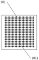
FIG. 6 is a top plan view of the inside of the car of the present invention;
FIG. 7 is a view of the mounting plate of the blowing assembly of the present invention;
FIG. 8 is a structural relationship diagram between the car inner ceiling and the blower assembly mounting plate of the present invention;
FIG. 9 is a side outer panel structure of the car of the present invention;
FIG. 10 is a block diagram of the exhaust assembly of the present invention;
fig. 11 is a block diagram of a gas skirt of the present invention;
FIG. 12 is a block diagram of a spray assembly of the present invention;
fig. 13 is a view showing the inside structure of the car of the present invention;
FIG. 14 is a view of the nozzle of the present invention;
fig. 15 is a side internal structure view of the car of the present invention.
Description of reference numerals:
10. a car body; 101. a car inner roof; 1011. an air supply hole; 1011. air supply bar holes; 102. a car frame top rail; 103. a car side outer panel; 1031. a side outer plate exhaust port; 104. a car-side inner panel; 1041. side inner plate exhaust holes; 1042. an inner plate opening; 105. car frame side uprights;
20. the air storage and supply component; 201. a pressure gas storage tank; 2011. an air outlet; 2012. an air inlet; 2013. a top plate; 2014. a baffle plate; 202. an air inlet machine; 203. an air compressor; 204. an air outlet pipe; 205. an air inlet pipe; 206. an air supply assembly mounting plate; 2061. an air inlet pipe orifice; 207. a germicidal light source; 208. a disinfectant nozzle;
30. a spray assembly; 301. a nozzle; 3011. a vertical tube; 3012. a pipette; 3013. a horizontal tube; 3014. an upper spray head; 3015. a lower nozzle; 3016. a fixed seat; 302. a liquid injection port; 303. a disinfectant liquid storage tank;
40. an exhaust assembly; 401. an exhaust fan; 4011. an exhaust fan outlet; 402. an exhaust pipe (U-shaped); 403. a left gas-collecting channel; 404. a right gas-collecting channel; 4041. a gas-collecting hood body; 4042. a branch pipe; 4043. a header; 4044. a smoke sensor;
50. a control system; 501. a first smoke sensor; 502. a second smoke sensor; 503. a vision sensor; 504. a loudspeaker.
Detailed Description
Reference will now be made in detail to embodiments of the present invention, examples of which are illustrated in the accompanying drawings, wherein like or similar reference numerals refer to the same or similar elements or elements having the same or similar function throughout. The embodiments described below with reference to the drawings are illustrative and intended to be illustrative of the invention and are not to be construed as limiting the invention. The specific meanings of the above terms in the present invention can be understood by those skilled in the art according to specific situations.
In order to make the objects, technical solutions and advantages of the present invention more apparent, the present invention is described in further detail below with reference to the accompanying drawings and embodiments.
The invention is implemented in detail as follows, the negative pressure state of the lift car can be realized, air is stored in advance through the air storage and supply assembly, air in the storage tank is used for supplying air to the lift car, the air is disinfected during the storage period, and meanwhile, the disinfection and sterilization of the well can be realized. Specifically, as shown in fig. 1 to 15, a gas storage type elevator car device comprises a car body 10, a gas storage air supply assembly 20, a spraying assembly 30, an exhaust assembly 40 and a control system 50, wherein the gas storage air supply assembly 20 is arranged at the top of the car body 10, the gas storage air supply assembly 20 comprises an air inlet machine 202, an air compressor 203 and a pressure gas storage tank 201, the air inlet machine 202 comprises an air filter device, the air filter device adopts the prior art, such as filter cotton, activated carbon or plasma sterilization and filtration modes, a sterilization device is arranged in the pressure gas storage tank 201, the air inlet machine 202 supplies air to the air compressor 203, the air compressor 203 charges pressure gas into the pressure gas storage tank 201, the pressure gas storage tank 201 conveys clean air to the inside of the car through an air outlet pipe 204, the spraying assembly 30 is arranged on an outer side wall of the car body 10, the air exhaust assembly 40 is arranged at the lower part of the outer side surface of the car body 10, the exhaust assembly 40 is used for sucking turbid air in the car, and the control system 50 controls the air storage and supply assembly 20 and the exhaust assembly 40 to act together so that the interior of the car is in a negative pressure state when the car door is closed, i.e. the air exhaust amount of the car can be ensured to be larger than the air intake amount.
Further, the air storage and supply assembly 20 is installed on the air supply assembly mounting plate 206, the side wall of the pressure air storage tank 201 is provided with an air inlet 2012 arranged at the middle position and an air outlet 2011 arranged at two sides of the air inlet 2012, the air inlet 2012 is communicated with the air inlet pipe 205 of the air compressor 203, the air outlet 2011 is connected with one end of the air outlet pipe 204, the air outlet pipe 204 is an air outlet pipe 204

The other end of the air outlet pipe 204 is connected with an air inlet pipe mouth 2061 on the air supply assembly mounting plate 206, the air supply assembly mounting plate 206 is mounted at the top of a car frame, the car frame mainly refers to a frame of a car, the car frame is mainly formed by various section steels, and the inner side and the outer side of the frame are provided with covering plates, as shown in fig. 8, the inner side of the top of the car frame is provided with a car inner top plate 101, the car inner top plate 101 is made of transparent plastic materials, the car inner top plate 101, a car frame top cross rod 102 at the top of the car frame and the car inner top plate 101 form a closed space, a plurality of air supply holes 1011 are uniformly distributed in an array on the car inner top plate 101, and the air supply holes 1011 are preferably circular, and can also be rectangular, strip-shaped or kidney-shaped. The enclosed space in install the light, use transparent material can not influence the illumination, guarantee the air feed simultaneously. As shown in fig. 6, the array of
air holes 1011 is mainly used to ensure that the air flow is uniform when the air is supplied downwards from the top of the car, so that passengers do not feel that a large amount of air is blown to the top of the car.
Further, the gas storage pressure of the pressure gas storage tank 201 is 0.8Mpa to 1.2Mpa, the pressure gas storage tank 201 is preferably a rectangular parallelepiped, and a cylindrical gas storage container can also be used, two baffles 2014 are vertically arranged in the pressure gas storage tank 201, the baffles 2014 divide the pressure gas storage tank 201 into three relatively independent spaces along the length direction, the air inlet pipe 205 of the air compressor 203 is connected with the middle chamber, the air outlet pipe 204 is communicated with the chambers on both sides, wherein a gap is formed between the upper part of the baffle 2014 and the top plate 2013 of the pressure gas storage tank 201, so that the gas in the middle chamber can flow to the chambers on both sides, and the air flow direction in the pressure gas storage tank 201 is as shown in fig. 5; the middle chamber is internally provided with a disinfectant nozzle 208, the disinfectant nozzle 208 adopts an ultrasonic vibration atomizer, the disinfectant is preferably hydrogen peroxide, the middle chamber is equivalent to a buffer chamber, the buffer chamber is internally sterilized for the first time, the two side chambers are internally provided with sterilizing light sources 207, and the sterilizing light sources 208 are preferably LED ultraviolet lamps. The germicidal light source 207 and the disinfectant nozzle 208 constitute a germicidal device.
It is worth noting that compared with the method of directly sterilizing the air after filtering, the method of sterilizing the air in the pressure air storage tank 201 has the advantages that the sterilization is thorough, and the sterilization device can be in a moving state all the time without influencing passengers to take the elevator, and is not limited by whether the elevator car is occupied or not; meanwhile, when no person is in the car, the sterilization device can sterilize the air in the pressure air storage tank 201 all the time, and the completely sterilized air is supplied to the car through the air inlet pipe 205, so that the sterilization effect is good, and the air flow is stable and adjustable.
Simultaneously, use pressure gas holder 201 storage air can regard as emergent air supply to the clean air of car supply, especially the elevartor shaft meets the fire alarm time, be full of the flue gas in the elevartor shaft, the elevator is not suitable for taking, and use pressure gas holder 201 time, when sensing to have the flue gas in the well, stop air inlet machine 202 and extract the well air, stop to exhaust to the outside simultaneously, pressure gas holder 201 directly supplies air to the car, because pressure gas holder 201 is a pressure vessel, can store more clean air, and this clean air can guarantee the air feed of certain time, personnel's safety in the car has been guaranteed, thereby win the rescue time for the fire fighter.
Further, the exhaust assembly 40 includes an exhaust fan 401, an exhaust pipe 402, a left gas collecting channel 403 and a right gas collecting channel 404, the left gas collecting channel 403 and the right gas collecting channel 404 are symmetrically arranged, the exhaust assembly 40 is disposed on two car side outer plates 103 on the outer sides of the car frame side portions, side outer plate exhaust ports 1031 are disposed in the middle of the lower portions of the car side outer plates 103, the left gas collecting channel 403 and the right gas collecting channel 404 are respectively fixed on the two side outer plate exhaust ports 1031, a car side inner plate 104 is disposed on the inner side of the car frame side portion, and a plurality of side inner plate exhaust holes 1041 are disposed in the lower array of the car side inner plate 104. A closed area is formed between the car side outer plate 103 and the car side inner plate 104, and the left gas collecting hood 403 and the right gas collecting hood 404 can discharge air in the car to the hoistway through the side inner plate exhaust hole 1041 and the side outer plate exhaust port 1031.
Further, the exhaust pipe 402 is U-shaped as a whole, the left gas collecting hood 403 and the right gas collecting hood 404 are respectively connected with two arms of the U-shape, the exhaust fan 401 is connected with the middle part of the exhaust pipe 402, and the exhaust fan 401 is provided with an exhaust fan outlet 4011 which is arranged downwards, so that the air inlet machine 202 is arranged at the upper part of the car, in order to prevent the air inlet machine 202 from sucking the gas exhausted by the exhaust fan 401, the exhaust fan outlet 4011 is specially arranged downwards, and the suction of too much dirty air is reduced as much as possible; the left gas collecting hood 403 and the right gas collecting hood 404 have gas collecting hood bodies 4041, and the side outer panel exhaust port 1031 is partitioned by the car frame side column 105, so that the gas collecting hood bodies 4041 are provided with two branch pipes 4042 along the length direction, the two branch pipes 4042 are connected to a header 4043 corresponding to the side outer panel exhaust port 1031 partitioned by the car frame side column 105, and the header 4043 is further connected to the exhaust pipe 402. Meanwhile, the outlet 4011 of the exhaust fan is also provided with a filtering device such as an air intake fan 202, which can reduce bacteria discharged into the hoistway.
Further, in order to further sterilize germs discharged into the hoistway, the spraying assembly 30 is connected to the car side outer plate 103 through a fixing seat 3016, the spraying assembly 30 comprises a spraying pipe 301, a liquid injection port 302 arranged on the car side inner plate 104, and a disinfectant liquid storage tank 303 arranged between the car side inner plate 104 and the car side inner plate 104, the adopted disinfectant is mainly hydrogen peroxide or alcohol, the spraying pipe 301 comprises a vertical pipe 3011, a liquid suction pipe 3012 arranged in the middle of the vertical pipe 3011, and horizontal pipes 3013 arranged at two ends of the vertical pipe 3011, the liquid suction pipe 3012 is connected with the disinfectant liquid storage tank 303 and used for sucking the disinfectant from the liquid storage tank 303, and the horizontal pipes 3013 at the two ends are respectively connected with an upper spray head 3014 and a lower spray head 3015.
Further, the pipette 3012 is of an inverted L shape, the liquid injection port 302 is provided with a transparent cover plate, the transparent cover plate is mounted on an inner plate opening 1042 of the car side inner plate 104, the disinfectant liquid storage tank 303 is provided with a liquid level meter, the surplus of the disinfectant liquid storage tank 303 can be observed through the transparent cover plate, the disinfectant liquid is conveniently added from the inside of the car directly, the upper spray head 3014 and the lower spray head 3015 are ultrasonic vibration atomizing spray heads, and the sprayed disinfectant is in a fine mist shape and cannot generate large liquid drops, so that the situation that the humidity of an elevator hoistway is too high and the working environment of the elevator is affected is avoided; meanwhile, the control system 50 controls the upper spray head 3014 to work when the elevator goes downwards, and the lower spray head 3015 to work when the elevator goes upwards, so that the disinfectant can be prevented from being sprayed onto the car body 10.
Furthermore, a visual sensor 503 for identifying the number of passengers in the elevator is arranged in the elevator car, and the visual sensor 503 is used for identifying the number of passengers in the elevator car and judging the crowdedness degree of the elevator car; the control system 50 adjusts the air intake of the air storage and supply component 20 and the air exhaust of the air exhaust component 40 according to the number of people in the elevator; the number of people is more than months, the air supply quantity is larger, the air exhaust quantity is also larger, but the air exhaust quantity still needs to be larger than the air supply quantity, so that the negative pressure state of the lift car can be ensured;
in addition, in view of the fact that some passengers smoke in the elevator, the health of other people is seriously affected and the safe operation of the elevator is seriously affected, the smoke sensors I501 are arranged in the left gas collecting hood 403 and the right gas collecting hood 404, the elevator is also internally provided with a loudspeaker 504, and after the smoke sensors I501 sense smoke signals, the loudspeaker 504 gives out alarm sound and prompt sound to prompt the passengers to avoid smoking in the elevator car; meanwhile, the first smoke sensor 501 is also used for sensing other types of smoke, such as smoke caused by circuit failure.
In addition, in order to ensure that a large amount of smoke is collected in the elevator shaft when the elevator encounters a fire alarm, the air inlet machine 202 is further provided with a smoke sensor II 502 for sensing the air state of the elevator shaft, when the smoke in the shaft is detected, the control system 50 controls the air inlet machine 202 and the air compressor 203 to stop supplying air to the pressure air storage tank 201, the air is supplied to the car only by the air stored in the pressure air storage tank 201, and meanwhile, the exhaust component 40 is stopped to exhaust air outside the car, so that the oxygen storage amount in the car can be ensured.
Further, a control method of the air storage type elevator car is provided, which comprises the following steps:
s1, the control system 50 obtains the air state information in the elevator shaft, and obtains the information of the personnel and the air quality in the elevator car, mainly obtains the number and the crowdedness of the personnel in the elevator car through the vision sensor 503, and obtains the air quality in the elevator car through the smoke sensor 501;
s2, judging the air state in the elevator shaft according to S1, and controlling the pressure air tank 201 of the air storage and supply component 20 to charge air or stop charging air; if the well air is normal, the air storage and supply assembly 20 is inflated, and if abnormal states such as smoke and the like are detected, the inflation of the pressure air storage tank 201 is stopped, so that the air quality in the pressure air storage tank 201 is ensured.
S3, on the basis of S2, the control system 50 controls whether the air storage and supply assembly 20 supplies air or not and controls whether the exhaust assembly 40 inhales air or not according to the condition of the person in the car acquired by the visual sensor 503, when the person takes the car, the air storage and supply assembly 20 supplies air to the car, and the exhaust assembly 40 exhausts air, wherein the exhaust air volume is larger than the air supply volume; when the elevator is empty, the air supply is stopped, but the exhaust assembly 40 still works, and the air in the elevator car is ensured to be exhausted.
S4, controlling an upper spray head 3014 or a lower spray head 3015 of the spray assembly 30 to release disinfectant to the elevator shaft according to whether the elevator runs in a manned mode, specifically, controlling the elevator to move upwards, the lower spray head 3015 to work, controlling the elevator to move downwards, and controlling the upper spray head 3014 to work;
s5, when the elevator runs, the air storage and supply assembly 20 inflates the pressure air storage tank 201 to a preset pressure so that enough purified air can be supplied to the elevator car when passengers are available next time, specifically, the air compressor 203 is started to inflate the pressure air storage tank 201 when the pressure is lower than 0.8Mpa, and the inflation is stopped when the pressure reaches 1.2 Mpa.
Further, in steps S2 to S5, the germicidal light source 207 inside the pressurized air tank 201 is always turned on, and the disinfectant nozzle 208 starts spraying disinfectant into the pressurized air tank 201 when sensing a pressure drop of the pressurized air tank 201, and stops spraying disinfectant when the pressure reaches 1.2 MPa.
The invention can realize the negative pressure state of the lift car, pre-store the air through the air storage and supply assembly, sterilize the air during the storage period and realize the sterilization of the well.
The above description is only for the purpose of illustrating the preferred embodiments of the present invention and is not to be construed as limiting the invention, and any modifications, equivalents and improvements made within the spirit and principle of the present invention are intended to be included within the scope of the present invention.