CN114353464A - Drying device with sorting function for powder metallurgy - Google Patents
Drying device with sorting function for powder metallurgy Download PDFInfo
- Publication number
- CN114353464A CN114353464A CN202111496779.7A CN202111496779A CN114353464A CN 114353464 A CN114353464 A CN 114353464A CN 202111496779 A CN202111496779 A CN 202111496779A CN 114353464 A CN114353464 A CN 114353464A
- Authority
- CN
- China
- Prior art keywords
- storage box
- hollow frame
- sliding
- support
- rod
- Prior art date
- Legal status (The legal status is an assumption and is not a legal conclusion. Google has not performed a legal analysis and makes no representation as to the accuracy of the status listed.)
- Granted
Links
Images


Classifications
-
- Y—GENERAL TAGGING OF NEW TECHNOLOGICAL DEVELOPMENTS; GENERAL TAGGING OF CROSS-SECTIONAL TECHNOLOGIES SPANNING OVER SEVERAL SECTIONS OF THE IPC; TECHNICAL SUBJECTS COVERED BY FORMER USPC CROSS-REFERENCE ART COLLECTIONS [XRACs] AND DIGESTS
- Y02—TECHNOLOGIES OR APPLICATIONS FOR MITIGATION OR ADAPTATION AGAINST CLIMATE CHANGE
- Y02P—CLIMATE CHANGE MITIGATION TECHNOLOGIES IN THE PRODUCTION OR PROCESSING OF GOODS
- Y02P70/00—Climate change mitigation technologies in the production process for final industrial or consumer products
- Y02P70/10—Greenhouse gas [GHG] capture, material saving, heat recovery or other energy efficient measures, e.g. motor control, characterised by manufacturing processes, e.g. for rolling metal or metal working
Abstract
The invention relates to a drying device, in particular to a drying device with a sorting function for powder metallurgy. The invention provides a drying device with a sorting function for powder metallurgy, which can sub-package metallurgical powder and has better drying treatment effect on the metallurgical powder. The invention provides a drying device with a sorting function for powder metallurgy, which comprises: the upper part of the support is provided with the first bracket; the motor is mounted on the upper part of the first support; the rotary rod is rotatably arranged between the two sides of the upper part of the support and is connected with the output shaft of the motor; the middle part of the rotating rod is provided with a storage box; the screw cap is installed to the equal screw thread formula in storage case both sides. According to the invention, the air inlet mechanism is arranged, and hot air can be introduced into the material storage box by the air inlet mechanism, so that the metallurgical powder can be rapidly dried.
Description
Technical Field
The invention relates to a drying device, in particular to a drying device with a sorting function for powder metallurgy.
Background
Powder metallurgy is an industrial technology for preparing metal materials and composite materials by taking a mixture of metal powder and non-metal powder as a raw material and sintering, and the technology is characterized in that fine metal powder and a binder are mixed, then the mixture is sprayed into a die, and a formed product is obtained after cooling and shaping, but the metal powder is inevitably attached with moisture and humidity on the surface when being placed in the air, so that the formation of the die is possibly influenced, people often need to dry the metallurgical powder, and most of the existing drying devices cannot sub-package the metallurgical powder, and have the defect of common drying treatment effect on the metallurgical powder.
Patent application No. CN2016107320353, a powder metallurgy drying device, comprising a hopper, a weight balancing device and a blast heating device, wherein the hopper comprises a hollow outer hopper and an inner hopper arranged inside the outer hopper, an interlayer accommodating space is formed between the outer hopper and the inner hopper, a hopper cover is arranged on the top end of the outer hopper, a hopper discharge port and a discharge baffle are arranged at the lower end of the inner hopper, the discharge baffle is fixed on the outer hopper, a water wheel type rotating device is arranged under the discharge baffle, the water wheel type rotating device comprises an even number of support rods, a storage tank and a discharge port, the discharge port is fixedly arranged at the central position of the rotating device, and one end of each support rod is fixed on the discharge port.
Aiming at the defects of the existing device, the drying device with the sorting function for powder metallurgy, which can perform sub-packaging on metallurgical powder and has better drying treatment effect on the metallurgical powder, is provided.
Disclosure of Invention
In order to overcome the defects that the metallurgical powder cannot be subpackaged and the drying treatment effect of the metallurgical powder is common, the invention aims to provide a drying device with a sorting function for powder metallurgy, which can subpackage the metallurgical powder and has better drying treatment effect of the metallurgical powder.
The technical scheme is as follows: a drying device with a sorting function for powder metallurgy comprises:
the upper part of the support is provided with the first bracket;
the motor is mounted on the upper part of the first support;
the rotary rod is rotatably arranged between the two sides of the upper part of the support and is connected with the output shaft of the motor;
the middle part of the rotating rod is provided with a storage box;
the two sides of the storage box are both provided with threaded covers in a threaded manner;
the middle part in the storage box is provided with a filter screen;
the middle part of the upper end of the storage box is provided with an air inlet mechanism;
the middle part in the material storage box is slidably provided with a blocking mechanism.
Preferably, the air intake mechanism includes:
the middle part of the upper end of the storage box is provided with a first air inlet pipe;
the middle part of the first air inlet pipe is provided with a second bracket;
the heater is arranged in the middle of the upper portion of the second support and matched with the first air inlet pipe.
Preferably, the blocking mechanism includes:
the middle part in the storage box is provided with a third bracket;
the middle part of the third bracket is provided with a hollow pipe;
the conical block is arranged in the hollow pipe in a sliding manner and matched with the material storage box;
the first spring is sleeved on the conical block, and two ends of the first spring are connected to the conical block and the hollow pipe respectively.
Preferably, the stirring device further comprises a stirring mechanism, wherein the stirring mechanism comprises:
the two parts of the upper end of the material storage box are provided with the fourth supports;
the fourth bracket is provided with a first hollow frame;
the first magnet is arranged inside the first hollow frame in a sliding mode and is matched with the material storage box in a sliding mode;
the iron ball is arranged inside the first hollow frame in a sliding mode and matched with the first magnet;
the second magnet is arranged in the storage box in a sliding manner, and is matched with the first magnet;
the rotary seats are arranged at two parts in the material storage box;
the middle parts of the two rotating seats are respectively and rotatably provided with a stirring rod;
the outer sides of the two stirring rods are connected with the spiral rods;
the two sliding rods are arranged on the outer side of the rotating seat at intervals, and the second magnet is connected with the two sliding rods positioned on the same side in a sliding manner;
the middle parts of the two second magnets are provided with deflector rods which are matched with the screw rods positioned on the same side;
and a second spring is connected between the second magnet and the slide bar and wound on the slide bar.
Preferably, the device further comprises a pushing mechanism, wherein the pushing mechanism comprises:
the fifth support is arranged on the inner wall of the first hollow frame on the outer side;
the middle part of the fifth bracket is provided with a second hollow frame;
the middle part of the outer wall of the second hollow frame is provided with a first sliding sleeve;
the first extrusion rod is arranged on the first sliding sleeve in a sliding mode and is connected with the second hollow frame in a sliding mode;
the first extrusion rod is sleeved with a third spring, and two ends of the third spring are respectively connected to the first sliding sleeve and the first extrusion rod;
the pipeline is connected to the second hollow frame, and the lower end of the pipeline is connected with the hollow pipe.
Preferably, the apparatus further comprises a pressurizing mechanism, wherein the pressurizing mechanism comprises:
the inner wall of the first hollow frame positioned at the inner side is provided with a third hollow frame;
the third hollow frame is connected with a second air inlet pipe, and the second air inlet pipe is connected with the middle part of the first air inlet pipe;
the second sliding sleeve is arranged in the middle of the inner wall of the first hollow frame on the inner side;
the second extrusion rod is arranged on the second sliding sleeve in a sliding mode and is connected with the third hollow frame in a sliding mode;
and the second extrusion rod is sleeved with a fourth spring, and two ends of the fourth spring are respectively connected to the second extrusion rod and the second sliding sleeve.
Preferably, the device further comprises a clamping mechanism, wherein the clamping mechanism comprises:
the upper part of the support is provided with a third sliding sleeve;
the third sliding sleeve is provided with a limiting block in a sliding mode;
the concave block is connected to the rotating rod and matched with the limiting block.
Preferably, the concave block is evenly provided with a groove matched with the limiting block.
The invention has the following advantages:
1. according to the invention, the air inlet mechanism is arranged, and hot air can be introduced into the material storage box by the air inlet mechanism, so that the metallurgical powder can be rapidly dried;
2. the blocking mechanism can block the material storage box at intervals, so that the metallurgical powder can be conveniently sorted;
3. by arranging the stirring mechanism, the stirring mechanism can stir the metallurgical powder, so that the drying treatment effect of the metallurgical powder can be improved;
4. the pushing mechanism is arranged, and can control the blocking mechanism to move, so that the conical block can be prevented from being clamped with the hollow pipe, and the efficiency of metallurgical powder split charging is influenced;
5. the pressurizing mechanism is arranged, so that the circulation speed of hot air can be increased, and the hot air can be regularly introduced into the material storage box, so that the stability of the hot air in the material storage box can be maintained;
6. through being equipped with screens mechanism, screens mechanism can stabilize the storage case temporarily, and then can make things convenient for people to collect the dry metallurgical powder of completion partial shipment.
Drawings
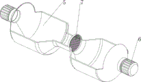
Fig. 1 is a schematic perspective view of a first embodiment of the present invention.
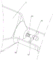
Fig. 2 is a schematic perspective view of a second embodiment of the present invention.
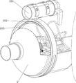
Fig. 3 is a schematic perspective view of a third embodiment of the present invention.
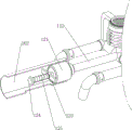
Fig. 4 is a schematic perspective view of the intake mechanism of the present invention.
Fig. 5 is a schematic perspective view of the plugging mechanism of the present invention.
Fig. 6 is a schematic perspective view of a first stirring mechanism of the present invention.
Fig. 7 is a schematic perspective view of a second stirring mechanism of the present invention.
Fig. 8 is a schematic perspective view of a third stirring mechanism of the present invention.
Fig. 9 is a schematic perspective view of the pushing mechanism of the present invention.
Fig. 10 is a schematic perspective view of the pressing mechanism of the present invention.
Fig. 11 is a schematic perspective view of the locking mechanism of the present invention.
Number designation in the figures: 1-support, 2-first support, 3-motor, 4-rotating rod, 5-storage box, 6-screw cap, 7-filter screen, 8-air inlet mechanism, 81-first air inlet pipe, 82-second support, 83-heater, 9-blocking mechanism, 91-third support, 92-hollow pipe, 93-conical block, 94-first spring, 10-stirring mechanism, 101-fourth support, 102-first hollow frame, 103-first magnet, 104-iron ball, 105-second magnet, 106-rotating seat, 107-stirring rod, 108-screw rod, 109-sliding rod, 1010-driving rod, 1011-second spring, 11-pushing mechanism, 111-fifth support, 112-second hollow frame, 113-a first sliding sleeve, 114-a first extrusion rod, 115-a third spring, 116-a pipeline, 12-a pressurizing mechanism, 121-a third hollow frame, 122-a second air inlet pipe, 123-a second sliding sleeve, 124-a second extrusion rod, 125-a fourth spring, 13-a clamping mechanism, 131-a third sliding sleeve, 132-a limiting block and 133-a concave block.
Detailed Description
The following further describes the technical solution with reference to specific embodiments, and it should be noted that: the words upper, lower, left, right, and the like used herein to indicate orientation are merely for the location of the illustrated structure in the corresponding figures. The serial numbers of the parts are themselves numbered herein, for example: first, second, etc. are used solely to distinguish one from another as to objects described herein, and do not have any sequential or technical meaning. The application states that: the connection and coupling, unless otherwise indicated, include both direct and indirect connections.
Example 1
The utility model provides a powder metallurgy is with drying device that has sorting function, as shown in fig. 1-3, including support 1, first support 2, motor 3, rotary rod 4, storage case 5, threaded cover 6, filter screen 7, admit air mechanism 8 and jam mechanism 9, 1 front side upper portion of support is equipped with first support 2, motor 3 is installed on 2 upper portions of first support, the rotary type is equipped with rotary rod 4 between the both sides around 1 upper portion of support, 4 front ends of rotary rod and the output shaft of motor 3, 4 middle parts of rotary rod are equipped with storage case 5, threaded cover 6 is installed to the equal threaded formula in the left and right sides of storage case 5, the middle part is equipped with filter screen 7 in the storage case 5, storage case 5 upper end middle part is equipped with admit air mechanism 8, the slidingtype middle part is equipped with jam mechanism 9 in the storage case 5.
When people need to dry and subpackage metallurgical powder, people can firstly screw off the left threaded cover 6 in a forward rotating mode, then people can pour the metallurgical powder into the left part of the storage box 5, after people pour the metallurgical powder into the left part of the storage box 5, people can reset the threaded cover 6 in a reverse rotating mode, then people can electrify the air inlet mechanism 8, after people adjust the air inlet mechanism 8, people can start the motor 3, the output shaft of the motor 3 rotates to drive the rotating rod 4 to rotate, and further drive the storage box 5 to rotate, when the left part of the storage box 5 rotates to the right upper part, the metallurgical powder can fall down onto the filter screen 7, and the metallurgical powder with smaller particles can fall down from the filter screen 7, when the left part of the storage box 5 rotates to the right upper part, the blocking mechanism 9 moves downwards, and when the blocking mechanism 9 moves downwards to be separated from the right part of the storage box 5, the less metal powder of granule alright drop to storage case 5 right part, when storage case 5 right part rotates to directly over, 5 right parts of storage case can be plugged up once more to jam mechanism 9, and then jam mechanism 9 can prevent the less metallurgical powder of granule from dropping downwards, thereby alright rotate through storage case 5 and carry out the partial shipment to metallurgical powder, rotate partial shipment in-process at storage case 5, the circular telegram mechanism 8 that admits air can let in steam to storage case 5, and then can dry metallurgical powder, accomplish the partial shipment after dry when metallurgical powder, people can close motor 3, after storage case 5 stall afterwards, people alright forward rotate and unscrew threaded cap 6, alright carry out the partial shipment to metallurgical powder afterwards, after metallurgical powder partial shipment is accomplished, people alright stop temporarily to admit air 8 circular telegrams of mechanism.
Example 2
In a preferred embodiment of the present invention, as shown in fig. 4 and 5, the air inlet mechanism 8 includes a first air inlet pipe 81, a second bracket 82 and a heater 83, the first air inlet pipe 81 is disposed in the middle of the upper end of the storage box 5, the second bracket 82 is disposed in the middle of the first air inlet pipe 81, the heater 83 is disposed in the middle of the upper portion of the second bracket 82, and the heater 83 is engaged with the first air inlet pipe 81.
When carrying out metallurgical powder partial shipment, people can be to heater 83 circular telegram, and then heater 83 alright to the gas heating in the first intake pipe 81, the gaseous accessible first intake pipe 81 after the heating flows to storage case 5 in afterwards, and then steam alright carry out the drying to the metallurgical powder in the storage case 5, and after metallurgical powder accomplished drying process, people alright temporarily stop to the heater 83 circular telegram.
The blocking mechanism 9 comprises a third support 91, a hollow pipe 92, a conical block 93 and a first spring 94, the third support 91 is arranged in the middle of the storage box 5, the hollow pipe 92 is arranged in the middle of the third support 91, the conical block 93 is arranged in the hollow pipe 92 in a sliding mode, the conical block 93 is matched with the right part of the storage box 5, the first spring 94 is sleeved on the left side of the conical block 93, and two ends of the first spring 94 are connected to the conical block 93 and the hollow pipe 92 respectively.
People are carrying out metallurgical powder partial shipment in-process, when storage case 5 left part rotates directly over, because toper piece 93 self weight reason, toper piece 93 can the downstream, first spring 94 is tensile, when toper piece 93 downstream to with storage case 5 right part separation, the less metallurgical powder of granule alright drop to storage case 5 right part, when storage case 5 right part rotates directly over, first spring 94 plays the reset role, and then can drive toper piece 93 and remove and reset, thereby toper piece 93 alright part of storage case is stopped up once more, and then alright prevent that the less metallurgical powder of granule from dropping back storage case 5 left part downwards, thereby alright carry out the partial shipment to metallurgical powder fast.
Example 3
In a preferred embodiment of the present invention, as shown in fig. 6-11, the stirring device 10 further comprises a stirring mechanism 10, the stirring mechanism 10 comprises a fourth support 101, a first hollow frame 102, a first magnet 103, an iron ball 104, a second magnet 105, a rotary seat 106, a stirring rod 107, a screw rod 108, a sliding rod 109, a lever 1010 and a second spring 1011, the fourth support 101 is disposed on both left and right sides of the upper end of the storage tank 5, the first hollow frame 102 is disposed on the fourth support 101, the first magnet 103 is slidably disposed inside the first hollow frame 102, the first magnet 103 is slidably engaged with the storage tank 5, the iron ball 104 is slidably disposed inside the first hollow frame 102, the iron ball 104 is engaged with the first magnet 103, the second magnet 105 is slidably disposed on both left and right sides of the storage tank 5, the second magnet 105 is engaged with the first magnet 103, the rotary seat 106 is disposed on both left and right sides of the storage tank 5, the rotary stirring rod 107 is disposed in the middle of both rotary seats 106, the outer sides of the two stirring rods 107 are connected with screw rods 108, the outer side of the rotating base 106 is provided with two sliding rods 109 at intervals, the second magnet 105 is connected with the two sliding rods 109 on the same side in a sliding manner, the middle parts of the rear sides of the two second magnets 105 are provided with shifting rods 1010, the shifting rods 1010 are matched with the screw rods 108 on the same side, a second spring 1011 is connected between the second magnet 105 and the sliding rods 109, and the second spring 1011 is wound on the sliding rods 109.
When people carry out the process of drying and subpackaging metallurgical powder, the storage box 5 rotates to drive the first hollow frame 102 to rotate, when the first hollow frame 102 rotates to the upper part, the iron ball 104 in the first hollow frame 102 slides downwards, when the iron ball 104 moves downwards to be contacted with the first magnet 103, the iron ball 104 extrudes the first magnet 103 downwards, and then drives the second magnet 105 to move downwards, the second spring 1011 is stretched, the second magnet 105 moves downwards to drive the shifting rod 1010 to move downwards, when the shifting rod 1010 moves downwards to be contacted with the screw rod 108, the shifting rod 1010 moves downwards along the grains of the screw rod 108, so as to drive the screw rod 108 to rotate, and then drive the stirring rod 107 to rotate, the stirring rod 107 can stir the metallurgical powder, when the first hollow frame 102 rotates to the lower part, the iron ball 104 in the first hollow frame 102 can slide and reset, when the iron ball 104 moves to be separated from the first magnet 103, second spring 1011 acts on that resets, and then can drive second magnet 105 and remove and reset, thereby can drive first magnet 103 and remove and reset, second magnet 105 removes and resets and can drive driving lever 1010 and remove and reset, driving lever 1010 removes along the line of hob 108, and then can drive the hob 108 reversal, thereby can drive the puddler 107 reversal, then alright again to metallurgical powder stirring, after metallurgical powder accomplishes dry partial shipment, storage case 5 stall alright make first hollow frame 102 rotate, and then alright make and stop stirring metallurgical powder temporarily.
The pushing mechanism 11 is further included, the pushing mechanism 11 includes a fifth support 111, a second hollow frame 112, a first sliding sleeve 113, a first extrusion rod 114, a third spring 115 and a pipeline 116, the fifth support 111 is arranged on the right portion of the inner wall of the first hollow frame 102 located on the left side, the second hollow frame 112 is arranged in the middle of the fifth support 111, the first sliding sleeve 113 is arranged in the middle of the outer wall of the second hollow frame 112, the first extrusion rod 114 is slidably arranged on the first sliding sleeve 113, the first extrusion rod 114 is slidably connected with the second hollow frame 112, the third spring 115 is sleeved on the first extrusion rod 114, two ends of the third spring 115 are respectively connected to the first sliding sleeve 113 and the first extrusion rod 114, the right side of the second hollow frame 112 is connected with the pipeline 116, and the lower end of the pipeline 116 is connected with the hollow pipe 92.
When the first hollow frame 102 positioned at the left side rotates to the upper side, the iron ball 104 in the first hollow frame 102 moves downwards to press the first magnet 103 to move downwards, when the first magnet 103 moves downward to contact the first pressing bar 114, the first magnet 103 presses the first pressing bar 114 downward, the third spring 115 is compressed, the first pressing bar 114 moves downward to press the air in the second hollow frame 112 downward, further, the pressure inside the hollow tube 92 can be increased to press the conical block 93 downwards, therefore, the conical block 93 can be prevented from being clamped with the hollow pipe 92, the efficiency of the metallurgical powder split charging is further influenced, when the first magnet 103 moves and resets, the third spring 115 resets, the first pressing rod 114 is driven to move and reset, so that the air in the hollow tube 92 can be pumped out through the pipeline 116, and the conical block 93 with reduced pressure in the hollow tube 92 can move and reset.
The air compressor further comprises a pressurizing mechanism 12, the pressurizing mechanism 12 comprises a third hollow frame 121, a second air inlet pipe 122, a second sliding sleeve 123, a second extrusion rod 124 and a fourth spring 125, the third hollow frame 121 is arranged on the left portion of the inner wall of the first hollow frame 102 on the right side, the second air inlet pipe 122 is connected to the left side of the third hollow frame 121, the left end of the second air inlet pipe 122 is connected to the middle portion of the first air inlet pipe 81, the second sliding sleeve 123 is arranged on the middle portion of the inner wall of the first hollow frame 102 on the right side, the second extrusion rod 124 is slidably arranged on the second sliding sleeve 123, the second extrusion rod 124 is slidably connected to the third hollow frame 121, the fourth spring 125 is sleeved on the second extrusion rod 124, and two ends of the fourth spring 125 are respectively connected to the second extrusion rod 124 and the second sliding sleeve 123.
When people rotate the first hollow frame 102 at the right side to the upper side in the process of introducing hot air for drying, the downward movement of the iron ball 104 in the first hollow frame 102 may press the first magnet 103 to move downward, when the first magnet 103 moves down to be in contact with the second pressing bar 124, the first magnet 103 may press the second pressing bar 124 downward, the fourth spring 125 is compressed, the second pressing bar 124 moves down to press the air inside the third hollow frame 121, and then the air can flow into the first air inlet pipe 81 through the second air inlet pipe 122, so that the air flow in the first air inlet pipe 81 can be accelerated, and then hot air can be quickly introduced for drying the metallurgical powder, when the first magnet 103 moves and resets, the fourth spring 125 resets, the second pressing rod 124 is driven to move and reset, so that the air pressing can be temporarily stopped, and the air flowing speed in the first air inlet pipe 81 can be slowed down again.
The clamping mechanism 13 is further included, the clamping mechanism 13 includes a third sliding sleeve 131, a limiting block 132 and a concave block 133, the third sliding sleeve 131 is arranged on the upper portion of the rear side of the support 1, the limiting block 132 is slidably arranged on the third sliding sleeve 131, the concave block 133 is connected to the rear end of the rotating rod 4, and the concave block 133 is matched with the limiting block 132.
After people need take out the metallurgical powder after the partial shipment drying process, people can rotate storage case 5, adjust storage case 5 to suitable position back when people, people can slide stopper 132 to the front side, slide to when blocking with spill piece 133 to the front side when stopper 132, rotary rod 4 alright temporary stop rotate, and then storage case 5 alright temporary stop rotate, when people need adjust the position to storage case 5 once more, people can pull stopper 132 to the rear side, when stopper 132 moves to when separating with spill piece 133 to the rear side, people alright rotate storage case 5 once more.
It should be understood that the above description is for exemplary purposes only and is not meant to limit the present invention. Those skilled in the art will appreciate that variations of the present invention are intended to be included within the scope of the claims herein.
Claims (8)
1. The utility model provides a powder metallurgy is with drying device who has sorting function which characterized in that, including:
the support comprises a support (1) and a first support (2), wherein the first support (2) is arranged at the upper part of the support (1);
the motor (3) is mounted on the upper portion of the first support (2);
the rotating rod (4) is rotatably arranged between two sides of the upper part of the support (1), and the rotating rod (4) is connected with an output shaft of the motor (3);
the middle part of the rotating rod (4) is provided with a storage box (5);
the threaded covers (6) are arranged on both sides of the storage box (5) in a threaded manner;
the filter screen (7) is arranged in the middle of the storage box (5);
the middle part of the upper end of the material storage box (5) is provided with an air inlet mechanism (8);
the middle part in the material storage box (5) is provided with a blocking mechanism (9) in a sliding way.
2. A drying apparatus with sorting function for powder metallurgy according to claim 1, wherein the air intake mechanism (8) comprises:
a first air inlet pipe (81), wherein the middle part of the upper end of the material storage box (5) is provided with the first air inlet pipe (81);
the middle part of the first air inlet pipe (81) is provided with a second bracket (82);
the heater (83), second support (82) upper portion centre is equipped with heater (83), and heater (83) and first intake pipe (81) cooperation.
3. A drying apparatus with sorting function for powder metallurgy according to claim 2, wherein the clogging means (9) comprises:
a third bracket (91), wherein the middle part in the storage box (5) is provided with the third bracket (91);
the middle part of the third bracket (91) is provided with a hollow pipe (92);
the hollow pipe (92) is internally provided with a conical block (93) in a sliding manner, and the conical block (93) is matched with the material storage box (5);
the first spring (94) is sleeved on the conical block (93), and two ends of the first spring (94) are respectively connected to the conical block (93) and the hollow pipe (92).
4. The drying apparatus with a sorting function for powder metallurgy according to claim 3, further comprising a stirring mechanism (10), wherein the stirring mechanism (10) comprises:
the fourth supports (101) are arranged at the two upper ends of the material storage box (5);
the fourth bracket (101) is provided with a first hollow frame (102);
the first magnet (103) is arranged inside the first hollow frame (102) in a sliding mode, and the first magnet (103) is in sliding fit with the material storage box (5);
the iron ball (104) is arranged in the first hollow frame (102) in a sliding mode, and the iron ball (104) is matched with the first magnet (103);
the second magnet (105) is arranged in the storage box (5) in a sliding manner, and the second magnet (105) is matched with the first magnet (103);
the rotary seat (106) is arranged at two parts in the storage box (5);
the middle parts of the two rotating seats (106) are respectively and rotatably provided with a stirring rod (107);
the outer sides of the two stirring rods (107) are connected with the screw rods (108);
the outer side of the rotating seat (106) is provided with two sliding rods (109) at intervals, and the second magnet (105) is connected with the two sliding rods (109) positioned on the same side in a sliding manner;
the middle parts of the two second magnets (105) are respectively provided with a deflector rod (1010), and the deflector rods (1010) are matched with the screw rods (108) positioned on the same side;
and a second spring (1011), wherein the second spring (1011) is connected between the second magnet (105) and the slide rod (109), and the second spring (1011) is wound on the slide rod (109).
5. The drying apparatus with a sorting function for powder metallurgy according to claim 4, further comprising a pushing mechanism (11), wherein the pushing mechanism (11) comprises:
the fifth bracket (111), the inner wall of the first hollow frame (102) positioned at the outer side is provided with the fifth bracket (111);
the middle part of the fifth bracket (111) is provided with a second hollow frame (112);
the middle part of the outer wall of the second hollow frame (112) is provided with a first sliding sleeve (113);
the first extrusion rod (114) is arranged on the first sliding sleeve (113) in a sliding mode, and the first extrusion rod (114) is connected with the second hollow frame (112) in a sliding mode;
the third spring (115) is sleeved on the first extrusion rod (114), and two ends of the third spring (115) are respectively connected to the first sliding sleeve (113) and the first extrusion rod (114);
the pipeline (116) is connected to the second hollow frame (112), and the lower end of the pipeline (116) is connected with the hollow pipe (92).
6. The drying apparatus with a classifying function for powder metallurgy according to claim 5, further comprising a pressing mechanism (12), wherein the pressing mechanism (12) comprises:
the inner wall of the first hollow frame (102) positioned at the inner side is provided with a third hollow frame (121);
the third hollow frame (121) is connected with a second air inlet pipe (122), and the second air inlet pipe (122) is connected with the middle part of the first air inlet pipe (81);
the second sliding sleeve (123), the middle part of the inner wall of the first hollow frame (102) positioned at the inner side is provided with the second sliding sleeve (123);
the second extrusion rod (124) is arranged on the second sliding sleeve (123) in a sliding mode, and the second extrusion rod (124) is connected with the third hollow frame (121) in a sliding mode;
and the second extrusion rod (124) is sleeved with a fourth spring (125), and two ends of the fourth spring (125) are respectively connected to the second extrusion rod (124) and the second sliding sleeve (123).
7. The drying device with a sorting function for powder metallurgy according to claim 6, characterized in that the drying device further comprises a blocking mechanism (13), wherein the blocking mechanism (13) comprises:
the upper part of the support (1) is provided with a third sliding sleeve (131);
the limiting block (132), the third sliding sleeve (131) is provided with the limiting block (132) in a sliding manner;
the concave block (133), the rotary rod (4) is connected with the concave block (133), and the concave block (133) is matched with the limiting block (132).
8. The drying apparatus having a sorting function for powder metallurgy according to claim 7, wherein: the concave block (133) is evenly provided with a groove matched with the limit block (132).
Priority Applications (1)
| Application Number | Priority Date | Filing Date | Title |
|---|---|---|---|
| CN202111496779.7A CN114353464B (en) | 2021-12-09 | 2021-12-09 | Drying device with sorting function for powder metallurgy |
Applications Claiming Priority (1)
| Application Number | Priority Date | Filing Date | Title |
|---|---|---|---|
| CN202111496779.7A CN114353464B (en) | 2021-12-09 | 2021-12-09 | Drying device with sorting function for powder metallurgy |
Publications (2)
| Publication Number | Publication Date |
|---|---|
| CN114353464A true CN114353464A (en) | 2022-04-15 |
| CN114353464B CN114353464B (en) | 2023-09-05 |
Family
ID=81097824
Family Applications (1)
| Application Number | Title | Priority Date | Filing Date |
|---|---|---|---|
| CN202111496779.7A Active CN114353464B (en) | 2021-12-09 | 2021-12-09 | Drying device with sorting function for powder metallurgy |
Country Status (1)
| Country | Link |
|---|---|
| CN (1) | CN114353464B (en) |
Cited By (2)
| Publication number | Priority date | Publication date | Assignee | Title |
|---|---|---|---|---|
| CN114633960A (en) * | 2022-05-23 | 2022-06-17 | 西安宝德九土新材料有限公司 | Metal powder processing apparatus is used in metallurgical production of big height-diameter ratio tungsten alloy powder |
| CN114850479A (en) * | 2022-05-20 | 2022-08-05 | 罗万里 | Uniform-speed rotating blanking device for continuous hydrogen crushing |
Citations (10)
| Publication number | Priority date | Publication date | Assignee | Title |
|---|---|---|---|---|
| CH663462A5 (en) * | 1984-11-07 | 1987-12-15 | Italvacuum Snc | ROTARY DRYER FOR PARTICULAR SOLIDS. |
| JPH0889902A (en) * | 1994-09-20 | 1996-04-09 | Kawasaki Heavy Ind Ltd | Classifier |
| CN107377362A (en) * | 2017-05-08 | 2017-11-24 | 六安市富民农用器材制造有限公司 | A kind of Chinese medicine high frequency zone drying unit |
| CN109945608A (en) * | 2019-03-26 | 2019-06-28 | 江苏金山啤酒原料有限公司 | A kind of novel energy-conserving malt drying device |
| CN110906711A (en) * | 2019-12-06 | 2020-03-24 | 洪瑞茜 | Drying device is used in processing of drum-type dendrobii officmalis caulis |
| CN210663704U (en) * | 2019-10-25 | 2020-06-02 | 湖北优世达科技股份有限公司 | Rotary vacuum drying machine for producing perfluoroalkyl xanthyl fluoride derivatives |
| CN212596906U (en) * | 2020-03-17 | 2021-02-26 | 鲁伟芳 | Material screening device |
| CN113071722A (en) * | 2021-05-19 | 2021-07-06 | 江西淳迪生物科技有限公司 | Quantitative medicine powder split charging equipment |
| CN113117568A (en) * | 2021-04-12 | 2021-07-16 | 南城县晨风香料有限公司 | Pure vegetable oil pesticide solvent processing extraction element |
| CN113305009A (en) * | 2021-06-15 | 2021-08-27 | 葛强 | Sealed rolling type multi-stage screening machine |
-
2021
- 2021-12-09 CN CN202111496779.7A patent/CN114353464B/en active Active
Patent Citations (10)
| Publication number | Priority date | Publication date | Assignee | Title |
|---|---|---|---|---|
| CH663462A5 (en) * | 1984-11-07 | 1987-12-15 | Italvacuum Snc | ROTARY DRYER FOR PARTICULAR SOLIDS. |
| JPH0889902A (en) * | 1994-09-20 | 1996-04-09 | Kawasaki Heavy Ind Ltd | Classifier |
| CN107377362A (en) * | 2017-05-08 | 2017-11-24 | 六安市富民农用器材制造有限公司 | A kind of Chinese medicine high frequency zone drying unit |
| CN109945608A (en) * | 2019-03-26 | 2019-06-28 | 江苏金山啤酒原料有限公司 | A kind of novel energy-conserving malt drying device |
| CN210663704U (en) * | 2019-10-25 | 2020-06-02 | 湖北优世达科技股份有限公司 | Rotary vacuum drying machine for producing perfluoroalkyl xanthyl fluoride derivatives |
| CN110906711A (en) * | 2019-12-06 | 2020-03-24 | 洪瑞茜 | Drying device is used in processing of drum-type dendrobii officmalis caulis |
| CN212596906U (en) * | 2020-03-17 | 2021-02-26 | 鲁伟芳 | Material screening device |
| CN113117568A (en) * | 2021-04-12 | 2021-07-16 | 南城县晨风香料有限公司 | Pure vegetable oil pesticide solvent processing extraction element |
| CN113071722A (en) * | 2021-05-19 | 2021-07-06 | 江西淳迪生物科技有限公司 | Quantitative medicine powder split charging equipment |
| CN113305009A (en) * | 2021-06-15 | 2021-08-27 | 葛强 | Sealed rolling type multi-stage screening machine |
Cited By (2)
| Publication number | Priority date | Publication date | Assignee | Title |
|---|---|---|---|---|
| CN114850479A (en) * | 2022-05-20 | 2022-08-05 | 罗万里 | Uniform-speed rotating blanking device for continuous hydrogen crushing |
| CN114633960A (en) * | 2022-05-23 | 2022-06-17 | 西安宝德九土新材料有限公司 | Metal powder processing apparatus is used in metallurgical production of big height-diameter ratio tungsten alloy powder |
Also Published As
| Publication number | Publication date |
|---|---|
| CN114353464B (en) | 2023-09-05 |
Similar Documents
| Publication | Publication Date | Title |
|---|---|---|
| CN114353464A (en) | Drying device with sorting function for powder metallurgy | |
| US7927388B2 (en) | Apparatus and method for producing woodfuel briquettes, pellets, compounds, agglomerates, granulates, and the like | |
| CN110679303A (en) | Straw processing equipment | |
| CN208406415U (en) | A kind of hopper with dust-extraction unit | |
| CN108380137A (en) | A kind of multi-functional pellet granulator | |
| CN109092416B (en) | Water paint grinds blendor | |
| CN211412699U (en) | Zinc stearate produces filter equipment | |
| CN117181379A (en) | Grinding device is smashed to graphite production raw materials | |
| CN112371498B (en) | Screening equipment for processing granular materials | |
| CN208494985U (en) | A kind of new-type carbon black air classifier | |
| CN213825251U (en) | Chinese-medicinal material is with smashing grinder | |
| CN209255172U (en) | Rotation screen device for gypsum powder production line | |
| CN213286979U (en) | High-efficient and few capsule raw materials reducing mechanism who prevents blocking up | |
| CN208287961U (en) | A kind of multi-functional pellet granulator | |
| CN113426198A (en) | Dewatering device for mine beneficiation | |
| CN209333931U (en) | A kind of medicine preparation pulverizer improvement mechanism | |
| CN203400855U (en) | Reverse flow type vibration cooling screen for clean area | |
| CN117244621B (en) | Fine powder crushing device and process for iron ore | |
| CN220464715U (en) | Film blowing machine | |
| CN214842150U (en) | Medicine rapid draing device | |
| CN219309351U (en) | Dustproof fine screening device used in lime processing process | |
| CN218359871U (en) | Crusher for puffed feed | |
| CN208727603U (en) | A kind of nanometer calcium carbonate grinding powder concentrator | |
| CN219804985U (en) | Drug particle screening device | |
| CN219051993U (en) | Raw material screening device for rice storage |
Legal Events
| Date | Code | Title | Description |
|---|---|---|---|
| PB01 | Publication | ||
| PB01 | Publication | ||
| SE01 | Entry into force of request for substantive examination | ||
| SE01 | Entry into force of request for substantive examination | ||
| TA01 | Transfer of patent application right |
Effective date of registration: 20230809 Address after: 423000 Hi-tech Industrial Park, Yongxing County Economic Development Zone, Chenzhou City, Hunan Province Applicant after: Yongxing Yindu Rare and Precious Metals Research Institute Co.,Ltd. Address before: 518109 room 108, building 9, No. 7, Langkou Industrial Park, Langkou community, Dalang street, Longhua District, Guangzhou City, Guangdong Province Applicant before: Hu Yangqi |
|
| TA01 | Transfer of patent application right | ||
| GR01 | Patent grant | ||
| GR01 | Patent grant |