CN114352645B - Preparation method of annular retainer ring for shaft for gear shaft - Google Patents
Preparation method of annular retainer ring for shaft for gear shaft Download PDFInfo
- Publication number
- CN114352645B CN114352645B CN202210266452.9A CN202210266452A CN114352645B CN 114352645 B CN114352645 B CN 114352645B CN 202210266452 A CN202210266452 A CN 202210266452A CN 114352645 B CN114352645 B CN 114352645B
- Authority
- CN
- China
- Prior art keywords
- shaft
- retainer ring
- annular
- annular retainer
- clamping groove
- Prior art date
- Legal status (The legal status is an assumption and is not a legal conclusion. Google has not performed a legal analysis and makes no representation as to the accuracy of the status listed.)
- Active
Links
Images


Classifications
-
- F—MECHANICAL ENGINEERING; LIGHTING; HEATING; WEAPONS; BLASTING
- F16—ENGINEERING ELEMENTS AND UNITS; GENERAL MEASURES FOR PRODUCING AND MAINTAINING EFFECTIVE FUNCTIONING OF MACHINES OR INSTALLATIONS; THERMAL INSULATION IN GENERAL
- F16C—SHAFTS; FLEXIBLE SHAFTS; ELEMENTS OR CRANKSHAFT MECHANISMS; ROTARY BODIES OTHER THAN GEARING ELEMENTS; BEARINGS
- F16C35/00—Rigid support of bearing units; Housings, e.g. caps, covers
- F16C35/04—Rigid support of bearing units; Housings, e.g. caps, covers in the case of ball or roller bearings
- F16C35/06—Mounting or dismounting of ball or roller bearings; Fixing them onto shaft or in housing
- F16C35/063—Fixing them on the shaft
-
- F—MECHANICAL ENGINEERING; LIGHTING; HEATING; WEAPONS; BLASTING
- F16—ENGINEERING ELEMENTS AND UNITS; GENERAL MEASURES FOR PRODUCING AND MAINTAINING EFFECTIVE FUNCTIONING OF MACHINES OR INSTALLATIONS; THERMAL INSULATION IN GENERAL
- F16C—SHAFTS; FLEXIBLE SHAFTS; ELEMENTS OR CRANKSHAFT MECHANISMS; ROTARY BODIES OTHER THAN GEARING ELEMENTS; BEARINGS
- F16C2326/00—Articles relating to transporting
- F16C2326/20—Land vehicles
- F16C2326/24—Steering systems, e.g. steering rods or columns
Landscapes
- Engineering & Computer Science (AREA)
- General Engineering & Computer Science (AREA)
- Mechanical Engineering (AREA)
- Power Steering Mechanism (AREA)
Abstract
The invention discloses a preparation method of an annular retainer ring for a shaft, which mainly comprises two key points, wherein the shape of the annular retainer ring for the shaft is annular, and the internal shape and the size of the annular retainer ring for the shaft are designed according to the shape and the size of the section of a helical gear shaft, so that the annular retainer ring for the shaft can move up and down along the tooth grooves of the helical gear shaft; calculating the thrust to be born by the annular retainer ring for the shaft according to the use requirement, calculating the required stress area A1 after the annular retainer ring for the shaft is matched with the clamping groove according to theory, selecting the material and the thickness of the annular retainer ring for the shaft firstly during design, then selecting the dimensions of the outer diameter d1 of the clamping groove of the helical gear shaft and the working inner diameter d2 of the annular retainer ring for the shaft, and calculating the stress area A2 of the annular retainer ring for the shaft matched with the clamping groove, wherein A2 is required to be more than 3 times of A1.
Description
Technical Field
The invention relates to the technical field of automobile steering systems, in particular to a preparation method of an annular retainer ring for a shaft for a gear shaft.
Background
The rack-and-pinion type mechanical steering gear is mainly used for cars and light mini-cars, is the most important part for realizing the steering function of automobiles, and is also an important part for the running safety of the automobiles. One important component of a rack and pinion type mechanical steering gear is a helical gear subassembly.
The elastic retainer ring for the existing standard shaft is the main reason for the insufficiency of the performance and the service life of the spiral gear sub-assembly, and the existing spiral gear sub-assembly is analyzed, and the main factors influencing the performance and the service life of the spiral gear sub-assembly and not meeting the requirements are found as follows: a: the existing elastic retainer ring for the shaft is provided with an opening which is not a full circle, and the opening is easy to open and fall off due to uneven stress when the elastic retainer ring is subjected to impact load; b: the clamping groove processed by the spiral gear shaft at the gear tooth part is not a full circle, so that the blocking area of the clamping groove is influenced; c: the opening of the existing elastic check ring for the shaft needs to be opened by clamp ring pliers, the inner diameter can be clamped in only after being enlarged, the opening is limited by the performance of the material, the opening degree is within the elastic deformation range of the material and cannot be too large, the increase of the inner diameter is limited, and therefore the clamping depth of the elastic check ring for the shaft in the clamping groove is small, and the elastic check ring for the shaft is easy to deform, break and fall off when being subjected to impact load.
As shown in fig. 1, this is a structure currently in use, and its structure composition is: the first helical gear shaft 101 is press-fitted with a bearing 102, and the bearing 102 is blocked by a shaft circlip 103 which is clamped in a first clamping groove 104 of the first helical gear shaft 101. There are three factors that limit the use of this structure: a: the first helical gear shaft 101 has an inherent characteristic that the first helical gear shaft 101 generates an axial bidirectional thrust when rotating forward and backward, the thrust is generated by impact of different degrees due to uneven running road surface, an impact force in one direction is transmitted to the bearing 102 through the first clamping groove 104 on the first helical gear shaft 101 and the shaft circlip 103, so that the first clamping groove 104 on the first helical gear shaft 101 and the shaft circlip 103 bear the impact force, the proportion of the impact force is related to the gear pressure angle of the first helical gear shaft 101, 500Kg is taken according to the rack thrust of a common mechanical steering gear, the theoretical calculation of the axial thrust on the first helical gear shaft 101 can reach 200Kg, and the stress area of the first clamping groove 104 matched with the shaft circlip 103 can meet the requirement until 7mm is reached; b: because the structure of the existing shaft circlip 103 is not a complete circle due to the installation process requirements, an opening 105 is required, the shaft circlip 103 for installation needs to be opened to be installed, the opening amount is not too large, and the first clamping groove 104 matched with the opening is not too deep; c: in the structure shown in fig. 1, the shaft circlip 103 is clamped in the gear tooth section of the first helical gear shaft 101, the first locking groove 104 is not a complete circle, if the notch of the shaft circlip 103 falls on the tooth back of the first locking groove 104, there is one less stress point, and the effect of blocking the bearing 102 is worse. The first helical gear shaft 101 subassembly designed and manufactured according to the above scheme has the force-bearing area of the first clamping groove 104 matched with the retainer ring reaching 6.6mm, and the mechanical steering gear manufactured by using the structure has failure due to the fact that the shaft elastic retainer ring 103 deforms and breaks and the first helical gear shaft 101 moves up and down when about 10% of life test is completed. If the annular retainer ring is used in a real vehicle, serious potential safety hazards are brought to the driving of the vehicle, and therefore the method for preparing the annular retainer ring for the shaft for the gear shaft is provided.
Disclosure of Invention
In order to solve the technical problems, the invention provides the following technical scheme: a method for preparing an annular retainer ring for a shaft for a gear shaft comprises the following steps:
s1: drawing a partial section shape graph of the gear teeth according to gear parameters (the number of teeth is 5, the normal modulus is 2.1167 and the normal pressure angle is 20 degrees) for a second helical gear shaft with the number of teeth being 5;
s2: according to the use requirement, the shaft annular retainer ring bears 200 kilograms of thrust, the material of the shaft annular retainer ring is 65Mn and the thickness of the shaft annular retainer ring is 1.3mm, the stress area of the second clamping groove matched with the shaft annular retainer ring is calculated to be 7mm according to theory, the outer diameter d1 of the second clamping groove on the second helical gear shaft is selected to be 16.8mm and the working inner diameter d2 of the shaft annular retainer ring is selected to be 17mm during design, and the stress area of the second clamping groove matched with the shaft annular retainer ring is measured and calculated to be 26.3mm, which is larger than 3 times of the theoretical calculation;
s3: designing the internal shape of the annular retainer ring for the shaft, and designing the angle and the size of the clamping guide to ensure that the annular retainer ring for the shaft can be sleeved on the second helical gear shaft and can smoothly slide down along the tooth grooves;
s4: designing the shapes and the sizes of two protruding points for preventing the shaft from passing and stopping the shaft annular check ring, ensuring that the shaft annular check ring can be clamped when rotating clockwise after being arranged in a second clamping groove on a second helical gear shaft, and can be withdrawn only when reaching the designed withdrawal torque when rotating anticlockwise;
s5: determining the final section of a second clamping groove on a second helical gear shaft;
s6: in order to facilitate installation and disassembly, a small clamping groove on the excircle of the annular retaining ring for the shaft is added, and the final section of the annular retaining ring for the shaft is determined.
As a preferred technical scheme of the invention, after the shaft is made of the annular retainer ring, the bearing is pressed on the second helical gear shaft, and the shaft annular retainer ring is clamped in the second clamping groove of the second helical gear shaft to block the bearing.
Compared with the prior art, the invention can achieve the following beneficial effects:
1. the bearing and the annular retainer ring for the shaft are installed on a second helical gear shaft to form a second helical gear shaft sub-assembly, then the second helical gear shaft sub-assembly is installed in a corresponding mechanical steering gear to carry out a life test, abnormal sound and up-and-down movement of the second helical gear shaft are not found in the life test, a product is disassembled for analysis after the requirement of the life test is met, deformation and cracks of the annular retainer ring for the shaft are not found, the continuous test is well assembled again, the product is disassembled for analysis after the requirement of 50% of the life test is exceeded, and the deformation and the cracks of the annular retainer ring for the shaft are not found. The existing spiral gear shaft sub-assembly made of the elastic check ring for the shaft standard cannot solve the problem that the elastic check ring for the shaft is open, the depth of a clamping groove cannot be deepened, so that the stress area of the check ring is increased, the spiral gear shaft sub-assembly is tested when the spiral gear shaft sub-assembly is installed in a same mechanical steering gear, and the spiral gear shaft fails due to vertical movement of the elastic check ring when about 10% of service life test is completed.
Drawings
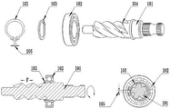
FIG. 1 is a schematic view of a first helical gear sub-assembly of the prior art;
FIG. 2 is a schematic view showing a design process of a manufacturing method of an annular retainer ring for a shaft for a second helical gear shaft according to the present invention;
FIG. 3 is a schematic structural view of a second helical gear sub-assembly of the present invention;
wherein: 101. a first helical gear shaft; 102. a bearing; 103. a circlip for the shaft; 104. a first card slot; 105. an opening; 201. a second helical gear shaft; 202. a second card slot; 203. the shaft is provided with an annular retainer ring.
Detailed Description
The present invention will be further described with reference to specific embodiments for the purpose of facilitating an understanding of technical means, characteristics of creation, objectives and functions realized by the present invention, but the following embodiments are only preferred embodiments of the present invention, and are not intended to be exhaustive. Based on the embodiments in the implementation, other embodiments obtained by those skilled in the art without any creative efforts belong to the protection scope of the present invention. The experimental methods in the following examples are conventional methods unless otherwise specified, and materials, reagents and the like used in the following examples are commercially available unless otherwise specified.
Example (b):
as shown in fig. 2, a method for preparing an annular retainer ring for a shaft for a gear shaft includes the following steps:
s1: drawing a partial section shape diagram of the gear teeth according to gear parameters (the number of teeth is 5, the normal modulus is 2.1167, and the normal pressure angle is 20 degrees) for a second helical gear shaft 201 with the number of teeth being 5;
s2: according to the use requirement, the shaft annular retainer ring 203 is required to bear 200kg of thrust, the material of the shaft annular retainer ring 203 is 65Mn and the thickness is 1.3mm, the stress area of the second clamping groove 202 matched with the shaft annular retainer ring 203 is theoretically calculated to be 7mm, the outer diameter d1 of the second clamping groove 202 on the second helical gear shaft 201 is selected to be 16.8mm and the working inner diameter d2 of the shaft annular retainer ring 203 is selected to be 17mm, and the stress area of the second clamping groove 202 matched with the shaft annular retainer ring 203 is calculated to be 26.3mm, which is more than 3 times of the theoretical calculation;
s3: designing the internal shape of the annular retaining ring 203 for the shaft, and designing the angle and the size of the clamping guide to ensure that the annular retaining ring 203 for the shaft can be sleeved on the second helical gear shaft 201 and can smoothly slide down along the tooth grooves;
s4: designing the shapes and the sizes of two protruding points for preventing and stopping the shaft annular retainer ring 203, ensuring that the shaft annular retainer ring 203 can be clamped when rotating clockwise after being arranged on a second clamping groove 202 on a second helical gear shaft 201, and can be withdrawn only when reaching the designed withdrawal torque when rotating anticlockwise;
s5: determining a final cross section of the second clamping groove 202 on the second helical gear shaft 201;
s6: in order to facilitate mounting and dismounting, a small clamping groove on the outer circle of the annular retaining ring 203 for the shaft is added, and the final section of the annular retaining ring 203 for the shaft is determined.
As shown in fig. 3, after the annular retainer ring 203 for a shaft is manufactured, the bearing 102 is press-fitted on the second helical gear shaft 201, and the annular retainer ring 203 for a shaft is engaged with the second engaging groove 202 of the second helical gear shaft 201 to retain the bearing 102.
A: the annular retainer ring 203 for the shaft for the second helical gear shaft 201 is designed into an annular shape, so that the stress area of the annular retainer ring clamped into the second clamping groove 202 is circularly symmetrical, and when the annular retainer ring 203 for the shaft is subjected to impact load, the stress in the circumferential direction is uniform, and the circumferential direction is not easily damaged; b: the design of increasing the stress area of the second card slot 202 should ensure that the stress area of the second card slot 202 is 3 times larger than the stress area of the second card slot 202 calculated according to theory; c: the inner shape of the annular collar 203 for the second helical gear shaft 201 is designed according to the cross-sectional shape of the second helical gear shaft 201, and the arc length of the clamped part is increased as much as possible under the condition that the annular collar 203 for the shaft can slide up and down on the second helical gear shaft 201 along the tooth grooves; d: an annular collar 203 for a shaft for designing the second helical gear shaft 201 is clamped in the second clamping groove 202 to guide, prevent and stop two salient points; e: for convenient installation and disassembly, a small clamping groove can be designed on the excircle of the annular retainer ring 203 for the shaft, and the hook wrench can be used for installation and disassembly.
In the present invention, unless otherwise expressly stated or limited, "above" or "below" a first feature means that the first and second features are in direct contact, or that the first and second features are not in direct contact but are in contact with each other via another feature therebetween. Also, the first feature being "on," "above" and "over" the second feature includes the first feature being directly on and obliquely above the second feature, or merely indicating that the first feature is at a higher level than the second feature. A first feature being "under," "below," and "beneath" a second feature includes the first feature being directly under and obliquely below the second feature, or simply meaning that the first feature is at a lesser elevation than the second feature.
The foregoing shows and describes the general principles, essential features, and advantages of the invention. It will be understood by those skilled in the art that the present invention is not limited to the embodiments described above, and the preferred embodiments of the present invention are described in the above embodiments and the description, and are not intended to limit the present invention. The scope of the invention is defined by the appended claims and equivalents thereof.
Claims (2)
1. A method for preparing an annular retainer ring for a shaft for a gear shaft is characterized by comprising the following steps of:
s1: drawing a partial section shape diagram of the gear teeth according to the gear parameters of 5 teeth, 2.1167 normal modulus and 20 degrees normal pressure angle for a second helical gear shaft (201) with 5 teeth;
s2: according to the using requirements, the annular retaining ring (203) for the shaft is required to bear 200 kilograms of thrust, the material of the annular retaining ring (203) for the shaft is selected to be 65Mn and the thickness of the annular retaining ring (203) for the shaft is 1.3mm, the stress area of the annular retaining ring (203) for the shaft matched with the second clamping groove (202) is calculated to be 7mm according to theory, the outer diameter d1 of the second clamping groove (202) on the second helical gear shaft (201) is selected to be 16.8mm and the working inner diameter d2 of the annular retaining ring (203) for the shaft is calculated to be 17mm, and the stress area of the second clamping groove (202) matched with the annular retaining ring (203) for the shaft is calculated to be 26.3mm which is more than 3 times of the theoretical calculation;
s3: designing the internal shape of the annular retainer ring (203) for the shaft, and designing the angle and the size of the clamping guide to ensure that the annular retainer ring (203) for the shaft can be sleeved on the second helical gear shaft (201) and can smoothly slide down along the tooth grooves;
s4: designing the shapes and the sizes of two salient points for preventing and stopping the shaft annular check ring (203), ensuring that the shaft annular check ring (203) can be clamped when rotating clockwise after being arranged on a second clamping groove (202) on a second helical gear shaft (201), and can be withdrawn only when reaching the designed withdrawal torque when rotating anticlockwise;
s5: determining a final section of a second clamping groove (202) on a second helical gear shaft (201);
s6: in order to facilitate mounting and dismounting, a small clamping groove on the excircle of the annular retaining ring (203) for the shaft is added, and the final section of the annular retaining ring (203) for the shaft is determined.
2. The method for manufacturing an annular retainer ring for a shaft for a gear shaft according to claim 1, wherein: after the shaft is made of the annular retainer ring (203), the bearing (102) is pressed on the second spiral gear shaft (201), and the bearing (102) is blocked in the second clamping groove (202) of the second spiral gear shaft (201) by the annular retainer ring (203) for the shaft in a clamping mode.
Priority Applications (1)
| Application Number | Priority Date | Filing Date | Title |
|---|---|---|---|
| CN202210266452.9A CN114352645B (en) | 2022-03-18 | 2022-03-18 | Preparation method of annular retainer ring for shaft for gear shaft |
Applications Claiming Priority (1)
| Application Number | Priority Date | Filing Date | Title |
|---|---|---|---|
| CN202210266452.9A CN114352645B (en) | 2022-03-18 | 2022-03-18 | Preparation method of annular retainer ring for shaft for gear shaft |
Publications (2)
| Publication Number | Publication Date |
|---|---|
| CN114352645A CN114352645A (en) | 2022-04-15 |
| CN114352645B true CN114352645B (en) | 2022-05-27 |
Family
ID=81094325
Family Applications (1)
| Application Number | Title | Priority Date | Filing Date |
|---|---|---|---|
| CN202210266452.9A Active CN114352645B (en) | 2022-03-18 | 2022-03-18 | Preparation method of annular retainer ring for shaft for gear shaft |
Country Status (1)
| Country | Link |
|---|---|
| CN (1) | CN114352645B (en) |
Citations (12)
| Publication number | Priority date | Publication date | Assignee | Title |
|---|---|---|---|---|
| FR1068200A (en) * | 1952-12-05 | 1954-06-23 | Le Fermoir Francais | Clasp manufacturing process |
| JPS5890342A (en) * | 1981-11-24 | 1983-05-30 | Morioka Sangyo Kk | Working method for groove for snap ring of pin and flat die for working |
| JPH0217223A (en) * | 1988-07-04 | 1990-01-22 | F C C:Kk | Manufacture of block ring for synchronous intermeshing speed change gear |
| WO2006114854A1 (en) * | 2005-04-12 | 2006-11-02 | Nippon Seimitsu Denshi Co., Ltd. | Retainer ring for cmp device, method of manufacturing the same, and cmp device |
| CN101122309A (en) * | 2007-07-03 | 2008-02-13 | 洛阳世必爱特种轴承有限公司 | Circlip for cylindrical roller bearing and its production method |
| CN101508024A (en) * | 2009-03-13 | 2009-08-19 | 洛阳轴研科技股份有限公司 | Processing method of split retainer |
| CN102274905A (en) * | 2011-03-21 | 2011-12-14 | 杭州钱江弹簧有限公司 | Technology for processing retainer ring of turbosupercharger |
| CN202804677U (en) * | 2012-07-20 | 2013-03-20 | 秦皇岛兴龙轮毂有限公司 | Adjustable radial positioning ring for machining hubs |
| CN103464973A (en) * | 2013-09-02 | 2013-12-25 | 重庆材料研究院有限公司 | Production method of Fe-Cr-Ni-based high temperature alloy high-strength spiral elastic retainer ring |
| JP2015037142A (en) * | 2013-08-14 | 2015-02-23 | シーエヌユーエス カンパニー,リミテッド | Retainer ring structure for chemical mechanical polisher, and manufacturing method thereof |
| CN106583592A (en) * | 2016-12-28 | 2017-04-26 | 西安西工大超晶科技发展有限责任公司 | Preparation method of high-elasticity spiral retainer ring |
| CN112846004A (en) * | 2021-03-17 | 2021-05-28 | 中国航发动力股份有限公司 | Method and tool for processing elastic retainer ring |
-
2022
- 2022-03-18 CN CN202210266452.9A patent/CN114352645B/en active Active
Patent Citations (12)
| Publication number | Priority date | Publication date | Assignee | Title |
|---|---|---|---|---|
| FR1068200A (en) * | 1952-12-05 | 1954-06-23 | Le Fermoir Francais | Clasp manufacturing process |
| JPS5890342A (en) * | 1981-11-24 | 1983-05-30 | Morioka Sangyo Kk | Working method for groove for snap ring of pin and flat die for working |
| JPH0217223A (en) * | 1988-07-04 | 1990-01-22 | F C C:Kk | Manufacture of block ring for synchronous intermeshing speed change gear |
| WO2006114854A1 (en) * | 2005-04-12 | 2006-11-02 | Nippon Seimitsu Denshi Co., Ltd. | Retainer ring for cmp device, method of manufacturing the same, and cmp device |
| CN101122309A (en) * | 2007-07-03 | 2008-02-13 | 洛阳世必爱特种轴承有限公司 | Circlip for cylindrical roller bearing and its production method |
| CN101508024A (en) * | 2009-03-13 | 2009-08-19 | 洛阳轴研科技股份有限公司 | Processing method of split retainer |
| CN102274905A (en) * | 2011-03-21 | 2011-12-14 | 杭州钱江弹簧有限公司 | Technology for processing retainer ring of turbosupercharger |
| CN202804677U (en) * | 2012-07-20 | 2013-03-20 | 秦皇岛兴龙轮毂有限公司 | Adjustable radial positioning ring for machining hubs |
| JP2015037142A (en) * | 2013-08-14 | 2015-02-23 | シーエヌユーエス カンパニー,リミテッド | Retainer ring structure for chemical mechanical polisher, and manufacturing method thereof |
| CN103464973A (en) * | 2013-09-02 | 2013-12-25 | 重庆材料研究院有限公司 | Production method of Fe-Cr-Ni-based high temperature alloy high-strength spiral elastic retainer ring |
| CN106583592A (en) * | 2016-12-28 | 2017-04-26 | 西安西工大超晶科技发展有限责任公司 | Preparation method of high-elasticity spiral retainer ring |
| CN112846004A (en) * | 2021-03-17 | 2021-05-28 | 中国航发动力股份有限公司 | Method and tool for processing elastic retainer ring |
Also Published As
| Publication number | Publication date |
|---|---|
| CN114352645A (en) | 2022-04-15 |
Similar Documents
| Publication | Publication Date | Title |
|---|---|---|
| KR101567365B1 (en) | Bearing device for wheel | |
| US5822859A (en) | Bearing with integrally retained separable race | |
| JP5118550B2 (en) | Roller type one-way clutch for motorcycle starters | |
| EP2787221B1 (en) | Pierce nut for high-strength steel sheet | |
| EP0992698B1 (en) | Bearing device | |
| CN108700104B (en) | Self-locking bolt | |
| EP2221194B1 (en) | Wheel bearing device and manufacturing method therefor | |
| EP2517897A1 (en) | Wheel bearing device | |
| US11028868B2 (en) | Press-fit connection between a high-strength component and a press-fit element, method for making such a press-fit connection, and press-fit element for such a press-fit connection | |
| EP2221128A1 (en) | Wheel bearing device and manufacturing method therefor | |
| EP2578903B1 (en) | Structure for fastening ring gear to differential case, and differential gear employing same | |
| US20100224146A1 (en) | Method for manufacturing a shaft member having a sintered part bonded thereto and a camshaft for an internal combustion engine | |
| JPH10196661A (en) | Wheel supporting hub unit | |
| EP1016801B1 (en) | Power transmission mechanism | |
| CN114352645B (en) | Preparation method of annular retainer ring for shaft for gear shaft | |
| CN101379314B (en) | Wheel-use bearing device | |
| KR101356354B1 (en) | Fastening structure for ring-gear and differential case, and differential device using same | |
| KR20090102150A (en) | Flywheel by manufacture method and such method of automobile flywheel | |
| US20080265660A1 (en) | Wheel Hub Comprising Axial Recesses Formed Between the Holes for Wheel Nuts | |
| JP2004144150A (en) | Vibration control bush | |
| US20050284203A1 (en) | Pressed work and manufacturing method thereof | |
| JP2019105344A (en) | Fastening structure | |
| CN113389872A (en) | Stamped wheel hub for casting plastic | |
| US5056581A (en) | Method for forming an assembly of one-way clutch ring and its housing | |
| JP4742478B2 (en) | Manufacturing method of wheel supporting hub unit and its manufacturing die |
Legal Events
| Date | Code | Title | Description |
|---|---|---|---|
| PB01 | Publication | ||
| PB01 | Publication | ||
| SE01 | Entry into force of request for substantive examination | ||
| SE01 | Entry into force of request for substantive examination | ||
| GR01 | Patent grant | ||
| GR01 | Patent grant |