CN114309332A - Tooth is stamping forming device for embryo - Google Patents
Tooth is stamping forming device for embryo Download PDFInfo
- Publication number
- CN114309332A CN114309332A CN202111482260.3A CN202111482260A CN114309332A CN 114309332 A CN114309332 A CN 114309332A CN 202111482260 A CN202111482260 A CN 202111482260A CN 114309332 A CN114309332 A CN 114309332A
- Authority
- CN
- China
- Prior art keywords
- frame
- tooth
- limiting plate
- material returning
- guide
- Prior art date
- Legal status (The legal status is an assumption and is not a legal conclusion. Google has not performed a legal analysis and makes no representation as to the accuracy of the status listed.)
- Pending
Links
- 210000001161 mammalian embryo Anatomy 0.000 title claims abstract description 15
- 239000000463 material Substances 0.000 claims description 62
- 230000007246 mechanism Effects 0.000 claims description 59
- 238000004080 punching Methods 0.000 claims description 28
- 230000000087 stabilizing effect Effects 0.000 claims description 28
- 238000006243 chemical reaction Methods 0.000 claims description 11
- XEEYBQQBJWHFJM-UHFFFAOYSA-N Iron Chemical compound [Fe] XEEYBQQBJWHFJM-UHFFFAOYSA-N 0.000 claims description 4
- 229910052742 iron Inorganic materials 0.000 claims description 2
- 238000005056 compaction Methods 0.000 abstract description 11
- 238000000034 method Methods 0.000 description 3
- 230000008569 process Effects 0.000 description 3
- 230000009471 action Effects 0.000 description 2
- 230000009286 beneficial effect Effects 0.000 description 1
- 230000002146 bilateral effect Effects 0.000 description 1
- 150000001875 compounds Chemical class 0.000 description 1
- 208000002925 dental caries Diseases 0.000 description 1
- 238000007730 finishing process Methods 0.000 description 1
- 238000004519 manufacturing process Methods 0.000 description 1
- 238000012986 modification Methods 0.000 description 1
- 230000004048 modification Effects 0.000 description 1
- 239000003381 stabilizer Substances 0.000 description 1
Images


Landscapes
- Perforating, Stamping-Out Or Severing By Means Other Than Cutting (AREA)
Abstract
The invention relates to a stamping device, in particular to a stamping device for tooth blanks. The stamping forming device for the tooth blank is mainly used for simply taking and placing the tooth blank, driving a die to stamp the tooth blank and reducing manual operation. A tooth blank press forming device includes: mounting bracket, mounting panel, mount table, place board, first limiting plate, dispensing pole and second limiting plate, the mount table top is equipped with the mounting panel, mounting panel top one side is equipped with the mount table, the mount table top is equipped with places the board, mounting panel top one side symmetry is opened there is the through-hole, places board top one side and is equipped with first limiting plate, symmetrical connection has the dispensing pole on the first limiting plate, sliding type connection has the second limiting plate between the dispensing pole. Stamping die moves down and punches the outside shape of tooth embryo, and the compaction piece punches the inside shape of tooth embryo simultaneously, has reduced later stage processing to a certain extent when increasing tooth embryo center steadiness.
Description
Technical Field
The invention relates to a stamping device, in particular to a stamping device for tooth blanks.
Background
The existing gear finishing processing is generally carried out in a manual mode, a worker manually puts a tooth blank into a tooth cavity during processing, and then a press is started to drive a punch to impact one end face of the tooth blank, so that finishing forming is realized.
However, in the finishing process, because of the tooth chamber space is fixed, the staff gets in the tooth chamber and puts the tooth embryo extremely for being difficult, and simultaneously, the surface temperature that the tooth embryo punching press was accomplished risees, and the tooth embryo takes place deformation and probably blocks in the tooth intracavity, and getting of giving the tooth embryo has further increased the degree of difficulty, and production efficiency is lower, in addition, when triggering punching machine during operation, both hands are in the space of compound die from top to bottom in a time quantum, have certain potential safety hazard.
Therefore, a punching forming device for the tooth blank is needed to be designed, wherein the tooth blank can be simply taken and placed, the die is driven to punch the tooth blank, and manual operation is reduced.
Disclosure of Invention
In order to overcome among the prior art manual operation too much, have the potential safety hazard, the inconvenient shortcoming of tooth embryo taking, technical problem: the tooth blank stamping forming device can simply take and place tooth blanks, drive a die to stamp the tooth blanks and reduce manual operation.
The technical scheme is as follows: the utility model provides a tooth is stamping forming device for embryo, including the mounting bracket, the mounting panel, the mount table, place the board, first limiting plate, the dispensing pole, the second limiting plate, first spring, punching press mechanism and compacting mechanism, the mounting bracket top is equipped with the mounting panel, mounting panel top one side is equipped with the mount table, the mount table top is equipped with places the board, mounting panel top one side symmetry is opened there is the through-hole, it is equipped with first limiting plate to place board top one side, the symmetric connection has the dispensing pole on the first limiting plate, sliding connection has the second limiting plate that presss from both sides tightly to the tooth embryo between the dispensing pole, all be connected with first spring between second limiting plate and the dispensing pole, mounting panel top one side is equipped with the punching press mechanism that carries out the punching press to tooth embryo outside shape, be connected with the compacting mechanism that carries out the punching press to tooth embryo inboard shape in the punching press mechanism.
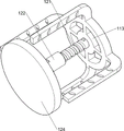
Optionally, the stamping mechanism comprises a stamping frame, an air cylinder, a stabilizing frame and a stamping die, the stamping frame is arranged on one side of the top of the mounting plate, the air cylinder is arranged on the upper portion of the stamping frame, the stabilizing frame is arranged on a telescopic rod of the air cylinder, and the stamping die is arranged at the bottom of the stabilizing frame.
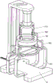
Optionally, the compaction mechanism comprises a screw rod, a nut, a stabilizing block and a compaction block, the screw rod is arranged at the top of the inner wall of the stabilizing frame, the nut is arranged at the lower part of the screw rod in a threaded manner, the stabilizing block is connected to the lower part of the nut, and the compaction block is arranged at the bottom of the stabilizing block.
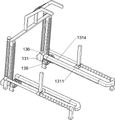
Optionally, the device also comprises a pushing mechanism, the pushing mechanism comprises a guide block, a guide rod, a second spring, a first rack, a guide frame, a clamping sleeve, a conversion frame, a gear, guide slide bars, a connecting block, a push rod, a third spring and a second rack, the top of the mounting plate is symmetrically provided with the guide block, the top of the guide block is provided with the guide rod, the upper part of the guide rod is provided with the first rack in a sliding manner, the second spring is connected between the bottom of the first rack and the guide rod, the guide frame is connected between the tops of the first racks, the clamping sleeve is arranged on the first rack in a sliding manner, the top of the mounting plate is symmetrically provided with the conversion frame, the gear is arranged on the conversion frame in a rotating manner, the outer gears are matched with the first racks on the same side, the top of the mounting plate is symmetrically provided with the guide slide bars, the guide slide bars are provided with the connecting blocks in a sliding manner, the top of the connecting block is provided with the push rod, and the third spring is connected between the connecting block and the guide slide bars, the inner sides of the connecting blocks are provided with second racks.
Optionally, the material returning mechanism comprises a material returning frame, a material returning ring, a material returning guide rail, a sliding block, a material returning plate and a fourth spring, the material returning frame is symmetrically arranged on the mounting plate, the material returning ring is connected between the top of the material returning frame, the material returning guide rail is arranged on the upper portion of the material returning frame, the sliding block is arranged on the material returning guide rail in a sliding mode, the material returning plate is connected between the sliding blocks, and the fourth spring is connected between the sliding block and the material returning guide rail.
Optionally, the material returning rack is further provided with a limiting mechanism, the limiting mechanism comprises a limiting sleeve, a third limiting plate and a screw rod, the limiting sleeve is arranged on one side of the material returning rack, the third limiting plate is connected between the limiting sleeves in a sliding mode, and the screw rod is installed on two sides of the third limiting plate in a threaded mode.
Optionally, the material returning frame is characterized by further comprising a guide mechanism, the guide mechanism comprises a vertical plate, L-shaped rods and clamping blocks, the L-shaped rods are symmetrically arranged at the top of the material returning frame, the vertical plates are connected between the tops of the L-shaped rods on the same side in the transverse direction, and the clamping blocks are arranged at the tops of the vertical plates.
Optionally, the compacted cake is made of iron.
The invention has the beneficial effects that: 1. the stamping die moves downwards to stamp the outer side shape of the tooth blank, and meanwhile, the compaction block stamps the inner side shape of the tooth blank, so that the center stability of the tooth blank is improved, and the later processing is reduced to a certain extent;
2. when the stamping die moves downwards, the second limiting plate is driven to move leftwards to be matched with the first limiting plate to clamp and limit the tooth blank, so that the tooth blank is prevented from shifting in stamping;
3. the stripper plate is driven to move leftwards during stamping, and after stamping, the stripper plate rapidly moves rightwards under the action of a fourth spring to knock a stamping die so as to match stripping of tooth blanks;
4. the third limiting plate can avoid the influence on subsequent operation caused by excessive force application to eject the tooth blank when the second limiting plate is leftwards.
Drawings
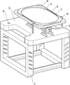
Fig. 1 is a schematic perspective view of the present invention.
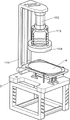
FIG. 2 is a schematic view of a first partial body structure according to the present invention.
FIG. 3 is a schematic view of a second partial body structure according to the present invention.
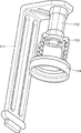
Fig. 4 is a schematic perspective view of a first stamping mechanism according to the present invention.
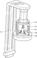
Fig. 5 is a schematic perspective view of a second stamping mechanism according to the present invention.
Fig. 6 is a schematic perspective view of a first embodiment of the compactor mechanism of the present invention.
Fig. 7 is a schematic view of a second embodiment of the compaction mechanism of the invention.
Fig. 8 is a schematic perspective view of a first pushing mechanism according to the present invention.
Fig. 9 is a schematic perspective view of a second pushing mechanism according to the present invention.
Fig. 10 is a schematic perspective view of a third pushing mechanism according to the present invention.
Fig. 11 is a schematic perspective view of a first material returning mechanism according to the present invention.
Fig. 12 is a schematic perspective view of a material returning mechanism according to a second embodiment of the present invention.
Fig. 13 is a schematic perspective view of a first embodiment of the spacing mechanism of the present invention.
Fig. 14 is a schematic perspective view of a second spacing mechanism of the present invention.
Fig. 15 is a perspective view of the guide mechanism of the present invention.
Description of reference numerals: 1_ mounting frame, 2_ mounting plate, 3_ mounting table, 4_ placing plate, 5_ through hole, 6_ first limiting plate, 7_ dispensing rod, 8_ second limiting plate, 9_ first spring, 11_ stamping mechanism, 111_ stamping frame, 112_ cylinder, 113_ stabilizing frame, 114_ stamping die, 12_ compacting mechanism, 121_ screw rod, 122_ nut, 123_ stabilizing block, 124_ compacting block, 13_ pushing mechanism, 131_ guide block, 132_ guide rod, 133_ second spring, 134_ first rack, 135_ guide frame, 136_ ferrule, 137_ conversion frame, 138_ gear, 139_ guide slide rod, 1311_ connecting block, 1312_ push rod, 1313_ third spring, 1314_ second rack, 14_ material returning mechanism, 141_ material returning frame, 142_ material returning ring, 143_ material returning guide rail, 144_ slider, 145_ material returning plate, 146_ fourth spring, 15_ limiting mechanism, 151_ limiting sleeve, 152_ third limiting plate, 153_ screw, 16_ guide mechanism, 161_ riser, 162_ L-shaped rod, 163_ clamp.
Detailed Description
The following description is only a preferred embodiment of the present invention, and does not limit the scope of the present invention.
Example 1
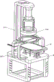
The utility model provides a tooth is punching press forming device for embryo, as shown in fig. 1-15, including mounting bracket 1, mounting panel 2, mount table 3, place board 4, first limiting plate 6, dispensing rod 7, second limiting plate 8, first spring 9, punching press mechanism 11 and compacting mechanism 12, 1 top of mounting bracket is equipped with mounting panel 2, 2 top right sides of mounting panel are equipped with mount table 3, 3 tops of mount table are equipped with places board 4, the symmetry is opened around 2 top left sides of mounting panel has through-hole 5, place 4 top left sides of board and be equipped with first limiting plate 6, 6 right sides of first limiting plate front and back symmetric connection have dispensing rod 7, sliding type connection has second limiting plate 8 between dispensing rod 7 right sides, all be connected with first spring 9 between 8 left sides of second limiting plate and the dispensing rod 7, 2 top left sides of mounting panel is equipped with punching press mechanism 11, be connected with compacting mechanism 12 on the punching press mechanism 11.
The stamping mechanism 11 comprises a stamping frame 111, an air cylinder 112, a stabilizing frame 113 and a stamping die 114, wherein the stamping frame 111 is arranged on the left side of the top of the mounting plate 2, the air cylinder 112 is arranged on the upper portion of the stamping frame 111, the stabilizing frame 113 is arranged at the bottom of an expansion link of the air cylinder 112, and the stamping die 114 is arranged at the bottom of the stabilizing frame 113.
The compacting mechanism 12 comprises a screw rod 121, a nut 122, a stabilizing block 123 and a compacting block 124, the screw rod 121 is arranged at the top of the inner wall of the stabilizing frame 113, the nut 122 is arranged at the lower part of the screw rod 121 in a threaded manner, the stabilizing block 123 is connected to the lower part of the nut 122, and the compacting block 124 is arranged at the bottom of the stabilizing block 123.
The worker can adjust the compaction block 124 according to the depth of the recess required in the tooth blank, the nut 122 is rotated to drive the stabilizing block 123 and the compaction block 124 to move up and down, after the adjustment is completed, the tooth blank is placed on the top of the placing plate 4 and is positioned between the first limiting plate 6 and the second limiting plate 8, the second limiting plate 8 is manually pushed to move left to be matched with the first limiting plate 6 to clamp the tooth blank, the first spring 9 is compressed, then the cylinder 112 is started, the telescopic rod of the cylinder 112 extends to drive the stamping die 114 to move downwards through the stabilizing frame 113, and simultaneously the screw rod 121 and the above components are driven to move downwards, because the horizontal position of the compaction block 124 is lower than that of the stamping die 114, the compaction block 124 can firstly stamp the inner side of the tooth blank, then the stamping die 114 moves downwards to stamp the outer side of the tooth blank, the telescopic rod of the cylinder 112 is shortened to drive the stabilizing frame 113 and the stamping die 114 and the compaction block 124 above to move upwards to reset, that is, after the punching is finished, the second limiting plate 8 is not pushed any more, the first spring 9 resets to drive the second limiting plate 8 to move rightwards for resetting, the formed tooth blank is taken out, and after all the tooth blanks are manufactured, the operation of the air cylinder 112 is stopped.
The pushing mechanism 13 is further included, the pushing mechanism 13 includes a guide block 131, a guide rod 132, a second spring 133, a first rack 134, a guide frame 135, a sleeve chuck 136, a conversion frame 137, a gear 138, a guide slide bar 139, a connecting block 1311, a push rod 1312, a third spring 1313 and a second rack 1314, the guide block 131 is symmetrically arranged on the left side of the top of the mounting plate 2 in front and back, the guide rod 132 is arranged on the top of the guide block 131, the first rack 134 is arranged on the right side of the upper portion of the guide rod 132 in a sliding manner, the first rack 134 is matched with the through hole 5 in a sliding manner, the second spring 133 is connected between the bottom of the first rack 134 and the guide rod 132, the guide frame 135 is connected between the tops of the first rack 134, the sleeve chuck 136 is arranged on the first rack 134 in a sliding manner, the top of the sleeve chuck 136 is connected with the second spring 133, the conversion frame 137 is symmetrically arranged on the left side of the top of the mounting plate 2, the conversion frame 137 is arranged on the right side of the through hole 5, the gear 138 is symmetrically arranged on the conversion frame 137 in a front and back manner, the outer side gears 138 are all matched with the first racks 134 on the same side, guide sliding rods 139 are symmetrically arranged in front and back of the top of the mounting plate 2, connecting blocks 1311 are arranged on the guide sliding rods 139 in a sliding mode, push rods 1312 are arranged on the tops of the connecting blocks 1311, the second limiting plate 8 is clamped by the push rods 1312, third springs 1313 are connected between the right sides of the connecting blocks 1311 and the guide sliding rods 139, second racks 1314 are arranged on the inner sides of the connecting blocks 1311, and the second racks 1314 are matched with the inner side gears 138.
Still including material returned mechanism 14, material returned mechanism 14 is including material returned frame 141, material returned ring 142, material returned guide rail 143, slider 144, material returned board 145 and fourth spring 146, mounting panel 2 symmetry is equipped with material returned frame 141 around, be connected with material returned ring 142 between material returned frame 141 top, material returned frame 141 upper portion left side all is equipped with material returned guide rail 143, material returned guide rail 143 is last all to be slided and is equipped with slider 144, be connected with material returned board 145 between the slider 144, slider 144 left side all with material returned guide rail 143 between be connected with fourth spring 146.
After the tooth blank is placed, the stabilizing frame 113 moves downwards to press the guide frame 135 to move downwards, thereby driving the first rack 134 to move downwards to contact with the outer gear 138, the second spring 133 is compressed, the outer gear 138 drives the inner gear 138 to rotate through the switching frame 137 to be matched with the second rack 1314, the second rack 1314 moves leftwards to drive the push rod 1312 to move leftwards through the connecting block 1311, the third spring 1313 is stretched, and then the second limit plate 8 is driven to move leftwards to clamp the tooth blank, the human hand is not needed to push, after the forming is finished, the stabilizing frame 113 moves upwards to reset, the guide frame 135 is not stressed any more, the second spring 133 resets to drive the first rack 134 to move upwards to reset, the gear 138 drives the second rack 1314 to move rightwards to reset, and further drives the connecting block 1311 and the push rod 1312 to move rightwards to reset, the third spring 1313 resets, and at the moment, the second limiting plate 8 is not stressed to move rightwards to reset under the action of the first spring 9 any more; during the punching process, the material returning ring 142 can prevent the tooth blank from deforming during the punching process, the push rod 1312 can extrude the material returning plate 145 to move left when moving left, and then the slide block 144 drives the fourth spring 146 to be compressed, when the punching process is finished, the push rod 1312 moves right to reset and does not apply force with the material returning plate 145, the fourth spring 146 resets and drives the material returning plate 145 to move right rapidly through the slide block 144 to knock the punching die 114, and the tooth blank is prevented from being clamped in the punching die 114 and is inconvenient to feed.
Still including stop gear 15, stop gear 15 is including stop collar 151, third limiting plate 152 and screw rod 153, and material returned frame 141 left side all is equipped with stop collar 151, and stop collar 151 is located material returned guide rail 143 top, and sliding connection has third limiting plate 152 between the stop collar 151, and screw rod 153 is installed to the equal screw thread formula in both sides around third limiting plate 152.
Still including guiding mechanism 16, guiding mechanism 16 is equipped with L type pole 162 including riser 161, L type pole 162 and clamp splice 163, and it is equipped with L type pole 162 to move back the equal bilateral symmetry in work or material rest 141 top, all is connected with riser 161 between the L type pole 162 top of horizontal homonymy, and riser 161 top all is equipped with clamp splice 163, and clamp splice 163 all with stabilizer 113 sliding connection.
The worker adjusts the position of the third limiting plate 152 in advance according to the shape of the tooth blank, the screw 153 is rotated to be separated from the third limiting plate 152, the third limiting plate 152 is driven to move left and right to be adjusted, after the adjustment is finished, the screw 153 is rotated to reset, the position of the third limiting plate 152 is fixed, and therefore the tooth blank is prevented from being ejected when the second limiting plate 8 moves left; the stabilizing frame 113 can precisely move downwards through the secondary guiding of the clamping block 163 to punch tooth blanks, so as to prevent the punching die 114 from moving downwards to damage parts at wrong angles.
The above description is only for the purpose of illustrating the preferred embodiments of the present invention and is not to be construed as limiting the invention, and any modifications, equivalents, improvements and the like that fall within the spirit and principle of the present invention are intended to be included therein.
Claims (8)
1. A tooth is punching press forming device for embryo, its characterized in that, including: the tooth blank punching machine comprises a mounting frame (1), a mounting plate (2), a mounting platform (3), a placing plate (4), a first limiting plate (6), a dispensing rod (7), a second limiting plate (8), a first spring (9), a punching mechanism (11) and a compacting mechanism (12), wherein the mounting plate (2) is arranged at the top of the mounting frame (1), the mounting platform (3) is arranged on one side of the top of the mounting plate (2), the placing plate (4) is arranged at the top of the mounting platform (3), through holes (5) are symmetrically formed in one side of the top of the mounting plate (2), the first limiting plate (6) is arranged on one side of the top of the placing plate (4), the dispensing rod (7) is symmetrically connected to the first limiting plate (6), the second limiting plate (8) for clamping tooth blanks is connected between the dispensing rods (7) in a sliding mode, the first spring (9) is connected between the second limiting plate (8) and the dispensing rod (7), the punching mechanism (11) for punching the shape of the outer side of the tooth blanks is arranged on one side of the top of the mounting plate (2), the stamping mechanism (11) is connected with a compacting mechanism (12) for stamping the inner shape of the tooth blank.
2. A blank tooth press forming apparatus according to claim 1, wherein the press mechanism (11) comprises: the stamping die comprises a stamping frame (111), an air cylinder (112), a stabilizing frame (113) and a stamping die (114), wherein the stamping frame (111) is arranged on one side of the top of the mounting plate (2), the air cylinder (112) is arranged on the upper portion of the stamping frame (111), the stabilizing frame (113) is arranged on a telescopic rod of the air cylinder (112), and the stamping die (114) is arranged at the bottom of the stabilizing frame (113).
3. A blank tooth press-forming apparatus as claimed in claim 2, wherein the compacting means (12) comprises: the screw rod (121) is arranged at the top of the inner wall of the stabilizing frame (113), the nut (122) is arranged at the lower part of the screw rod (121) in a threaded mode, the stabilizing block (123) is connected to the lower part of the nut (122), and the compacting block (124) is arranged at the bottom of the stabilizing block (123).
4. A blank tooth punching and forming apparatus according to claim 3, further comprising a pushing mechanism (13), wherein the pushing mechanism (13) comprises: the guide block (131), the guide rod (132), the second spring (133), the first rack (134), the guide frame (135), the clamping sleeve (136), the conversion frame (137), the gear (138), the guide slide rod (139), the connecting block (1311), the push rod (1312), the third spring (1313) and the second rack (1314), the guide block (131) is symmetrically arranged at the top of the mounting plate (2), the guide rod (132) is arranged at the top of the guide block (131), the first rack (134) is arranged at the upper part of the guide rod (132) in a sliding manner, the second spring (133) is connected between the bottom of the first rack (134) and the guide rod (132), the guide frame (135) is connected between the tops of the first rack (134), the clamping sleeve (136) is arranged on the first rack (134) in a sliding manner, the conversion frame (137) is symmetrically arranged at the top of the mounting plate (2), the gear (138) is symmetrically arranged on the conversion frame (137) in a rotating manner, outside gear (138) all with the cooperation of the first rack (134) of homonymy, mounting panel (2) top symmetry is equipped with direction slide bar (139), all is equipped with connecting block (1311) on direction slide bar (139) slidingly, and connecting block (1311) top all is equipped with push rod (1312), and connecting block (1311) all is connected with third spring (1313) with between direction slide bar (139), and connecting block (1311) inboard all is equipped with second rack (1314).
5. The tooth blank punching and forming device according to claim 4, further comprising a material returning mechanism (14), wherein the material returning mechanism (14) comprises: the material returning device comprises a material returning frame (141), material returning rings (142), material returning guide rails (143), sliding blocks (144), material returning plates (145) and a fourth spring (146), wherein the material returning frame (141) is symmetrically arranged on a mounting plate (2), the material returning rings (142) are connected between the tops of the material returning frame (141), the material returning guide rails (143) are arranged on the upper portions of the material returning frame (141), the sliding blocks (144) are arranged on the material returning guide rails (143) in a sliding mode, the material returning plates (145) are connected between the sliding blocks (144), and the fourth spring (146) is connected between the sliding blocks (144) and the material returning guide rails (143).
6. The tooth blank punching and forming device according to claim 5, further comprising a limiting mechanism (15), wherein the limiting mechanism (15) comprises: stop collar (151), third limiting plate (152) and screw rod (153), material returned frame (141) one side all is equipped with stop collar (151), and sliding connection has third limiting plate (152) between stop collar (151), and screw rod (153) are installed to the equal screw thread formula in third limiting plate (152) both sides.
7. The blank tooth punching and forming device according to claim 6, further comprising a guide mechanism (16), wherein the guide mechanism (16) comprises: riser (161), L type pole (162) and clamp splice (163), material returned frame (141) top all symmetry is equipped with L type pole (162), all is connected with riser (161) between the L type pole (162) top of horizontal homonymy, and riser (161) top all is equipped with clamp splice (163).
8. A blank tooth punch forming apparatus in accordance with claim 7 wherein the compact (124) is iron.
Priority Applications (1)
| Application Number | Priority Date | Filing Date | Title |
|---|---|---|---|
| CN202111482260.3A CN114309332A (en) | 2021-12-07 | 2021-12-07 | Tooth is stamping forming device for embryo |
Applications Claiming Priority (1)
| Application Number | Priority Date | Filing Date | Title |
|---|---|---|---|
| CN202111482260.3A CN114309332A (en) | 2021-12-07 | 2021-12-07 | Tooth is stamping forming device for embryo |
Publications (1)
| Publication Number | Publication Date |
|---|---|
| CN114309332A true CN114309332A (en) | 2022-04-12 |
Family
ID=81047846
Family Applications (1)
| Application Number | Title | Priority Date | Filing Date |
|---|---|---|---|
| CN202111482260.3A Pending CN114309332A (en) | 2021-12-07 | 2021-12-07 | Tooth is stamping forming device for embryo |
Country Status (1)
| Country | Link |
|---|---|
| CN (1) | CN114309332A (en) |
Cited By (1)
| Publication number | Priority date | Publication date | Assignee | Title |
|---|---|---|---|---|
| CN118218492A (en) * | 2024-05-22 | 2024-06-21 | 南通平华风机科技有限公司 | Pipe fitting stamping variable die guide structure for hardware processing |
Citations (8)
| Publication number | Priority date | Publication date | Assignee | Title |
|---|---|---|---|---|
| CN207359685U (en) * | 2017-03-31 | 2018-05-15 | 苏州市桑林汽车配件有限公司 | A kind of automobile handware stamping equipment of automatic positioning |
| CN109382444A (en) * | 2018-10-26 | 2019-02-26 | 江苏筑隆模具有限公司 | A kind of accurate air-conditioning plate processing mold of stable structure punching press |
| CN210045895U (en) * | 2019-03-20 | 2020-02-11 | 重庆鼎诚电子元件有限公司 | Special-shaped electrode pressing device |
| CN210907722U (en) * | 2019-11-18 | 2020-07-03 | 昆山泰立德精密机械有限公司 | Necking die in stainless steel transfer stretching die |
| CN111531044A (en) * | 2020-05-13 | 2020-08-14 | 泰州市双宇汽车零部件有限公司 | Stamping device for automobile part machining and stamping method thereof |
| CN112828160A (en) * | 2021-01-20 | 2021-05-25 | 韦金林 | Circular metal gasket stamping forming equipment for manufacturing high-end equipment |
| CN113020432A (en) * | 2021-02-25 | 2021-06-25 | 合肥正特机械有限公司 | Staple bolt stamping die based on autoloading |
| CN213645649U (en) * | 2020-10-28 | 2021-07-09 | 河北明旺建材科技有限公司 | Workpiece positioning device for punch press |
-
2021
- 2021-12-07 CN CN202111482260.3A patent/CN114309332A/en active Pending
Patent Citations (8)
| Publication number | Priority date | Publication date | Assignee | Title |
|---|---|---|---|---|
| CN207359685U (en) * | 2017-03-31 | 2018-05-15 | 苏州市桑林汽车配件有限公司 | A kind of automobile handware stamping equipment of automatic positioning |
| CN109382444A (en) * | 2018-10-26 | 2019-02-26 | 江苏筑隆模具有限公司 | A kind of accurate air-conditioning plate processing mold of stable structure punching press |
| CN210045895U (en) * | 2019-03-20 | 2020-02-11 | 重庆鼎诚电子元件有限公司 | Special-shaped electrode pressing device |
| CN210907722U (en) * | 2019-11-18 | 2020-07-03 | 昆山泰立德精密机械有限公司 | Necking die in stainless steel transfer stretching die |
| CN111531044A (en) * | 2020-05-13 | 2020-08-14 | 泰州市双宇汽车零部件有限公司 | Stamping device for automobile part machining and stamping method thereof |
| CN213645649U (en) * | 2020-10-28 | 2021-07-09 | 河北明旺建材科技有限公司 | Workpiece positioning device for punch press |
| CN112828160A (en) * | 2021-01-20 | 2021-05-25 | 韦金林 | Circular metal gasket stamping forming equipment for manufacturing high-end equipment |
| CN113020432A (en) * | 2021-02-25 | 2021-06-25 | 合肥正特机械有限公司 | Staple bolt stamping die based on autoloading |
Cited By (1)
| Publication number | Priority date | Publication date | Assignee | Title |
|---|---|---|---|---|
| CN118218492A (en) * | 2024-05-22 | 2024-06-21 | 南通平华风机科技有限公司 | Pipe fitting stamping variable die guide structure for hardware processing |
Similar Documents
| Publication | Publication Date | Title |
|---|---|---|
| CN208513448U (en) | A kind of porous stamping die of five metalworkings | |
| CN114309332A (en) | Tooth is stamping forming device for embryo | |
| CN217166119U (en) | Auxiliary structure of stamping die | |
| CN110586753A (en) | Stamping equipment who possesses garbage collection function | |
| CN212652524U (en) | Stamping die convenient to dismouting stamping die head | |
| CN109226467A (en) | Abnormal workpieces punching tool and its hole-punching method | |
| CN112496150A (en) | Mechanical equipment for punching plates | |
| CN218926037U (en) | Pressing plate structure of mold frame | |
| CN209829996U (en) | Back row base control support mould | |
| CN208913007U (en) | A kind of machine die ejecting structure | |
| CN111590006A (en) | Briquetting machine casting equipment for briquetting casting materials | |
| CN214773624U (en) | Die holder convenient for replacing die core | |
| CN210817463U (en) | Demoulding device of template in powder forming machine | |
| CN210651081U (en) | Mould locking device for precise electronic cutting die | |
| CN211888570U (en) | Hardware stamping equipment | |
| CN210552068U (en) | Mould extractor | |
| CN216911797U (en) | Ejection mechanism of automobile drawing die | |
| CN221790835U (en) | Hardware stamping discharging structure | |
| CN221639280U (en) | Hardware mould convenient to fixed processing product | |
| CN220679088U (en) | Industrial automatic control stamping forming equipment | |
| CN218693065U (en) | Punch press with auxiliary positioning device | |
| CN216263040U (en) | Core-pulling rubber head vehicle key blank mold | |
| CN220659031U (en) | A mould for producing cover | |
| CN219276763U (en) | Novel automatic press | |
| CN220278126U (en) | Workpiece stamping device for mechanical parts |
Legal Events
| Date | Code | Title | Description |
|---|---|---|---|
| PB01 | Publication | ||
| PB01 | Publication | ||
| SE01 | Entry into force of request for substantive examination | ||
| SE01 | Entry into force of request for substantive examination |