CN114249552B - Superfine steel slag powder based on 3D printing technology and preparation method thereof - Google Patents
Superfine steel slag powder based on 3D printing technology and preparation method thereof Download PDFInfo
- Publication number
- CN114249552B CN114249552B CN202111599872.0A CN202111599872A CN114249552B CN 114249552 B CN114249552 B CN 114249552B CN 202111599872 A CN202111599872 A CN 202111599872A CN 114249552 B CN114249552 B CN 114249552B
- Authority
- CN
- China
- Prior art keywords
- ring
- unit
- steel slag
- slag powder
- transverse
- Prior art date
- Legal status (The legal status is an assumption and is not a legal conclusion. Google has not performed a legal analysis and makes no representation as to the accuracy of the status listed.)
- Active
Links
Images


Classifications
-
- C—CHEMISTRY; METALLURGY
- C04—CEMENTS; CONCRETE; ARTIFICIAL STONE; CERAMICS; REFRACTORIES
- C04B—LIME, MAGNESIA; SLAG; CEMENTS; COMPOSITIONS THEREOF, e.g. MORTARS, CONCRETE OR LIKE BUILDING MATERIALS; ARTIFICIAL STONE; CERAMICS; REFRACTORIES; TREATMENT OF NATURAL STONE
- C04B18/00—Use of agglomerated or waste materials or refuse as fillers for mortars, concrete or artificial stone; Treatment of agglomerated or waste materials or refuse, specially adapted to enhance their filling properties in mortars, concrete or artificial stone
- C04B18/04—Waste materials; Refuse
- C04B18/14—Waste materials; Refuse from metallurgical processes
- C04B18/141—Slags
- C04B18/142—Steelmaking slags, converter slags
-
- B—PERFORMING OPERATIONS; TRANSPORTING
- B33—ADDITIVE MANUFACTURING TECHNOLOGY
- B33Y—ADDITIVE MANUFACTURING, i.e. MANUFACTURING OF THREE-DIMENSIONAL [3D] OBJECTS BY ADDITIVE DEPOSITION, ADDITIVE AGGLOMERATION OR ADDITIVE LAYERING, e.g. BY 3D PRINTING, STEREOLITHOGRAPHY OR SELECTIVE LASER SINTERING
- B33Y70/00—Materials specially adapted for additive manufacturing
-
- C—CHEMISTRY; METALLURGY
- C04—CEMENTS; CONCRETE; ARTIFICIAL STONE; CERAMICS; REFRACTORIES
- C04B—LIME, MAGNESIA; SLAG; CEMENTS; COMPOSITIONS THEREOF, e.g. MORTARS, CONCRETE OR LIKE BUILDING MATERIALS; ARTIFICIAL STONE; CERAMICS; REFRACTORIES; TREATMENT OF NATURAL STONE
- C04B20/00—Use of materials as fillers for mortars, concrete or artificial stone according to more than one of groups C04B14/00 - C04B18/00 and characterised by shape or grain distribution; Treatment of materials according to more than one of the groups C04B14/00 - C04B18/00 specially adapted to enhance their filling properties in mortars, concrete or artificial stone; Expanding or defibrillating materials
- C04B20/02—Treatment
- C04B20/026—Comminuting, e.g. by grinding or breaking; Defibrillating fibres other than asbestos
-
- Y—GENERAL TAGGING OF NEW TECHNOLOGICAL DEVELOPMENTS; GENERAL TAGGING OF CROSS-SECTIONAL TECHNOLOGIES SPANNING OVER SEVERAL SECTIONS OF THE IPC; TECHNICAL SUBJECTS COVERED BY FORMER USPC CROSS-REFERENCE ART COLLECTIONS [XRACs] AND DIGESTS
- Y02—TECHNOLOGIES OR APPLICATIONS FOR MITIGATION OR ADAPTATION AGAINST CLIMATE CHANGE
- Y02W—CLIMATE CHANGE MITIGATION TECHNOLOGIES RELATED TO WASTEWATER TREATMENT OR WASTE MANAGEMENT
- Y02W30/00—Technologies for solid waste management
- Y02W30/50—Reuse, recycling or recovery technologies
- Y02W30/91—Use of waste materials as fillers for mortars or concrete
Landscapes
- Chemical & Material Sciences (AREA)
- Engineering & Computer Science (AREA)
- Ceramic Engineering (AREA)
- Materials Engineering (AREA)
- Structural Engineering (AREA)
- Organic Chemistry (AREA)
- Manufacturing & Machinery (AREA)
- Environmental & Geological Engineering (AREA)
- Civil Engineering (AREA)
- Crushing And Grinding (AREA)
Abstract
The invention belongs to the technical field of concrete, and particularly relates to superfine steel slag powder for a 3D printing technology and a preparation method thereof. The invention grinds the coarse steel slag powder raw material to the grain diameter less than or equal to 6.5 mu m and the specific surface area of 720-750m 2 The/kg mode ensures that the steel slag powder meets the requirement of superfine, and can be quickly combined and cured with cement in concrete. In addition, the invention also provides a circular blowing type ball mill which structurally comprises a support ring unit, a middle rotating ring unit, a grinding cylinder unit, a feeding cylinder unit and a sliding pipe unit and has the effects of sufficient grinding strength and higher grinding efficiency.
Description
Technical Field
The invention belongs to the technical field of concrete, and particularly relates to superfine steel slag powder for a 3D printing technology and a preparation method thereof.
Background
The concrete 3D printing technology is a new technology which utilizes a computer to perform layered modeling, transmits a program command, and is characterized in that an industrial robot is controlled to repeatedly lay materials layer by layer so as to build a free-form building structure.
Therefore, the technology is mainly divided into three parts, namely a mechanical equipment layer, a computer program layer and a concrete material layer. Wherein, the requirements for the concrete are mainly two: the setting time is short, the strength is developed quickly, and therefore, a plurality of concrete materials special for the 3D printing technology are available at present.
For example, a Chinese patent with patent publication No. CN 108623268A and publication No. 2018.10.09 discloses a self-heat-preservation load-bearing concrete based on 3D printing performance, which is prepared from the following components: 600-800 parts of quick-hardening sulphoaluminate cement; 90-130 parts of steel slag powder; 40-80 parts of fly ash; 130-180 parts of silica fume; 2000-3000 parts of quartz sand; 0-5 parts of an accelerator; 0-8 parts of a retarder; 4-7 parts of a water reducing agent; 8-13 parts of latex powder; 0.4-0.8 part of cellulose ether; 2-5 parts of water glass; 250-300 parts of water; 6-10 parts of polypropylene fiber; and (4) vitrification of the micro-beads.
Although the concrete disclosed by the invention has the advantage of relatively short setting time, the strength increase speed is not enough, namely the requirement of fast strength development does not reach the standard, and the reason is that the fineness of the steel slag powder is insufficient and too large, and the concrete is not easy to be quickly combined and cured with the cement.
Therefore, the superfine steel slag powder special for the 3D printing technology is urgently needed at present, the particle size of the superfine steel slag powder is ensured not to exceed 6.5 mu m to the maximum extent, and the requirement of superfine is met.
On the other hand, the existing grinding equipment for steel slag powder, such as the chinese utility model patent with patent publication No. CN214554065U and publication No. 2021.11.02, discloses an environment-friendly steel slag powder ball mill device, which comprises a frame, a driving device, a ball mill cylinder and an outer cover; the ball grinding cylinder is rotationally connected to the rack, a feed port is formed in the ball grinding cylinder, and a cover plate is arranged at the feed port; the driving device is connected to the frame and connected to one end of the ball grinding cylinder; the outer cover is connected to the rack, a door body is arranged on the outer cover, and the ball grinding cylinder is positioned on the inner side of the outer cover; the frame comprises a plurality of cross beams and supporting legs, the cross beams are fixedly connected to form a rectangular structure, and the supporting legs are fixedly connected to the bottom ends of the cross beams; the two ends of the ball grinding cylinder are fixedly connected with rotating shafts, the top end of the cross beam is fixedly connected with a support, and the rotating shafts are connected to the support through bearing seats.
However, the ball-milling device in this utility model patent, it is in the use, has following two weak points at least, and the grinding that finally leads to superfine steel slag powder prepares the effect not good:
firstly, the air blowing function is lacked, so that qualified steel slag powder cannot pass through a screen rapidly and still occupies abrasive material resources, and the steel slag powder with overlarge particle size cannot be rapidly and fully ground;
secondly, the efficiency of the feeding operation and the rotating operation is not high, and the grinding cylinder cannot be rotated sufficiently.
Therefore, in order to obtain ultrafine steel slag powder, a novel ball mill having high grinding efficiency and sufficient grinding needs to be used in the preparation method.
Disclosure of Invention
The invention provides superfine steel slag powder based on a 3D printing technology, which can be prepared by grinding a coarse steel slag powder raw material to a particle size of less than or equal to 6.5 mu m and a specific surface area of 720-750m 2 The/kg mode ensures that the steel slag powder meets the requirement of superfine, and can be quickly combined and cured with cement in concrete.
In addition, the invention also provides a circular blowing type ball mill which structurally comprises a support ring unit, a middle rotating ring unit, a grinding cylinder unit, a feeding cylinder unit and a sliding pipe unit and has the functions of sufficient grinding strength and higher grinding efficiency.
The technical scheme adopted by the invention for solving the problems is as follows: ultrafine steel slag powder based on 3D printing technology, wherein the particle size of the ultrafine steel slag powder is less than or equal to 6.5 mu m, and the specific surface area of the ultrafine steel slag powder is 720-750m 2 /kg。
A preparation method of superfine steel slag powder based on a 3D printing technology comprises the steps of grinding a steel slag powder raw material by using a circular air blowing type ball mill for 5-12min, and enabling the mesh number of a ground screen to be 2000 meshes.
The further preferred technical scheme is as follows: the structure of the circumferential air blowing type ball mill comprises a support ring unit externally connected with an air blowing pipe, a middle rotating ring unit arranged in the support ring unit, a grinding cylinder unit arranged at one side position of the middle rotating ring unit, a feeding cylinder unit arranged at the other side position of the middle rotating ring unit, and a sliding pipe unit arranged in the feeding cylinder unit and used for enabling materials to enter the grinding cylinder unit in a mode of inserting the grinding cylinder unit.
The further preferred technical scheme is as follows: the support ring unit includes fixed ring, sets up on the fixed ring inner ring face and be used for supporting the middle part annular of rotatory ring unit in middle part sets up on the fixed ring inner ring face and be located respectively two side annular of middle part annular both sides position department set up in the side annular in and be used for sealed lubricating grease when blowing, and set up middle part annular and one of them just outer inlet port of gas blow pipe that links between the side annular.
The further preferred technical scheme is as follows: the middle rotating ring unit comprises a ring body arranged on the ring groove in the middle, a radial column arranged on the inner ring surface of the ring body, and a transverse column arranged on the radial column and used for fixing the grinding cylinder unit and the charging cylinder unit respectively.
The further preferred technical scheme is as follows: the grinding cylinder unit comprises a transverse main cylinder arranged on the transverse column, an air inlet feed hole arranged on an end plate of the transverse main cylinder, a main sealing ring arranged on the outer annular surface of the transverse main cylinder and inserted into the side annular groove, and annular teeth arranged on the exposed annular surface of the main sealing ring and externally connected with a driving gear.
The further preferred technical scheme is as follows: reinforced barrel unit is including setting up horizontal vice barrel on the horizontal post sets up horizontal vice barrel end board is gone up and is close to the discharge opening of air inlet feed port sets up the feed port on the horizontal vice barrel opposite side end board sets up apron on the feed port, and sets up on the outer anchor ring of horizontal vice barrel and insert another the vice sealing ring of side annular.
The further preferred technical scheme is as follows: the sliding pipe unit comprises a clamping pipe inserted in the discharge hole and an elastic pipe arranged between the clamping pipe and the feed hole.
The further preferred technical scheme is as follows: the sliding pipe unit also comprises a limiting ring arranged between the outer ring surface of the clamping pipe and the inner ring surface of the transverse auxiliary cylinder body, and a sliding grip arranged on the inner ring surface of the clamping pipe.
The further preferred technical scheme is as follows: the air inlet feed port, the discharge hole and the feed hole are circular holes, and the aperture of the air inlet feed port is equal to that of the discharge hole and is larger than that of the feed hole.
The present invention has the following advantages.
Firstly, the parameters of the particle size and the specific surface area of the steel slag powder are sufficient and suitable, the superfine specification requirement is ensured, the steel slag powder can be quickly cured in concrete, and the performance requirement of the concrete special for the 3D printing technology is met.
Secondly, the blowing intensity of the circular blowing type ball mill is high and sufficient, the steel slag powder with qualified grain diameter can be discharged quickly, and the efficiency of grinding operation is improved.
Thirdly, the air blowing operation can also stir the materials and the grinding materials, so that the grinding speed is further improved.
Fourthly, the ball mill has the high-strength function of blowing before the slip of slip pipe unit, and the function of blowing is closed after the slip, and the feeding operation is stable effective, guarantees that two actions of a feeding of blowing do not influence each other.
Fifthly, the air blowing channel has enough air tightness, the ball mill is simple and stable in rotating operation, and external circuits are not easy to twist and knot.
Drawings
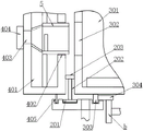
FIG. 1 is a schematic structural diagram of a hoop blowing ball mill according to the present invention.
Fig. 2 is a schematic structural view of the support ring unit according to the present invention.
Fig. 3 is a schematic view showing the positional structure of the middle rotating ring unit, the grinding cylinder unit and the charging cylinder unit in the present invention.
FIG. 4 is a schematic view of the use of the sliding tube unit for feeding in the present invention.
In the drawings, the reference numerals denote the following components: the device comprises an air blowing pipe a, a driving gear b, a support ring unit 1, a middle rotating ring unit 2, a grinding cylinder unit 3, a feeding cylinder unit 4, a sliding pipe unit 5, a fixed ring 101, a middle ring groove 102, a side ring groove 103, lubricating grease 104, an air inlet 105, a ring body 201, a radial column 202, a transverse column 203, a transverse main cylinder 301, an air inlet feed hole 302, a main sealing ring 303, a ring tooth 304, a transverse auxiliary cylinder 401, a discharge hole 402, a feed hole 403, a cover plate 404, an auxiliary sealing ring 405, a clamping pipe 501, an elastic pipe 502, a limiting ring 503 and a sliding handle 504.
Detailed Description
The following description is only a preferred embodiment of the present invention and is not intended to limit the scope of the present invention.
Example (b): as shown in attached drawings 1-4, the superfine steel slag powder for 3D printing technology has a particle size of 6.5 μm or less and a specific surface area of 720-750m 2 /kg。
In this embodiment, the ultrafine steel slag powder has a sufficiently fine particle size and a suitable specific surface area, and can be rapidly combined and cured with cement, so as to meet the "strength development speed" standard required by 3D printing technology.
A preparation method of superfine steel slag powder based on a 3D printing technology comprises the steps of grinding a steel slag powder raw material by using a circumferential air blowing type ball mill for 5-12min, and enabling the mesh number of a screen mesh after grinding to be 2000 meshes.
In this embodiment, the corresponding passing particle size of the 2000-mesh screen is 6.5 μm, and the whole grinding process from the time when the steel slag powder raw material meets the abrasive to the time when the steel slag powder raw material passes through the screen is 5-12 min.
The structure of the circumferential air blowing type ball mill comprises a support ring unit 1 externally connected with an air blowing pipe a, a middle rotating ring unit 2 arranged in the support ring unit 1, a grinding cylinder unit 3 arranged at one side position of the middle rotating ring unit 2, a feeding cylinder unit 4 arranged at the other side position of the middle rotating ring unit 2, and a sliding pipe unit 5 which is arranged in the feeding cylinder unit 4 and is used for enabling materials to enter the grinding cylinder unit 3 in a mode of inserting the grinding cylinder unit 3.
In the present embodiment, the general usage and advantages of the hoop blowing ball mill are as follows.
Firstly, when the grinding cylinder unit 3 is started, the sliding pipe unit 5 is positioned at one side close to the grinding cylinder unit 3, the grinding cylinder unit 3 is butted with the charging cylinder unit 4, then coarse steel slag powder raw materials are poured into the charging cylinder unit 4, and the raw materials can slide into the grinding cylinder unit 3 and are converged with abrasive materials.
Secondly, the sliding pipe unit 5 is pulled back to one side far away from the grinding cylinder unit 3, at the moment, the air blowing channel at the middle rotating ring unit 2 is switched to be opened from the previous closing, the grinding cylinder unit 3 is driven by a motor gear, the supporting ring unit 1 can blow air as required, at the moment, the feeding cylinder unit 4 is closed, grinding dust cannot float outwards, and finally the whole grinding and refining operation of the coarse steel slag powder of the batch is finished.
Wherein, the air blowing channel is the support ring unit 1, the middle part rotating ring unit 2 and the grinding cylinder unit 3 in sequence, and the support ring unit 1 is fixed, so that the air blowing pipeline is not easy to generate harmful phenomena such as pipe body knotting and twisting.
Compared with a mode that an air blowing opening is a charging opening in the prior art, the annular air blowing type ball mill has no trouble that an air blowing pipeline needs to be frequently disassembled so as to give way to the charging operation.
Finally, the size of the air inlet and feeding part on the grinding cylinder unit 3 is not limited by the size of the air blowing pipeline, and the grinding cylinder unit 3 can obtain higher air inlet and feeding efficiency.
Support ring unit 1 is in including fixed ring 101, sets up on the fixed ring 101 inner ring face and be used for supporting the middle part is rotated ring unit 2's middle part annular 102, sets up fixed ring 101 inner ring face is last and is located respectively two side annular 103 of middle part annular 102 both sides position department set up in the side annular 103 and be used for sealed grease 104 when blowing, and set up and be in middle part annular 102 and one of them the gas inlet 105 of gas blow pipe a is just even outward between the side annular 103.
In this embodiment, a support frame is further disposed below the fixed ring 101, the middle ring groove 102 is wider than the side ring grooves 103, after all, the middle rotating ring unit 2 is a pressure-bearing part, and the side ring grooves 103 are only used for sealing the inflation channel.
In addition, the grease 104 is a conventional gear grease, which has the following advantages:
firstly, under the premise of relatively small inflation pressure and relatively large viscosity of the grease 104, air is difficult to blow the grease 104 outwards at the side annular groove 103, so that the barrier sealing effect is sufficient;
secondly, when the grinding cylinder unit 3 and the charging cylinder unit 4 rotate in the lubricating grease 104, the resistance is relatively small, in other words, the lubricating grease 104 is the preferable scheme of the bristles;
thirdly, the side annular groove 103 is vertical round, so it is not feasible with liquid seal oil, and the upper part can drop, and the lubricating grease 104 itself is difficult to flow, therefore guarantee vertical round in the side annular groove 103, can both set up steadily lubricating grease 104 guarantees everywhere sealed.
Fourthly, the grease 104 is pre-stored in the side ring groove 103, and the gear on the grinding cylinder unit 3 is obtained in use.
The middle rotating ring unit 2 comprises a ring body 201 arranged on the middle ring groove 102, a radial column 202 arranged on the inner ring surface of the ring body 201, and a transverse column 203 arranged on the radial column 202 and used for fixing the grinding cylinder unit 3 and the charging cylinder unit 4 respectively.
In this embodiment, the outer circumferential surface of the torus 201 is provided with a plurality of circles of balls to ensure a relatively small friction force with the middle ring groove 102, and the number of the radial columns 202 and the transverse columns 203 is 2-10 pairs, the former is used for supporting most of the weight of the whole circular air blowing type ball mill, and the latter is used for fixedly connecting the grinding cylinder unit 3 and the feeding cylinder unit 4.
Therefore, a larger gap between the grinding cylinder unit 3 and the charging cylinder unit 4 is an air inflation channel, and a circle of annular positions can be ventilated, so that the strength of air blowing operation can be ensured to be high, which cannot be achieved by the existing ball mill.
The grinding cylinder unit 3 comprises a transverse main cylinder 301 arranged on the transverse column 203, an air inlet feed hole 302 arranged on an end plate of the transverse main cylinder 301, a main sealing ring 303 arranged on the outer annular surface of the transverse main cylinder 301 and inserted into the side annular groove 103, and annular teeth 304 arranged on the exposed annular surface of the main sealing ring 303 and externally connected with a driving gear b.
In this embodiment, the transverse main cylinder 301 is provided with the 2000-mesh screen, some partition boards, and sufficient and appropriate abrasive materials as required in the prior art manner, and the air inlet feed hole 302 is, as the name implies, both the feeding position of the raw steel slag powder material and the introducing position of the air flow, so that no operation opening needs to be formed on the transverse main cylinder 301.
In addition, the radial outside round of main sealing ring 303 gets into all the time lubricating grease 104 guarantees sealed effect, and annular tooth 304 sets up on the annular surface that exposes of main sealing ring 303, guarantee with drive gear b is stably connected, guarantees that whole barrel structure has the advantage that stability is high, the compactness is good.
Above all, the grease 104 and the ring-shaped teeth 304 are on the main sealing ring 303, so that the ring-shaped teeth 304 and the driving gear b are convenient when the grease 104 needs to be applied additionally.
The feeding cylinder unit 4 comprises a transverse auxiliary cylinder 401 arranged on the transverse column 203, a discharge hole 402 arranged on an end plate of the transverse auxiliary cylinder 401 and close to the air inlet feed hole 302, a feed hole 403 arranged on the end plate on the other side of the transverse auxiliary cylinder 401, a cover plate 404 arranged on the feed hole 403, and an auxiliary sealing ring 405 arranged on the outer annular surface of the transverse auxiliary cylinder 401 and inserted into the other side annular groove 103.
In this embodiment, the charging cylinder unit 4 rotates with the charging cylinder unit 4, the secondary sealing ring 405 has the same function as the primary sealing ring 303 and also seals the gas charging pipeline, and the cover plate 404 is only opened during charging to prevent a large amount of dust from floating out.
In addition, the sliding pipe unit 5 is arranged on the discharge hole 402 and the air inlet feed hole 302, so that the inflation pipeline can be opened and closed.
The sliding pipe unit 5 comprises a clamping pipe 501 inserted into the discharging hole 402, and an elastic pipe 502 arranged between the clamping pipe 501 and the feeding hole 403.
In this embodiment, the outer diameter of the clamping pipe 501 is larger than the outer diameter of the discharge hole 402 and the outer diameter of the air inlet feed hole 302, so as to ensure sufficient clamping effect, and the elastic pipe 502 is made of the conventional common rubber, so as to ensure that the feed hole 403 and the clamping pipe 501 are always connected to avoid material leakage.
The sliding pipe unit 5 further includes a stopper ring 503 provided between the outer circumferential surface of the engaging pipe 501 and the inner circumferential surface of the horizontal sub-cylinder 401, and a sliding grip 504 provided on the inner circumferential surface of the engaging pipe 501.
In this embodiment, the limiting ring 503 is attached to the inner annular surface of the transverse sub-cylinder 401, so as to ensure that the engaging tube 501 slides back and forth more stably.
The slide grip 504 is a force application portion for sliding the engaging tube 501 back and forth, and does not affect the operation of charging the material.
The air inlet feed port 302, the discharge hole 402 and the feed port 403 are all circular holes, and the aperture of the air inlet feed port 302 is equal to that of the discharge hole 402 and is larger than that of the feed port 403.
In this embodiment, the feeding hole 403 is small, and the discharging hole 402 is large, so that the elastic tube 502 can have a downward inclined surface, so that the material can quickly slide into the transverse main cylinder 301.
The embodiments of the present invention have been described in detail with reference to the accompanying drawings, but the present invention is not limited to the above embodiments, and various modifications can be made within the knowledge of those skilled in the art without departing from the gist of the present invention. These are non-inventive modifications that fall within the scope of the claims of the present invention, which are protected by the patent statutes.
Claims (5)
1. A preparation method of superfine steel slag powder based on a 3D printing technology is characterized by comprising the following steps: grinding the steel slag powder raw material by using a circular air blowing type ball mill for 5-12min, wherein the mesh number of a ground screen is 2000 meshes;
the structure of the circumferential blowing type ball mill comprises a support ring unit (1) externally connected with a blowing pipe (a), a middle rotating ring unit (2) arranged in the support ring unit (1), a grinding cylinder unit (3) arranged at one side position of the middle rotating ring unit (2), a feeding cylinder unit (4) arranged at the other side position of the middle rotating ring unit (2), and a sliding pipe unit (5) which is arranged in the feeding cylinder unit (4) and is used for enabling materials to enter the grinding cylinder unit (3) in a mode of being inserted into the grinding cylinder unit (3);
the supporting ring unit (1) comprises a fixed ring (101), a middle ring groove (102) which is arranged on the inner ring surface of the fixed ring (101) and used for supporting the middle rotating ring unit (2), two side ring grooves (103) which are arranged on the inner ring surface of the fixed ring (101) and respectively located at two side positions of the middle ring groove (102), lubricating grease (104) which is arranged in the side ring grooves (103) and used for sealing during blowing, and an air inlet hole (105) which is arranged between the middle ring groove (102) and one of the side ring grooves (103) and externally connected with a blowing pipe (a);
the middle rotating ring unit (2) comprises a ring body (201) arranged on the middle ring groove (102), a radial column (202) arranged on the inner ring surface of the ring body (201), and a transverse column (203) arranged on the radial column (202) and used for fixing the grinding cylinder unit (3) and the feeding cylinder unit (4) respectively;
the grinding cylinder unit (3) comprises a transverse main cylinder (301) arranged on the transverse column (203), an air inlet feed hole (302) arranged on an end plate of the transverse main cylinder (301), a main sealing ring (303) arranged on the outer annular surface of the transverse main cylinder (301) and inserted into the side annular groove (103), and annular teeth (304) arranged on the exposed annular surface of the main sealing ring (303) and externally connected with a driving gear (b).
2. The preparation method of the superfine steel slag powder based on the 3D printing technology, according to claim 1, is characterized in that: the feeding cylinder unit (4) comprises a transverse auxiliary cylinder (401) arranged on the transverse column (203), a discharge hole (402) arranged on an end head plate of the transverse auxiliary cylinder (401) and close to the air inlet feed hole (302), a feed hole (403) arranged on an end head plate on the other side of the transverse auxiliary cylinder (401), a cover plate (404) arranged on the feed hole (403), and an auxiliary sealing ring (405) which is arranged on the outer annular surface of the transverse auxiliary cylinder (401) and is inserted into the other side annular groove (103).
3. The preparation method of the ultrafine steel slag powder based on the 3D printing technology according to claim 2, characterized in that: the sliding pipe unit (5) comprises a clamping pipe (501) inserted in the discharge hole (402), and an elastic pipe (502) arranged between the clamping pipe (501) and the feed hole (403).
4. The preparation method of the superfine steel slag powder based on the 3D printing technology, which is characterized by comprising the following steps of: the sliding pipe unit (5) further comprises a limiting ring (503) arranged between the outer ring surface of the clamping pipe (501) and the inner ring surface of the transverse auxiliary cylinder body (401), and a sliding grip (504) arranged on the inner ring surface of the clamping pipe (501).
5. The preparation method of the superfine steel slag powder based on the 3D printing technology, which is characterized by comprising the following steps of: the air inlet feed port (302), the discharge hole (402) and the feed port (403) are circular holes, and the aperture of the air inlet feed port (302) is equal to that of the discharge hole (402) and is larger than that of the feed hole (403).
Priority Applications (1)
| Application Number | Priority Date | Filing Date | Title |
|---|---|---|---|
| CN202111599872.0A CN114249552B (en) | 2021-12-24 | 2021-12-24 | Superfine steel slag powder based on 3D printing technology and preparation method thereof |
Applications Claiming Priority (1)
| Application Number | Priority Date | Filing Date | Title |
|---|---|---|---|
| CN202111599872.0A CN114249552B (en) | 2021-12-24 | 2021-12-24 | Superfine steel slag powder based on 3D printing technology and preparation method thereof |
Publications (2)
| Publication Number | Publication Date |
|---|---|
| CN114249552A CN114249552A (en) | 2022-03-29 |
| CN114249552B true CN114249552B (en) | 2022-10-25 |
Family
ID=80797474
Family Applications (1)
| Application Number | Title | Priority Date | Filing Date |
|---|---|---|---|
| CN202111599872.0A Active CN114249552B (en) | 2021-12-24 | 2021-12-24 | Superfine steel slag powder based on 3D printing technology and preparation method thereof |
Country Status (1)
| Country | Link |
|---|---|
| CN (1) | CN114249552B (en) |
Families Citing this family (1)
| Publication number | Priority date | Publication date | Assignee | Title |
|---|---|---|---|---|
| CN115572088B (en) * | 2022-09-22 | 2023-08-18 | 福州大学 | Superfine composite powder for building 3D printing material and preparation method thereof |
Family Cites Families (5)
| Publication number | Priority date | Publication date | Assignee | Title |
|---|---|---|---|---|
| PL2610353T3 (en) * | 2010-08-26 | 2016-12-30 | Method and system for disposing high temperature solid state steel slag | |
| DE102012013279A1 (en) * | 2012-07-05 | 2014-01-09 | Roland Nied | Method for operating a stirred ball mill and agitator ball mill therefor |
| CN111889194B (en) * | 2020-06-16 | 2021-10-26 | 桐乡市羔羊水泥有限公司 | Cement preparation equipment |
| CN112403564A (en) * | 2020-10-30 | 2021-02-26 | 重庆贻晨兴工业设计有限责任公司 | Engineering jaw crusher and using method thereof |
| CN112408917A (en) * | 2020-12-01 | 2021-02-26 | 中铁工程装备集团有限公司 | Preparation method of concrete segment |
-
2021
- 2021-12-24 CN CN202111599872.0A patent/CN114249552B/en active Active
Also Published As
| Publication number | Publication date |
|---|---|
| CN114249552A (en) | 2022-03-29 |
Similar Documents
| Publication | Publication Date | Title |
|---|---|---|
| CN114249552B (en) | Superfine steel slag powder based on 3D printing technology and preparation method thereof | |
| CN109664408A (en) | Air-entrained concrete building block slurry homogenizer | |
| CN206722341U (en) | A kind of plastering machine for reclaiming blanking | |
| CN103568129B (en) | Hopper of concrete mixing plant and concrete mixing plant | |
| CN103056001B (en) | Application method of super fine fly ash tube mill | |
| CN207756043U (en) | A kind of Construction of Civil Engineering material mixing device with damping | |
| CN118851672A (en) | A preparation and construction method of high-ductility concrete with high solid waste content | |
| CN102745510A (en) | Pneumatic hoisting and emptying device of finished product cabin | |
| CN107214847A (en) | A kind of concrete drums outlet inside wall cleaning plant | |
| CN108908726A (en) | A kind of concrete mixer convenient for discharging | |
| CN209533826U (en) | A kind of green building premixing mortar apparatus for temporary storage | |
| CN211996210U (en) | Cement charging devices of environmental protection | |
| CN204414360U (en) | A kind of Horizontal type concrete mixer | |
| CN217726178U (en) | Sand screening device for preparing ready-mixed mortar | |
| CN205997172U (en) | High pressure spray type concrete mixing device and concrete preparation transport vehicle | |
| CN213700049U (en) | A rapid crushing device for lime blocks for environmental art design and decoration | |
| CN209076495U (en) | A kind of chemical industry material mixing device | |
| CN209771918U (en) | Automatic feeding device for concrete admixture | |
| CN208321051U (en) | A kind of decorative engineering spraying crushing-mixing integrated device | |
| CN207290503U (en) | A kind of multifunctional mixer | |
| CN221641333U (en) | Building construction concrete mixer | |
| CN204510826U (en) | Vertical transport concrete chute descending lifeline | |
| CN207656949U (en) | A kind of cement-based material mixing plant | |
| CN110145934B (en) | A kind of environmental protection treatment equipment | |
| CN218452243U (en) | Lime stone rubbing crusher for cement manufacture |
Legal Events
| Date | Code | Title | Description |
|---|---|---|---|
| PB01 | Publication | ||
| PB01 | Publication | ||
| SE01 | Entry into force of request for substantive examination | ||
| SE01 | Entry into force of request for substantive examination | ||
| GR01 | Patent grant | ||
| GR01 | Patent grant |