CN114228668A - Movable vehicle washing chassis device - Google Patents
Movable vehicle washing chassis device Download PDFInfo
- Publication number
- CN114228668A CN114228668A CN202111546865.4A CN202111546865A CN114228668A CN 114228668 A CN114228668 A CN 114228668A CN 202111546865 A CN202111546865 A CN 202111546865A CN 114228668 A CN114228668 A CN 114228668A
- Authority
- CN
- China
- Prior art keywords
- plate
- semi
- annular
- sides
- mounting
- Prior art date
- Legal status (The legal status is an assumption and is not a legal conclusion. Google has not performed a legal analysis and makes no representation as to the accuracy of the status listed.)
- Granted
Links
- 238000005406 washing Methods 0.000 title claims abstract description 23
- 238000004140 cleaning Methods 0.000 claims abstract description 104
- 230000007246 mechanism Effects 0.000 claims abstract description 44
- 238000009434 installation Methods 0.000 claims abstract description 34
- 238000005096 rolling process Methods 0.000 claims description 78
- XLYOFNOQVPJJNP-UHFFFAOYSA-N water Substances O XLYOFNOQVPJJNP-UHFFFAOYSA-N 0.000 claims description 40
- 238000007789 sealing Methods 0.000 claims description 24
- 241000834287 Cookeolus japonicus Species 0.000 claims description 9
- 238000011001 backwashing Methods 0.000 claims description 7
- 230000002093 peripheral effect Effects 0.000 claims description 5
- 230000009286 beneficial effect Effects 0.000 abstract description 2
- 238000005507 spraying Methods 0.000 description 29
- 239000007921 spray Substances 0.000 description 7
- 238000010586 diagram Methods 0.000 description 6
- 230000005540 biological transmission Effects 0.000 description 4
- 230000002457 bidirectional effect Effects 0.000 description 2
- 230000000903 blocking effect Effects 0.000 description 2
- 238000007792 addition Methods 0.000 description 1
- 230000001680 brushing effect Effects 0.000 description 1
- 244000309464 bull Species 0.000 description 1
- 238000012423 maintenance Methods 0.000 description 1
- 238000000034 method Methods 0.000 description 1
- 238000012986 modification Methods 0.000 description 1
- 230000004048 modification Effects 0.000 description 1
- 238000006467 substitution reaction Methods 0.000 description 1
Images


Classifications
-
- B—PERFORMING OPERATIONS; TRANSPORTING
- B60—VEHICLES IN GENERAL
- B60S—SERVICING, CLEANING, REPAIRING, SUPPORTING, LIFTING, OR MANOEUVRING OF VEHICLES, NOT OTHERWISE PROVIDED FOR
- B60S3/00—Vehicle cleaning apparatus not integral with vehicles
- B60S3/04—Vehicle cleaning apparatus not integral with vehicles for exteriors of land vehicles
-
- Y—GENERAL TAGGING OF NEW TECHNOLOGICAL DEVELOPMENTS; GENERAL TAGGING OF CROSS-SECTIONAL TECHNOLOGIES SPANNING OVER SEVERAL SECTIONS OF THE IPC; TECHNICAL SUBJECTS COVERED BY FORMER USPC CROSS-REFERENCE ART COLLECTIONS [XRACs] AND DIGESTS
- Y02—TECHNOLOGIES OR APPLICATIONS FOR MITIGATION OR ADAPTATION AGAINST CLIMATE CHANGE
- Y02E—REDUCTION OF GREENHOUSE GAS [GHG] EMISSIONS, RELATED TO ENERGY GENERATION, TRANSMISSION OR DISTRIBUTION
- Y02E10/00—Energy generation through renewable energy sources
- Y02E10/50—Photovoltaic [PV] energy
Landscapes
- Engineering & Computer Science (AREA)
- Mechanical Engineering (AREA)
- Cleaning In General (AREA)
- Vehicle Cleaning, Maintenance, Repair, Refitting, And Outriggers (AREA)
Abstract
The invention provides a movable vehicle washing chassis device, and belongs to the field of vehicle washing equipment. The technical scheme is as follows: the bottom frame comprises a bottom frame body, wiper mechanism and anti-wiper mechanism of setting on the bottom frame, still including setting up the closing mechanism in the chassis both sides, the bottom frame includes the bottom plate, left side board and right side board, left side board both ends inboard is provided with first installation riser, the first installation riser inboard of one side is provided with first driving motor, first driving motor's motor shaft tip is provided with first lead screw, first lead screw periphery is provided with a plurality of first lead screw sliders, first lead screw slider side is provided with the installation slider, installation slider side is provided with anti-wiper mechanism, anti-wiper mechanism is including setting up the horizontal mounting bracket in installation slider side, be provided with chassis round brush cleaning assembly and bottom plate cleaning assembly on the horizontal mounting bracket. The invention has the beneficial effects that: can convenient and fast wash vehicle chassis central zone, can wash the chassis round brush through setting up anti-wiper mechanism simultaneously.
Description
Technical Field
The invention relates to the field of automobile cleaning equipment, in particular to a movable automobile washing chassis device.
Background
Along with the increasingly developed automobile industry in China, the transportation of people changes, automobiles enter thousands of households as a transportation, people pay attention to the cleaning and maintenance of the automobiles after purchasing the automobiles, the edge positions of the chassis can be simply washed by water guns, but the center parts of the automobile chassis are not easy to wash, so that people often neglect to clean the automobile chassis, particularly after rainy and snowy days, the automobile chassis can have a large amount of silt and foreign matters, the silt and the foreign matters exist for a long time, the connecting parts and parts of the automobile chassis can be corroded by the foreign matters, the connecting parts and the parts of the automobile chassis can be damaged and fall off in the past, and accidents and casualties are caused in the driving process because the automobile chassis is hidden and difficult to be noticed by drivers.
Disclosure of Invention
The invention aims to provide a movable vehicle washing chassis device which can conveniently and quickly wash the central area of a vehicle chassis and can wash a chassis rolling brush by arranging a reverse washing mechanism.
The invention is realized by the following measures:
a movable vehicle washing chassis device is characterized by comprising an underframe, a washing mechanism and a back washing mechanism which are arranged on the underframe, and sealing mechanisms arranged on two sides of the underframe;
the cleaning mechanism can clean the central area of the automobile chassis;
the ground is provided with an installation pit position capable of accommodating the underframe, meanwhile, the ground on two sides of the underframe is provided with side installation pit positions capable of accommodating the sealing mechanism, furthermore, bearing plates are arranged on two sides of the underframe and above the sealing mechanism, two ends of each bearing plate are fixedly arranged on the bottom surface, and a vehicle is parked on the bearing plates during cleaning;
preferably, drainage channels are pre-arranged in the installation pit position and the side installation pit position;
the chassis comprises a bottom plate, a left side plate and a right side plate, a pair of first installation vertical plates are symmetrically arranged on the inner sides of two ends of the left side plate, a first driving motor is arranged on the inner side of one first installation vertical plate, a first lead screw is arranged at the end part of a motor shaft of the first driving motor, the end part of the first lead screw is arranged on the first installation vertical plate on the other side, a plurality of first lead screw sliding blocks are arranged on the periphery of the first lead screw, installation sliding blocks are arranged on the side surfaces of the plurality of first lead screw sliding blocks, and the anti-cleaning mechanism is arranged on the side surface of each installation sliding block;
the cleaning mechanism comprises second driving motors which are arranged on the inner sides of the first mounting vertical plates on two sides and on the front side and the rear side of the bottom plate, a second lead screw is arranged at the end part of a motor shaft of each second driving motor, second lead screw sliding blocks are arranged on the peripheries of the second lead screws on the two sides, a front concave mounting plate and a rear concave mounting plate are vertically arranged on the second lead screw sliding blocks on the two sides respectively, and a chassis rolling brush is arranged between the front concave mounting plate and the rear concave mounting plate;
preferably, a guide rod is arranged between the left side plate and the right side plate, and the second screw rod sliding block is arranged on the periphery of the guide rod;
the reverse cleaning mechanism comprises a horizontal mounting frame arranged on the side surface of the mounting slide block, and a chassis rolling brush cleaning assembly and a bottom plate cleaning assembly are arranged on the horizontal mounting frame;
the chassis round brush cleaning assembly can clean the chassis round brush, and the bottom plate cleaning assembly can clean the bottom plate to prevent the bottom plate water leakage hole from being blocked.
The invention has the following specific characteristics:
a supporting cross rod is arranged between the top side of each first installation vertical plate and the right side plate, an inner horizontal plate is arranged on the inner side of the right side plate, a right cleaning pipe is arranged on the inner horizontal plate, the right cleaning pipe is composed of a plurality of first cleaning pipes, and the first cleaning pipes are arranged in parallel with the supporting cross rods;
a left cleaning pipe is arranged between the first mounting vertical plate and the supporting cross rod and close to one side and two sides of the left side plate, the left cleaning pipe is composed of a plurality of second cleaning pipes, the second cleaning pipes are arranged in parallel with the left side plate, and a gap for the chassis roller brush to pass through is arranged between the right cleaning pipe and the left cleaning pipe;
preferably, the right cleaning pipe is positioned so as not to interfere with the movement of the front concave mounting plate and the rear concave mounting plate.
A pair of pushing electric cylinders is arranged on the outer side of the front concave mounting plate, first U-shaped brackets are arranged at the end parts of electric push rods of the pushing electric cylinders, first connecting plates are symmetrically arranged on two sides of a port of each first U-shaped bracket, the pair of pushing electric cylinders are arranged on two sides of each first U-shaped bracket, and the end parts of the electric push rods of the pair of pushing electric cylinders are respectively arranged on the first connecting plates on two sides;
a second U-shaped bracket is movably arranged on the outer side of the rear concave mounting plate, second connecting plates are symmetrically arranged on two sides of a port of the second U-shaped bracket, inserting rods are arranged on the bottom surfaces of the second connecting plates on two sides, a limiting inserting cylinder is arranged on the outer side of the rear concave mounting plate corresponding to the inserting rods, and the inserting rods are arranged in the limiting inserting cylinder;
one end of a rotating shaft of the chassis rolling brush penetrates through the notch of the front concave mounting plate and is arranged on the first U-shaped support frame through a bearing seat, a rolling brush driving motor is arranged on the second U-shaped support frame, and the other end of the rotating shaft of the chassis rolling brush penetrates through the notch of the rear concave mounting plate and is arranged on a motor shaft of the rolling brush driving motor.
Horizontal mounting bracket is in including setting up the mounting panel of installation slider side, the mounting panel side is close to the bottom position and is provided with a pair of parallel arrangement's horizontal stay bar, and is a pair of horizontal stay bar is kept away from mounting panel one end tip is provided with the distal end fagging, the distal end fagging with between the mounting panel, it is a pair of be provided with the middle section fagging on the horizontal stay bar, the mounting panel the distal end fagging with the middle section fagging bottom surface flushes, the middle section fagging with distal end fagging bottom surface all is provided with the supporting wheel.
The chassis rolling brush cleaning assembly comprises a pair of fixed semi-annular shells arranged above the horizontal support rods and on the side surface of the mounting plate, sliding sleeves are arranged on the peripheries of the horizontal support rods, and sliding semi-annular shells corresponding to the fixed semi-annular shells are arranged on the sliding sleeves on the two sides;
the fixed semi-annular shell and the sliding semi-annular shell both comprise a pair of semi-annular plates, a fixed column is arranged between the peripheral edge positions of the pair of semi-annular plates, the inner sides of the semi-annular plates of the fixed semi-annular shell and the sliding semi-annular shell are both provided with a plurality of bull-eye wheels, a first inner annular semi-gear ring is arranged between the bull-eye wheels at two sides in the fixed semi-annular shell, a second inner annular semi-gear ring which is identical to the first inner annular semi-gear ring is arranged between the bull-eye wheels at two sides in the sliding semi-annular shell, mounting side plates are arranged on the fixed semi-annular shell and the side surface of the sliding semi-annular shell at one side, an inner gear ring driving motor is arranged on the mounting side plate, and driving full gears meshed with the first inner annular half gear ring and the second inner annular half gear ring are respectively arranged at the motor shaft end parts of the inner gear ring driving motors on the two sides;
a first semi-annular rotating plate is arranged between the first inner annular semi-gear rings on two sides, a second semi-annular rotating plate is arranged between the second inner annular semi-gear rings on two sides, and the first semi-annular rotating plate and the second semi-annular rotating plate are respectively arranged on the inner sides of the fixed semi-annular shell and the sliding semi-annular shell;
be provided with third driving motor on the mounting panel, third driving motor's motor shaft tip is provided with the third lead screw, third lead screw tip sets up on the middle section fagging, both sides be provided with the transverse connection pole between the sliding sleeve, be provided with the third lead screw slider on the transverse connection pole, the setting of third lead screw slider is in the third lead screw is peripheral.
A plurality of cleaning rods are arranged on the inner sides of the first semi-annular rotating plate and the second semi-annular rotating plate, and a plurality of water leakage holes are formed in the first semi-annular rotating plate and the second semi-annular rotating plate;
the bottom plate cleaning assembly comprises a pair of mounting seats arranged at the bottoms of the mounting plate, the far-end supporting plate and the middle supporting plate, first rotating shafts are arranged in the mounting seats corresponding to the bottoms of the mounting plate, the far-end supporting plate and the middle supporting plate, rolling brushes are arranged between the mounting plate and the middle supporting plate and between the middle supporting plate and the far-end supporting plate, the rolling brushes are arranged at the periphery of the first rotating shafts, and the rolling brushes are arranged close to the surface of the bottom plate;
the outer surface of the first semi-annular rotating plate is provided with a pair of first outer semi-ring gears, and the outer surface of the second semi-annular rotating plate is provided with a pair of second outer semi-ring gears which are identical to the first outer semi-ring gears and correspond to the first outer semi-ring gears in position;
a pair of U-shaped mounting frames are arranged on the side surface of the mounting plate corresponding to the first outer annular half gear ring, a first driving gear meshed with the first outer annular half gear ring is arranged in each U-shaped mounting frame through a second rotating shaft, the end part of each second rotating shaft penetrates out of the corresponding U-shaped mounting frame and is provided with a first bevel gear, a third rotating shaft is arranged on one side of each U-shaped mounting frame and the mounting plate through a support, a second bevel gear meshed with the first bevel gear is arranged at the top end of the third rotating shaft, a third bevel gear is arranged at the bottom end of the third rotating shaft, and a fourth bevel gear meshed with the third bevel gear is arranged on the first rotating shaft;
preferably, the outer sides of the fixed semi-annular shells on the two sides are respectively provided with an arc-shaped water spraying pipe, the arc-shaped water spraying pipe is provided with a plurality of water spraying holes, and the arc-shaped water spraying pipe is connected to a high-pressure water source through a hose;
when the fixed semi-annular shell and the sliding semi-annular shell are integrated, the fixed semi-annular shell and the sliding semi-annular shell form a complete annular shell, the first inner annular semi-gear ring and the second inner annular semi-gear ring form a complete annular gear ring, the first outer annular semi-gear ring and the second outer annular semi-gear ring form a complete annular gear ring, the driving full gear can drive the annular gear ring formed by the first inner annular semi-gear ring and the second inner annular semi-gear ring to rotate, meanwhile, the first semi-annular rotating plate and the second semi-annular rotating plate can rotate, when the first semi-annular rotating plate and the second semi-annular rotating plate rotate, the first outer annular semi-gear ring and the second outer annular semi-gear ring form an annular gear ring which can drive the first driving gear to rotate, and then the first bevel gear, the second bevel gear, the first driving gear and the second driving gear can rotate through the first bevel gear, The first bevel gear, the first bevel gear and the first bevel gear are used for transmission, and the first rotating shaft rotates, so that the rolling brush rotates to clean the water leakage holes of the bottom plate;
in an initial state, the fixed semi-annular shell and the sliding semi-annular shell are in a separated state, and the chassis rolling brush is positioned right below a gap between the right cleaning pipe fitting and the left cleaning pipe fitting;
the central positions of the chassis rolling brush, the fixed semi-annular shell and the sliding semi-annular shell are positioned on the same horizontal line.
The sealing mechanism comprises rectangular sleeves arranged on the ground at two sides of the bottom frame, one end of each rectangular sleeve close to the bottom frame is open, and the other end of the bottom frame is sealed;
a sealing plate is arranged in the rectangular sleeves on two sides, the cross rods on two sides and the first mounting vertical plate are provided with U-shaped sliding grooves, one end of the sealing plate is arranged in the rectangular sleeve, the other end of the sealing plate is arranged in the U-shaped sliding grooves, a rectangular notch is formed in one side surface of the rectangular sleeve, a driving rack is arranged on the side surface of the sealing plate, the driving rack is arranged in the rectangular notch, a fourth driving motor is arranged on the open side surface of the rectangular sleeve, a second driving gear matched with the driving rack is arranged at the end part of a motor shaft of the fourth driving motor, and the driving gear is arranged in the rectangular notch;
the fourth driving motors on the two sides work synchronously and drive the driving gear to rotate, and the closing plates on the two sides are opened and closed through the matching of the driving gear and the driving rack.
A pair of first limiting guide rods is arranged between the side plates on the upper side, the lower side and the two sides of the first screw rod, and the installation sliding block is arranged on the periphery of the first limiting guide rods.
When the vehicle is cleaned, the vehicle is kept still for a period of time, a chassis of the vehicle is cooled, the vehicle is parked on the bearing plates on the two sides, the fourth driving motors on the two sides work synchronously and drive the driving gear to rotate, and the sealing plates on the two sides are opened through the matching of the driving gear and the driving rack;
the chassis rolling brush is jacked up by the jacking electric cylinder to be close to a vehicle chassis, the chassis rolling brush penetrates through a gap between the right cleaning pipe fitting and the left cleaning pipe fitting and is higher than the right cleaning pipe fitting and the left cleaning pipe fitting, then the second driving motor drives the second screw rod to rotate in a forward and reverse direction, the front concave mounting plate and the rear concave mounting plate move in a left-right direction (in an initial state, the chassis rolling brush is positioned under the gap between the right cleaning pipe fitting and the left cleaning pipe fitting, the chassis rolling brush firstly moves towards one side of the right side plate, then the second driving motor drives the second screw rod to rotate in a reverse direction, the chassis rolling brush moves towards one side of the left side plate, and when the chassis rolling brush moves to an initial position, the second driving motor drives the second screw rod to rotate in a reverse direction again, the chassis rolling brush moves to one side of the right side plate again, in the past, the front concave mounting plate and the rear concave mounting plate move left and right), meanwhile, the rolling brush driving motor drives the chassis rolling brush to rotate to clean the automobile chassis, a high-pressure water source of the left spraying pipe fitting and the right spraying pipe fitting is opened to clean the chassis (preferably, the water inlet ends of the left spraying pipe fitting and the right spraying pipe fitting are connected to the high-pressure water source), after the cleaning is finished, firstly, the second driving motor drives the front concave mounting plate and the rear concave mounting plate to reset, then, the pushing electric cylinder drives the chassis rolling brush to reset, after the chassis rolling brush resets, the chassis rolling brush is positioned right below a gap between the right cleaning pipe fitting and the left cleaning pipe fitting again, finally, the fourth driving motors on two sides work synchronously and drive the driving gear to rotate, and through the matching of the driving gear and the driving rack, the closing plates on the two sides are closed, and the vehicle is driven away after the closing plates are closed, so that the cleaning is finished;
when the bottom plate and the chassis rolling brush need to be cleaned, the two sides of the closed plate are closed, the second driving motor drives the second lead screw rotating rod to rotate, the second lead screw drives the front concave mounting plate and the rear concave mounting plate to move towards the left side plate, so that the chassis rolling brush enters the fixed semi-annular shell, when the chassis rolling brush is superposed with the central position of the fixed semi-annular shell, the second driving motor stops working (the distance for the chassis rolling brush to move into the fixed semi-annular shell is fixed, the second lead screw drives the front concave mounting plate and the rear concave mounting plate to move towards the left side plate by a fixed quantitative distance), the third driving motor drives the transverse connecting rod to move, when the fixed semi-annular shell and the sliding semi-annular shell are integrated, the third driving motor stops working, then the first driving motor drives the first screw rod to rotate, the mounting slide block moves back and forth, while moving, the driving full gear rotates to drive the annular gear ring formed by the first inner annular half gear ring and the second inner annular half gear ring to rotate, simultaneously the first semi-annular rotating plate and the second semi-annular rotating plate can rotate, when the first semi-annular rotating plate and the second semi-annular rotating plate rotate, the annular gear ring formed by the first outer annular half gear ring and the second outer annular half gear ring can drive the first driving gear to rotate, then the first rotating shaft rotates through the transmission of the first bevel gear, the second bevel gear, the third bevel gear and the fourth bevel gear, so that the rolling brush rotates to clean the water leakage holes of the bottom plate, and simultaneously the high-pressure water sources of the left spraying pipe fitting, the right spraying pipe fitting and the arc-shaped water spraying pipe fitting are all opened, the water of the left spraying pipe fitting and the water of the right spraying pipe fitting are blocked by the closing plate and flow to the bottom plate, the roller brush rotates to clean water leakage holes of the bottom plate, the arc-shaped water spraying pipe washes the chassis pipe brush (in the washing process, a pipe brush driving motor drives the chassis roller brush to rotate to realize bidirectional cleaning), and the first semi-annular rotating plate and the second semi-annular rotating plate rotate to clean the chassis roller brush through the cleaning rod;
after the cleaning is finished, a high-pressure water source of the left spraying pipe fitting, the right spraying pipe fitting and the arc-shaped water spraying pipe is closed, the first driving motor drives the installation sliding block to reset, the third driving motor drives the transverse connecting rod to move, so that the sliding semi-annular shell is far away from the fixed semi-annular shell, after the third driving motor stops working, the second driving motor drives the front concave mounting plate and the rear concave mounting plate to reset, and the chassis rolling brush is positioned under a gap between the right cleaning pipe fitting and the left cleaning pipe fitting after resetting, so that the cleaning is finished.
The invention has the beneficial effects that: can convenient and fast wash vehicle chassis central zone, can wash the chassis round brush through setting up anti-wiper mechanism simultaneously.
Drawings
Fig. 1 is a schematic structural diagram of a use state according to an embodiment of the present invention.
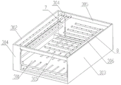
Fig. 2 is a schematic structural view of the embodiment of the present invention without a closing mechanism.
Fig. 3 is a schematic structural diagram of a chassis according to an embodiment of the present invention.
Fig. 4 is a schematic structural view of the embodiment of the present invention without a closing mechanism.
Fig. 5 is a partially enlarged view of a portion a in fig. 4.
Fig. 6 is a schematic structural view of the embodiment of the present invention without a closing mechanism.
Fig. 7 is a partially enlarged view of a portion B in fig. 6.
FIG. 8 is a schematic structural diagram of a backwashing mechanism in an embodiment of the present invention.
FIG. 9 is a schematic top view of a back washing mechanism according to an embodiment of the present invention.
Fig. 10 is a partially enlarged view of a portion C in fig. 9.
FIG. 11 is a schematic front view of the back washing mechanism in the embodiment of the present invention.
FIG. 12 is a schematic top view of a back washing mechanism according to an embodiment of the present invention.
Fig. 13 is a schematic structural diagram of a chassis roller brush cleaning assembly according to an embodiment of the present invention.
Fig. 14 is a schematic structural diagram of a chassis roller brush cleaning assembly according to an embodiment of the present invention.
FIG. 15 is a schematic structural diagram of a use state of the embodiment of the present invention.
Fig. 16 is a partially enlarged view of a portion D in fig. 15.
Wherein the reference numerals are: 1. a ground surface; 2. a carrier plate; 3. a chassis; 301. a base plate; 302. a left side plate; 303. a right side plate; 304. a first mounting vertical plate; 305. a cross bar; 306. an inner horizontal plate; 4. a sealing mechanism; 401. a rectangular sleeve; 402. a closing plate; 403. a fourth drive motor; 404. a drive rack; 405. a rectangular notch; 406. a second driving gear; 407. a U-shaped chute; 5. a cleaning mechanism; 6. a chassis roller brush cleaning assembly; 7. a left spray pipe fitting; 8. a right spray pipe fitting; 9. a first drive motor; 901. a first lead screw; 902. a first lead screw slide block; 903. installing a sliding block; 10. a bottom plate cleaning assembly; 11. a horizontal mounting rack; 1101. a horizontal stay bar; 1102. a middle supporting plate; 1103. a distal strut plate; 1104. a sliding sleeve; 1105. a mounting seat; 12. a chassis rolling brush; 13. a second drive motor; 1301. a second lead screw; 1302. a second lead screw slide block; 14. a front concave mounting plate; 15. a first U-shaped bracket; 16. a first connecting plate; 17. a bearing seat; 18. pushing the electric cylinder; 19. a rear concave mounting plate; 1901. limiting the inserting cylinder; 20. a second U-shaped bracket; 21. a second connecting plate; 2101. inserting a rod; 22. a roller brush drive motor; 23. a stationary semi-annular housing; 24. a sliding semi-annular housing; 25. a first semi-annular rotating plate; 26. a second semi-annular rotating plate; 27. a first outer annular half ring gear; 28. a second outer annular semi-ring gear; 29. a first rotating shaft; 30. rolling and brushing; 31. installing a side plate; 32. an inner gear ring drives the motor; 33. driving the full gear; 34. a U-shaped mounting bracket; 35. a second rotating shaft; 36. a first drive gear; 37. a first bevel gear; 38. a second bevel gear; 39. a fourth bevel gear; 40. a third bevel gear; 41. a third rotating shaft; 42. a third drive motor; 43. a third screw rod; 44. a third screw slide block; 45. a transverse connecting rod; 46. a bull's eye wheel; 47. a first inner annular half ring gear; 48. a second inner annular half gear ring; 49. and (4) cleaning the rod.
Detailed Description
In order to clearly illustrate the technical features of the present solution, the present solution is explained below by way of specific embodiments.
Referring to fig. 1-16, a movable vehicle washing chassis device comprises an underframe 3, a washing mechanism 5 and a back washing mechanism 5 which are arranged on the underframe 3, and further comprises a sealing mechanism 4 which is arranged on two sides of the underframe 3;
the cleaning mechanism 5 can clean the central area of the automobile chassis;
the ground 1 is provided with an installation pit position capable of supporting the chassis 3, meanwhile, the ground 1 on two sides of the chassis 3 is provided with a side installation pit position capable of accommodating the sealing mechanism 4, furthermore, bearing plates 2 are arranged on two sides of the chassis 3 and above the sealing mechanism 4, two ends of each bearing plate 2 are fixedly arranged on the bottom surface, and a vehicle is parked on the bearing plates 2 during cleaning;
preferably, drainage channels are pre-arranged in the installation pit position and the side installation pit position;
the underframe 3 comprises a bottom plate 301, a left side plate 302 and a right side plate 303, a pair of first mounting vertical plates 304 are symmetrically arranged on the inner sides of two ends of the left side plate 302, a first driving motor 9 is arranged on the inner side of the first mounting vertical plate 304 on one side, a first lead screw 901 is arranged at the end part of a motor shaft of the first driving motor 9, the end part of the first lead screw 901 is arranged on the first mounting vertical plate 304 on the other side, a plurality of first lead screw sliders 902 are arranged on the periphery of the first lead screw 901, mounting sliders 903 are arranged on the side surfaces of the first lead screw sliders 902, and a reverse cleaning mechanism 5 is arranged on the side surface of each mounting slider 903;
the cleaning mechanism 5 comprises second driving motors 13 which are arranged on the inner sides of the first mounting vertical plates 304 on the two sides and on the front side and the rear side of the bottom plate 301, second lead screws 1301 are arranged at the end parts of motor shafts of the second driving motors 13, second lead screw sliders 1302 are arranged on the peripheries of the second lead screws 1301 on the two sides, front concave mounting plates 14 and rear concave mounting plates 19 are respectively vertically arranged on the second lead screw sliders 1302 on the two sides, and chassis rolling brushes 3012 are arranged between the front concave mounting plates 14 and the rear concave mounting plates 19;
preferably, a guide rod is arranged between the left side plate 302 and the right side plate 303, and the second lead screw slider 1302 is arranged on the periphery of the guide rod;
the reverse cleaning mechanism 5 comprises a horizontal mounting rack 11 arranged on the side surface of the mounting slide block 903, and a chassis rolling brush cleaning component 6 and a bottom plate cleaning component 10 are arranged on the horizontal mounting rack 11;
the chassis rolling brush cleaning assembly 6 can clean the chassis rolling brush 3012, and the bottom plate cleaning assembly 10 can brush the bottom plate 301 to prevent the water leakage hole of the bottom plate 301 from being blocked.
A supporting cross rod 305 is arranged between the top side surfaces of the first installation vertical plates 304 and the right side plate 303, an inner horizontal plate 306 is arranged on the inner side of the right side plate 303, a right cleaning pipe is arranged on the inner horizontal plate 306, the right cleaning pipe is composed of a plurality of first cleaning pipes, and the first cleaning pipes are arranged in parallel with the supporting cross rod 305;
a left cleaning pipe fitting is arranged between the first mounting vertical plate 304 and the supporting cross rod 305 close to one side and two sides of the left side plate 302, the left cleaning pipe fitting is composed of a plurality of second cleaning pipes, the second cleaning pipes are arranged in parallel with the left side plate 302, and a gap for a chassis rolling brush 3012 to penetrate is arranged between the right cleaning pipe fitting and the left cleaning pipe fitting;
preferably, the right cleaning tube is positioned so as not to impede the movement of the front concave mounting plate 14 and the rear concave mounting plate 19.
A pair of pushing electric cylinders 18 are arranged on the outer side of the front concave mounting plate 14, first U-shaped brackets 15 are arranged at the end parts of electric push rods of the pushing electric cylinders 18, first connecting plates 16 are symmetrically arranged on two sides of the port of each first U-shaped bracket 15, the pair of pushing electric cylinders 18 are arranged on two sides of each first U-shaped bracket 15, and the end parts of the electric push rods of the pair of pushing electric cylinders 18 are respectively arranged on the first connecting plates 16 on the two sides;
a second U-shaped bracket 20 is movably arranged on the outer side of the rear concave mounting plate 19, second connecting plates 21 are symmetrically arranged on two sides of a port of the second U-shaped bracket 20, inserting rods 2101 are arranged on the bottom surfaces of the second connecting plates 21 on the two sides, a limiting inserting cylinder 1901 is arranged on the outer side of the rear concave mounting plate 19 corresponding to the inserting rods 2101, and the inserting rods 2101 are arranged in the limiting inserting cylinder 1901;
one end of a rotating shaft of the chassis rolling brush 3012 penetrates through a notch of the front concave mounting plate 14 and is arranged on the first U-shaped bracket 15 through a bearing seat 17, a rolling brush 30 driving motor 22 is arranged on the second U-shaped bracket 20, and the other end of the rotating shaft of the chassis rolling brush 3012 penetrates through a notch of the rear concave mounting plate 19 and is arranged on a motor shaft of the rolling brush 30 driving motor 22.
The chassis rolling brush cleaning assembly 6 comprises a pair of fixed semi-annular shells 23 arranged above the horizontal stay 1101 and on the side surface of the mounting plate, sliding sleeves 1104 are arranged on the peripheries of the horizontal stay 1101, and sliding semi-annular shells 24 corresponding to the fixed semi-annular shells 23 are arranged on the sliding sleeves 1104 on the two sides;
the fixed semi-annular shell 23 and the sliding semi-annular shell 24 both comprise a pair of semi-annular plates, a fixed column is arranged between the peripheral edge positions of the pair of semi-annular plates, a plurality of bull-eye wheels 46 are arranged on the inner sides of the semi-annular plates of the fixed semi-annular shell 23 and the sliding semi-annular shell 24, a first inner annular semi-gear ring 47 is arranged between the bull-eye wheels 46 on both sides in the fixed semi-annular shell 23, a second inner annular semi-gear ring 48 which is identical to the first inner annular semi-gear ring 47 is arranged between the bull-eye wheels 46 on both sides in the sliding semi-annular shell 24, a mounting side plate 31 is arranged on the side surfaces of the fixed semi-annular shell 23 and the sliding semi-annular shell 24, an inner gear ring driving motor 32 is arranged on the mounting side plate 31, and the motor shaft end parts of the inner gear driving motors 32 on both sides are respectively provided with the first inner annular semi-gear ring 47, a drive full gear 33 meshed with the second inner ring half-ring gear 48;
a first semi-annular rotating plate 25 is arranged between the first inner annular semi-gear rings 47 on the two sides, a second semi-annular rotating plate 26 is arranged between the second inner annular semi-gear rings 48 on the two sides, and the first semi-annular rotating plate 25 and the second semi-annular rotating plate 26 are respectively arranged on the inner sides of the fixed semi-annular shell 23 and the sliding semi-annular shell 24;
the mounting plate is provided with a third driving motor 42, the end part of a motor shaft of the third driving motor 42 is provided with a third screw rod 43, the end part of the third screw rod 43 is arranged on the middle supporting plate 1102, a transverse connecting rod 45 is arranged between the sliding sleeves 1104 on the two sides, a third screw rod sliding block 44 is arranged on the transverse connecting rod 45, and the third screw rod sliding block 44 is arranged on the periphery of the third screw rod 43.
A plurality of cleaning rods 49 are arranged on the inner sides of the first semi-annular rotating plate 25 and the second semi-annular rotating plate 26, and a plurality of water leakage holes are formed in the first semi-annular rotating plate 25 and the second semi-annular rotating plate 26;
the bottom plate cleaning assembly 10 comprises a pair of mounting seats 1105 arranged at the bottoms of the mounting plate, the far-end supporting plate 1103 and the middle supporting plate 1102, a first rotating shaft 29 is arranged in the mounting seat 1105 corresponding to the bottoms of the mounting plate, the far-end supporting plate 1103 and the middle supporting plate 1102, rolling brushes 30 are arranged between the mounting plate and the middle supporting plate 1102, between the middle supporting plate 1102 and the far-end supporting plate 1103, the rolling brushes 30 are arranged at the periphery of the first rotating shaft 29, and the rolling brushes 30 are arranged close to the surface of the bottom plate 301;
the outer surface of the first semi-annular rotating plate 25 is provided with a pair of first outer semi-ring gears 27, and the outer surface of the second semi-annular rotating plate 26 is provided with a pair of second outer semi-ring gears 28 which are identical with the first outer semi-ring gears 27 and correspond to the first outer semi-ring gears 27 in position;
a pair of U-shaped mounting frames 34 are arranged on the side surfaces of the mounting plates corresponding to the positions of the first outer annular half gear ring 27, a first driving gear 36 meshed with the first outer annular half gear ring 27 is arranged in each U-shaped mounting frame 34 through a second rotating shaft 35, the end part of each second rotating shaft 35 penetrates through the corresponding U-shaped mounting frame 34 to be provided with a first bevel gear 37, a third rotating shaft 41 is arranged on one side of each U-shaped mounting frame 34 and the mounting plates through supports, a second bevel gear 38 meshed with the first bevel gear 37 is arranged at the top end of the corresponding third rotating shaft 41, a third bevel gear 40 is arranged at the bottom end of the corresponding third rotating shaft 41, and a fourth bevel gear 39 meshed with the third bevel gear 40 is arranged on each first rotating shaft 29;
preferably, the outer sides of the fixed semi-annular shells 23 on the two sides are both provided with arc-shaped water spraying pipes, the arc-shaped water spraying pipes are provided with a plurality of water spraying holes, and the arc-shaped water spraying pipes are connected to a high-pressure water source through hoses;
when the corresponding fixed semi-annular housing 23 and the sliding semi-annular housing 24 are integrated, the fixed semi-annular housing 23 and the sliding semi-annular housing 24 form a complete annular housing, the first inner annular semi-ring 47 and the second inner annular semi-ring 48 form a complete annular ring, the first outer annular semi-ring 27 and the second outer annular semi-ring 28 form a complete annular ring, the driving full gear 33 can drive the annular ring formed by the first inner annular semi-ring 47 and the second inner annular semi-ring 48 to rotate, at the same time, the first semi-annular rotating plate 25 and the second semi-annular rotating plate 26 can rotate, when the first semi-annular rotating plate 25 and the second semi-annular rotating plate 26 rotate, the first outer annular semi-ring 27 and the second outer annular semi-ring 28 form an annular ring which can drive the first driving gear 36 to rotate, and then through the transmission of the first bevel gear 37, the first bevel gear 37 and the first bevel gear 37, the first rotating shaft 29 rotates, so that the rolling brush 30 rotates to clean the water leakage holes of the bottom plate 301;
in the initial state, the fixed semi-annular shell 23 and the sliding semi-annular shell 24 are in a separated state, and the chassis rolling brush 3012 is located right below a gap between the right cleaning pipe fitting and the left cleaning pipe fitting;
the central positions of the chassis roll brush 3012, the fixed semi-annular housing 23, and the sliding semi-annular housing 24 are on the same horizontal line.
The sealing mechanism 4 comprises rectangular sleeves 401 arranged on the ground 1 on two sides of the underframe 3, one ends of the rectangular sleeves 401 close to the underframe 3 are open, and the other ends of the underframe 3 are sealed;
a sealing plate 402 is arranged in each of the rectangular sleeves 401 at two sides, U-shaped sliding grooves 407 are arranged on the cross bars 305 at two sides and the first mounting vertical plates 304, one end of the sealing plate 402 is arranged in the rectangular sleeve 401, the other end of the sealing plate 402 is arranged in the U-shaped sliding groove 407, a rectangular notch 405 is formed in the side face of one side of each of the rectangular sleeves 401, a driving rack 404 is arranged on the side face of the sealing plate 402, the driving rack 404 is arranged in the rectangular notch 405, a fourth driving motor 403 is arranged on the side face of the open end of each of the rectangular sleeves 401, a second driving gear 406 matched with the driving rack 404 is arranged at the end part of a motor shaft of the fourth driving motor 403, and the driving gear is arranged in the rectangular notch 405;
the fourth driving motors 403 on both sides work synchronously and drive the driving gears to rotate, and the closing plates 402 on both sides are opened and closed through the cooperation of the driving gears and the driving racks 404.
A pair of first limiting guide rods is arranged between the upper side plate, the lower side plate and the two side plates of the first screw 901, and the installation sliding block 903 is arranged on the periphery of the first limiting guide rods.
When the vehicle is cleaned, the vehicle is kept still for a period of time, the chassis of the vehicle is cooled, the vehicle is parked on the bearing plates 2 on the two sides, the fourth driving motors 403 on the two sides work synchronously and drive the driving gears to rotate, and the sealing plates 402 on the two sides are opened through the matching of the driving gears and the driving racks 404;
the pushing electric cylinder 18 pushes up the chassis rolling brush 3012 to make the chassis rolling brush 3012 close to the chassis of the vehicle, the chassis rolling brush 3012 passes through the gap between the right cleaning pipe and the left cleaning pipe and is higher than the right cleaning pipe and the left cleaning pipe, then the second driving motor 13 drives the second screw 1301 to rotate forward and backward, the front concave mounting plate 14 and the rear concave mounting plate 19 move left and right (in the initial state, the chassis rolling brush 3012 is right below the gap between the right cleaning pipe and the left cleaning pipe, the chassis rolling brush 3012 first moves to one side of the right side plate 303, then the second driving motor 13 drives the second screw 1301 to rotate backward, the chassis rolling brush 3012 moves to one side of the left side plate 302, when the chassis rolling brush 3012 moves to the initial position, the second driving motor 13 drives the second screw 1301 to rotate backward again, the chassis rolling brush 3012 again moves to one side of the right side plate 303, so in the past, the front concave mounting plate 14 and the rear concave mounting plate 19 move left and right), the roller brush 30 drives the chassis roller brush 3012 to rotate to clean the chassis of the automobile, the high-pressure water source of the left spray pipe fitting 7 and the right spray pipe fitting 8 is opened to clean the chassis (preferably, the water inlet ends of the left spray pipe fitting 7 and the right spray pipe fitting 8 are connected to the high-pressure water source), the second driving motor 13 drives the front concave mounting plate 14 and the rear concave mounting plate 19 to reset after the cleaning is finished, then the electric cylinder 18 is pushed to drive the chassis rolling brush 3012 to reset, the chassis rolling brush 3012 is positioned right below the gap between the right cleaning pipe fitting and the left cleaning pipe fitting after resetting, finally the fourth driving motors 403 on both sides work synchronously and drive the driving gear to rotate, through the matching of the driving gear and the driving rack 404, the closing plates 402 on the two sides are closed, and the vehicle is driven away after the closing to finish the cleaning;
when the bottom plate 301 and the chassis rolling brush 3012 need to be cleaned, the two side closing plates 402 are closed, the second driving motor 13 drives the second screw 1301 to rotate, the second screw 1301 drives the front concave mounting plate 14 and the rear concave left side plate 302 to move, the chassis rolling brush 3012 enters the fixed semi-annular shell 23, when the chassis rolling brush 3012 is overlapped with the central position of the fixed semi-annular shell 23, the second driving motor 13 stops working (the distance that the chassis rolling brush 3012 enters the fixed semi-annular shell 23 to move is fixed, the second screw 1301 drives the front concave mounting plate 14 and the rear concave left side plate 302 to move by a fixed distance), the third driving motor 42 drives the transverse connecting rod 45 to move, when the fixed semi-annular shell 23 and the sliding semi-annular shell 24 are integrated, the third driving motor 42 stops working, and then the first driving motor 9 drives the first screw 901 to rotate, the mounting slide 903 moves back and forth, while moving, the full gear 33 is driven to rotate so as to drive the annular gear ring formed by the first inner annular half gear ring 47 and the second inner annular half gear ring 48 to rotate, the first semi-annular rotating plate 25 and the second semi-annular rotating plate 26 can rotate, when the first semi-annular rotating plate 25 and the second semi-annular rotating plate 26 rotate, the annular gear ring formed by the first outer annular half gear ring 27 and the second outer annular half gear ring 28 can drive the first driving gear 36 to rotate, then the first rotating shaft 29 rotates through the transmission of the first bevel gear 37, the second bevel gear 38, the third bevel gear 40 and the fourth bevel gear 39, so that the rolling brush 30 rotates to clean the water leakage holes of the bottom plate 301, meanwhile, high-pressure water sources of the left spraying pipe fitting 7, the right spraying pipe fitting 8 and the arc-shaped spraying pipe fitting are all opened, water of the left spraying pipe fitting 7 and the right spraying pipe fitting 8 passes through the blocking of the blocking plate 402, the water flows to the bottom plate 301, the rolling brush 30 rotates to clean water leakage holes of the bottom plate 301, the arc-shaped water spray pipe washes the chassis pipe brush (in the washing process, the pipe brush driving motor drives the chassis rolling brush 3012 to rotate to realize bidirectional cleaning), and the first semi-annular rotating plate 25 and the second semi-annular rotating plate 26 rotate to clean the chassis rolling brush 3012 through the cleaning rod 49;
after the cleaning is finished, the high-pressure water source of the left spraying pipe fitting 7, the right spraying pipe fitting 8 and the arc-shaped spraying pipe is closed, the first driving motor 9 drives the installation sliding block 903 to reset, the third driving motor 42 drives the transverse connecting rod 45 to move, the sliding semi-annular shell 24 is far away from the fixed semi-annular shell 23, after the third driving motor 42 stops working, the second driving motor 13 drives the front concave mounting plate 14 and the rear concave mounting plate 19 to reset, the chassis rolling brush 3012 is located right below a gap between the right cleaning pipe fitting and the left cleaning pipe fitting after resetting, and the cleaning is finished.
The technical features of the present invention which are not described in the above embodiments may be implemented by or using the prior art, and are not described herein again, of course, the above description is not intended to limit the present invention, and the present invention is not limited to the above examples, and variations, modifications, additions or substitutions which may be made by those skilled in the art within the spirit and scope of the present invention should also fall within the protection scope of the present invention.
Claims (9)
1. A movable vehicle washing chassis device is characterized by comprising an underframe, a washing mechanism and a back washing mechanism which are arranged on the underframe, and sealing mechanisms arranged on two sides of the underframe;
the chassis comprises a bottom plate, a left side plate and a right side plate, a pair of first installation vertical plates are symmetrically arranged on the inner sides of two ends of the left side plate, a first driving motor is arranged on the inner side of one first installation vertical plate, a first lead screw is arranged at the end part of a motor shaft of the first driving motor, the end part of the first lead screw is arranged on the first installation vertical plate on the other side, a plurality of first lead screw sliding blocks are arranged on the periphery of the first lead screw, installation sliding blocks are arranged on the side surfaces of the plurality of first lead screw sliding blocks, and the anti-cleaning mechanism is arranged on the side surface of each installation sliding block;
the cleaning mechanism comprises second driving motors which are arranged on the inner sides of the first mounting vertical plates on two sides and on the front side and the rear side of the bottom plate, a second lead screw is arranged at the end part of a motor shaft of each second driving motor, second lead screw sliding blocks are arranged on the peripheries of the second lead screws on the two sides, a front concave mounting plate and a rear concave mounting plate are vertically arranged on the second lead screw sliding blocks on the two sides respectively, and a chassis rolling brush is arranged between the front concave mounting plate and the rear concave mounting plate;
the anti-cleaning mechanism comprises a horizontal mounting frame arranged on the side face of the mounting sliding block, and a chassis rolling brush cleaning assembly and a bottom plate cleaning assembly are arranged on the horizontal mounting frame.
2. The movable vehicle washing chassis device according to claim 1, wherein a supporting cross bar is arranged between the top side of each first mounting vertical plate and the right side plate, an inner horizontal plate is arranged on the inner side of the right side plate, a right cleaning pipe is arranged on the inner horizontal plate, the right cleaning pipe is composed of a plurality of first cleaning pipes, and the first cleaning pipes are arranged in parallel with the supporting cross bar;
be close to left side board one side, both sides first installation riser with it washs the pipe fitting to support to be provided with a left side between the horizontal pole, a left side is washd the pipe fitting and is managed by a plurality of second purgers, the second purger with left side board parallel arrangement, the right side wash the pipe fitting with a left side is washd and is provided with the confession between the pipe fitting the clearance that the chassis round brush passed.
3. The movable vehicle washing chassis device according to claim 2, wherein a pair of pushing electric cylinders are arranged outside the front concave mounting plate, a first U-shaped bracket is arranged at the end part of an electric push rod of each pushing electric cylinder, first connecting plates are symmetrically arranged on two sides of the port of each first U-shaped bracket, the pair of pushing electric cylinders are arranged on two sides of the first U-shaped bracket, and the end parts of the electric push rods of the pair of pushing electric cylinders are respectively arranged on the first connecting plates on two sides;
a second U-shaped bracket is movably arranged on the outer side of the rear concave mounting plate, second connecting plates are symmetrically arranged on two sides of a port of the second U-shaped bracket, inserting rods are arranged on the bottom surfaces of the second connecting plates on two sides, a limiting inserting cylinder is arranged on the outer side of the rear concave mounting plate corresponding to the inserting rods, and the inserting rods are arranged in the limiting inserting cylinder;
one end of a rotating shaft of the chassis rolling brush penetrates through the notch of the front concave mounting plate and is arranged on the first U-shaped support frame through a bearing seat, a rolling brush driving motor is arranged on the second U-shaped support frame, and the other end of the rotating shaft of the chassis rolling brush penetrates through the notch of the rear concave mounting plate and is arranged on a motor shaft of the rolling brush driving motor.
4. The movable car washing chassis device according to claim 1, wherein the horizontal mounting frame comprises a mounting plate arranged on the side of the mounting slider, a pair of parallel horizontal support rods are arranged on the side of the mounting plate close to the bottom, a pair of the horizontal support rods are far away from the end part of one end of the mounting plate and provided with a far-end supporting plate, a middle supporting plate is arranged between the far-end supporting plate and the mounting plate and on the horizontal support rods, the mounting plate is flush with the bottom surface of the middle supporting plate, and the bottom surfaces of the middle supporting plate and the far-end supporting plate are provided with supporting wheels.
5. The movable vehicle washing chassis device according to claim 4, wherein the chassis rolling brush cleaning assembly comprises a pair of fixed semi-annular shells arranged above the horizontal support rods and at the side of the mounting plate, sliding sleeves are arranged on the peripheries of the horizontal support rods, and sliding semi-annular shells corresponding to the fixed semi-annular shells are arranged on the sliding sleeves at two sides;
the fixed semi-annular shell and the sliding semi-annular shell both comprise a pair of semi-annular plates, a fixed column is arranged between the peripheral edge positions of the pair of semi-annular plates, the inner sides of the semi-annular plates of the fixed semi-annular shell and the sliding semi-annular shell are both provided with a plurality of bull-eye wheels, a first inner annular semi-gear ring is arranged between the bull-eye wheels at two sides in the fixed semi-annular shell, a second inner annular semi-gear ring which is identical to the first inner annular semi-gear ring is arranged between the bull-eye wheels at two sides in the sliding semi-annular shell, mounting side plates are arranged on the fixed semi-annular shell and the side surface of the sliding semi-annular shell at one side, an inner gear ring driving motor is arranged on the mounting side plate, and driving full gears meshed with the first inner annular half gear ring and the second inner annular half gear ring are respectively arranged at the motor shaft end parts of the inner gear ring driving motors on the two sides;
a first semi-annular rotating plate is arranged between the first inner annular semi-gear rings on two sides, a second semi-annular rotating plate is arranged between the second inner annular semi-gear rings on two sides, and the first semi-annular rotating plate and the second semi-annular rotating plate are respectively arranged on the inner sides of the fixed semi-annular shell and the sliding semi-annular shell;
be provided with third driving motor on the mounting panel, third driving motor's motor shaft tip is provided with the third lead screw, third lead screw tip sets up on the middle section fagging, both sides be provided with the transverse connection pole between the sliding sleeve, be provided with the third lead screw slider on the transverse connection pole, the setting of third lead screw slider is in the third lead screw is peripheral.
6. The movable vehicle washing chassis device according to claim 5, wherein a plurality of cleaning rods are arranged on the inner sides of the first semi-annular rotating plate and the second semi-annular rotating plate, and a plurality of water leakage holes are formed in the first semi-annular rotating plate and the second semi-annular rotating plate.
7. The movable vehicle washing chassis device according to claim 6, wherein the bottom plate cleaning assembly comprises a pair of mounting seats arranged at the bottoms of the mounting plate, the far-end supporting plate and the middle supporting plate, a first rotating shaft is arranged in the mounting seat corresponding to the bottoms of the mounting plate, the far-end supporting plate and the middle supporting plate, rolling brushes are arranged between the mounting plate and the middle supporting plate and between the middle supporting plate and the far-end supporting plate, the rolling brushes are arranged at the periphery of the first rotating shaft, and the rolling brushes are arranged close to the surface of the bottom plate;
the outer surface of the first semi-annular rotating plate is provided with a pair of first outer semi-ring gears, and the outer surface of the second semi-annular rotating plate is provided with a pair of second outer semi-ring gears which are identical to the first outer semi-ring gears and correspond to the first outer semi-ring gears in position;
the mounting panel side corresponds first outer annular half ring gear position is provided with a pair of U-shaped mounting bracket, be provided with through the second pivot in the U-shaped mounting bracket with the first driving gear of first outer annular half ring gear meshing, second pivot tip is worn out the U-shaped mounting bracket is provided with first bevel gear, U-shaped mounting bracket one side be provided with the third pivot through the support on the mounting panel, third pivot top be provided with the second bevel gear of first bevel gear meshing, third pivot bottom is provided with third bevel gear, be provided with in the first pivot with the fourth bevel gear of third bevel gear meshing.
8. The movable vehicle washing chassis device according to claim 2, wherein the closing mechanism comprises a rectangular sleeve disposed on the ground on both sides of the bottom frame, one end of the rectangular sleeve adjacent to the bottom frame is open, and the other end of the bottom frame is closed;
the two sides are respectively provided with a sealing plate in the rectangular sleeve, the two sides are respectively provided with a U-shaped sliding groove on the cross rod and the first installation vertical plate, one end of the sealing plate is arranged in the rectangular sleeve, the other end of the sealing plate is arranged in the U-shaped sliding groove, a rectangular notch is formed in one side face of the rectangular sleeve, a driving rack is arranged on the side face of the sealing plate, the driving rack is arranged in the rectangular notch, a fourth driving motor is arranged on the side face of the open end of the rectangular sleeve, the end portion of a motor shaft of the fourth driving motor is provided with a second driving gear matched with the driving rack for use, and the driving gear is arranged in the rectangular notch.
9. The movable vehicle washing chassis device according to claim 1, wherein a pair of first limiting guide rods are arranged between the side plates on the upper side and the lower side of the first screw rod and between the side plates on the two sides, and the mounting sliding block is arranged on the periphery of the first limiting guide rods.
Priority Applications (2)
| Application Number | Priority Date | Filing Date | Title |
|---|---|---|---|
| CN202111546865.4A CN114228668B (en) | 2021-12-16 | 2021-12-16 | Movable vehicle washing chassis device |
| CN202311758844.8A CN117622067A (en) | 2021-12-16 | 2021-12-16 | Automobile chassis cleaning device |
Applications Claiming Priority (1)
| Application Number | Priority Date | Filing Date | Title |
|---|---|---|---|
| CN202111546865.4A CN114228668B (en) | 2021-12-16 | 2021-12-16 | Movable vehicle washing chassis device |
Related Child Applications (1)
| Application Number | Title | Priority Date | Filing Date |
|---|---|---|---|
| CN202311758844.8A Division CN117622067A (en) | 2021-12-16 | 2021-12-16 | Automobile chassis cleaning device |
Publications (2)
| Publication Number | Publication Date |
|---|---|
| CN114228668A true CN114228668A (en) | 2022-03-25 |
| CN114228668B CN114228668B (en) | 2023-12-22 |
Family
ID=80757487
Family Applications (2)
| Application Number | Title | Priority Date | Filing Date |
|---|---|---|---|
| CN202311758844.8A Pending CN117622067A (en) | 2021-12-16 | 2021-12-16 | Automobile chassis cleaning device |
| CN202111546865.4A Active CN114228668B (en) | 2021-12-16 | 2021-12-16 | Movable vehicle washing chassis device |
Family Applications Before (1)
| Application Number | Title | Priority Date | Filing Date |
|---|---|---|---|
| CN202311758844.8A Pending CN117622067A (en) | 2021-12-16 | 2021-12-16 | Automobile chassis cleaning device |
Country Status (1)
| Country | Link |
|---|---|
| CN (2) | CN117622067A (en) |
Citations (12)
| Publication number | Priority date | Publication date | Assignee | Title |
|---|---|---|---|---|
| CN105946810A (en) * | 2016-07-27 | 2016-09-21 | 东莞市赛力自动化设备科技股份有限公司 | Self-cleaning rolling brush for car washing |
| CN106347321A (en) * | 2016-10-08 | 2017-01-25 | 徐慈军 | Micro-water self-cleaning vehicle cleaning device |
| CN106828434A (en) * | 2017-03-31 | 2017-06-13 | 黄石劲平源科技有限公司 | A kind of domestic intelligent vehicle-washing device |
| CN107719322A (en) * | 2017-11-01 | 2018-02-23 | 太仓麦迪斯自动化设备有限公司 | A kind of automatic cleaning platform of vehicle bottom |
| US20190054901A1 (en) * | 2017-08-21 | 2019-02-21 | Matthews Tire, Inc. | Wheel cleaning system |
| CN208630566U (en) * | 2018-06-19 | 2019-03-22 | 济南睿达汽车服务有限公司 | A kind of automobile spraying and cleaning apparatus |
| CN111072172A (en) * | 2019-12-17 | 2020-04-28 | 阜阳师范大学 | Automatic car washer sewage cycle treatment device |
| CN111248644A (en) * | 2020-01-10 | 2020-06-09 | 江苏华梁智能制造有限公司 | Intelligent self-cleaning wardrobe |
| CN112644431A (en) * | 2020-09-02 | 2021-04-13 | 宁波猎知乐科技咨询有限公司 | Car chassis flushing device for automobile beauty |
| CN112842140A (en) * | 2019-11-27 | 2021-05-28 | 珠海市一微半导体有限公司 | Self-cleaning robot with self-cleaning rolling brush and intelligent self-cleaning robot |
| CN113306529A (en) * | 2021-07-15 | 2021-08-27 | 深圳市益铭汽车美容有限公司 | Car chassis rapid flushing equipment for automobile beauty |
| CN216580453U (en) * | 2021-12-16 | 2022-05-24 | 张家港睿达智能装备有限公司 | Automobile chassis cleaning device |
-
2021
- 2021-12-16 CN CN202311758844.8A patent/CN117622067A/en active Pending
- 2021-12-16 CN CN202111546865.4A patent/CN114228668B/en active Active
Patent Citations (12)
| Publication number | Priority date | Publication date | Assignee | Title |
|---|---|---|---|---|
| CN105946810A (en) * | 2016-07-27 | 2016-09-21 | 东莞市赛力自动化设备科技股份有限公司 | Self-cleaning rolling brush for car washing |
| CN106347321A (en) * | 2016-10-08 | 2017-01-25 | 徐慈军 | Micro-water self-cleaning vehicle cleaning device |
| CN106828434A (en) * | 2017-03-31 | 2017-06-13 | 黄石劲平源科技有限公司 | A kind of domestic intelligent vehicle-washing device |
| US20190054901A1 (en) * | 2017-08-21 | 2019-02-21 | Matthews Tire, Inc. | Wheel cleaning system |
| CN107719322A (en) * | 2017-11-01 | 2018-02-23 | 太仓麦迪斯自动化设备有限公司 | A kind of automatic cleaning platform of vehicle bottom |
| CN208630566U (en) * | 2018-06-19 | 2019-03-22 | 济南睿达汽车服务有限公司 | A kind of automobile spraying and cleaning apparatus |
| CN112842140A (en) * | 2019-11-27 | 2021-05-28 | 珠海市一微半导体有限公司 | Self-cleaning robot with self-cleaning rolling brush and intelligent self-cleaning robot |
| CN111072172A (en) * | 2019-12-17 | 2020-04-28 | 阜阳师范大学 | Automatic car washer sewage cycle treatment device |
| CN111248644A (en) * | 2020-01-10 | 2020-06-09 | 江苏华梁智能制造有限公司 | Intelligent self-cleaning wardrobe |
| CN112644431A (en) * | 2020-09-02 | 2021-04-13 | 宁波猎知乐科技咨询有限公司 | Car chassis flushing device for automobile beauty |
| CN113306529A (en) * | 2021-07-15 | 2021-08-27 | 深圳市益铭汽车美容有限公司 | Car chassis rapid flushing equipment for automobile beauty |
| CN216580453U (en) * | 2021-12-16 | 2022-05-24 | 张家港睿达智能装备有限公司 | Automobile chassis cleaning device |
Also Published As
| Publication number | Publication date |
|---|---|
| CN117622067A (en) | 2024-03-01 |
| CN114228668B (en) | 2023-12-22 |
Similar Documents
| Publication | Publication Date | Title |
|---|---|---|
| CN108297839B (en) | Oscillating car side door belt cleaning device | |
| CN110788052A (en) | Plating device for metal material | |
| CN210396581U (en) | Aluminum alloy window with cleaning device | |
| KR100732996B1 (en) | Auto car washer for vehicle and car washing method therefor | |
| CN216580453U (en) | Automobile chassis cleaning device | |
| CN114228668A (en) | Movable vehicle washing chassis device | |
| CN113264013A (en) | Multifunctional maintenance device for automobile chassis | |
| US3599650A (en) | Car wash | |
| CN212190198U (en) | Belt cleaning device is used in automobile tire production | |
| CN112963662A (en) | Pipeline flaw detection robot | |
| CN112141054A (en) | Vehicle cleaning device that dispatches from factory for building construction site | |
| CN207617689U (en) | A kind of automatic car cleaning device | |
| CN115055457A (en) | Pipe piece cleaning device | |
| CN209505701U (en) | A kind of automobile is convenient for the shell cleaning device in adjusting orientation | |
| CN212943572U (en) | Automatic water spraying device | |
| CN114435311A (en) | Prewashing controllable temperature car washer protected in automobile body | |
| CN216034276U (en) | Water recycling type car washer for construction engineering | |
| CN212245105U (en) | Roller bed cleaning device for automobile production | |
| CN217124750U (en) | Automatic cleaning device for mining automobile tire | |
| CN219723811U (en) | Equipment maintenance vehicle with cleaning function | |
| CN216861410U (en) | Vehicle moving device for automatic car washer | |
| CN216685919U (en) | Carriage detachable garbage truck | |
| CN220789576U (en) | Municipal works road cleaning device | |
| CN214325059U (en) | Car washer shower nozzle steering mechanism | |
| CN113635869B (en) | Automatic conveying automobile cleaning device |
Legal Events
| Date | Code | Title | Description |
|---|---|---|---|
| PB01 | Publication | ||
| PB01 | Publication | ||
| SE01 | Entry into force of request for substantive examination | ||
| SE01 | Entry into force of request for substantive examination | ||
| GR01 | Patent grant | ||
| GR01 | Patent grant | ||
| TR01 | Transfer of patent right | ||
| TR01 | Transfer of patent right |
Effective date of registration: 20240204 Address after: Room 402, Unit 9, Building 25, No. 108 Huanshan Road, Lixia District, Jinan City, Shandong Province, 250000 Patentee after: Zhang Lili Country or region after: China Address before: 215634 No. 199, Hongwu Avenue, Tangqiao town, Zhangjiagang City, Suzhou City, Jiangsu Province Patentee before: Zhangjiagang Ruida Intelligent Equipment Co.,Ltd. Country or region before: China |