CN114228454B - Back door assembly - Google Patents
Back door assembly Download PDFInfo
- Publication number
- CN114228454B CN114228454B CN202111561441.5A CN202111561441A CN114228454B CN 114228454 B CN114228454 B CN 114228454B CN 202111561441 A CN202111561441 A CN 202111561441A CN 114228454 B CN114228454 B CN 114228454B
- Authority
- CN
- China
- Prior art keywords
- wall surface
- plate
- elastic buckle
- arm
- back door
- Prior art date
- Legal status (The legal status is an assumption and is not a legal conclusion. Google has not performed a legal analysis and makes no representation as to the accuracy of the status listed.)
- Active
Links
Images


Classifications
-
- B—PERFORMING OPERATIONS; TRANSPORTING
- B60—VEHICLES IN GENERAL
- B60J—WINDOWS, WINDSCREENS, NON-FIXED ROOFS, DOORS, OR SIMILAR DEVICES FOR VEHICLES; REMOVABLE EXTERNAL PROTECTIVE COVERINGS SPECIALLY ADAPTED FOR VEHICLES
- B60J5/00—Doors
- B60J5/10—Doors arranged at the vehicle rear
- B60J5/101—Doors arranged at the vehicle rear for non-load transporting vehicles, i.e. family cars including vans
- B60J5/107—Doors arranged at the vehicle rear for non-load transporting vehicles, i.e. family cars including vans constructional details, e.g. about door frame, panels, materials used, reinforcements
-
- B—PERFORMING OPERATIONS; TRANSPORTING
- B60—VEHICLES IN GENERAL
- B60R—VEHICLES, VEHICLE FITTINGS, OR VEHICLE PARTS, NOT OTHERWISE PROVIDED FOR
- B60R13/00—Elements for body-finishing, identifying, or decorating; Arrangements or adaptations for advertising purposes
- B60R13/02—Internal Trim mouldings ; Internal Ledges; Wall liners for passenger compartments; Roof liners
- B60R13/0237—Side or rear panels
- B60R13/0243—Doors
-
- Y—GENERAL TAGGING OF NEW TECHNOLOGICAL DEVELOPMENTS; GENERAL TAGGING OF CROSS-SECTIONAL TECHNOLOGIES SPANNING OVER SEVERAL SECTIONS OF THE IPC; TECHNICAL SUBJECTS COVERED BY FORMER USPC CROSS-REFERENCE ART COLLECTIONS [XRACs] AND DIGESTS
- Y02—TECHNOLOGIES OR APPLICATIONS FOR MITIGATION OR ADAPTATION AGAINST CLIMATE CHANGE
- Y02T—CLIMATE CHANGE MITIGATION TECHNOLOGIES RELATED TO TRANSPORTATION
- Y02T10/00—Road transport of goods or passengers
- Y02T10/10—Internal combustion engine [ICE] based vehicles
- Y02T10/40—Engine management systems
Abstract
The invention relates to the technical field of automobile spare and accessory parts, and discloses a back door assembly, which comprises an upper guard plate and a back door inner plate; the inner plate is provided with a plug hole and a limit groove; the upper guard plate includes: the body is buckled on the inner plate; the elastic buckle is provided with a pair of mirror images; the limiting columns are provided with a pair of mirror images, and are respectively positioned beside each elastic buckle. The elastic buckles are arranged on the upper guard plate, so that the installation direction of the elastic buckles can be adjusted to be consistent with other structures on the inner plate, and the interference problem of the installation of the upper guard plate is reduced. And meanwhile, the limiting columns are also arranged for limiting the displacement in the left-right direction, so that the lateral pressure of the elastic buckle caused by swing is reduced, meanwhile, the kinetic energy of left-right impact is absorbed as much as possible, the deformation condition of the left side and the right side of the upper guard plate is reduced, and the service life of the upper guard plate is prolonged. Meanwhile, the inclined plane of the limiting column can generate a guiding effect, and the accurate alignment like a common buckle is not needed, so that the installation difficulty is reduced.
Description
Technical Field
The application relates to the technical field of automobile spare and accessory parts, in particular to a back door assembly.
Background
The back door assembly is used as an assembly with complex structure and relatively independent structure in the whole vehicle body. The novel back door mainly comprises a right back door outer cover plate, a back door inner cover plate, a back door hinge reinforcing plate, a back door supporting rod reinforcing plate, a back door machine reinforcing plate, a back door outer handle reinforcing plate, back door glass, a back door supporting rod, a back door lock mechanism, a back door outer decoration piece, a back door inner decoration piece and a back door sealing adhesive tape. The accessories are numerous and the structure is complex. The structural design of the back door and the arrangement process of the accessories are numerous in factors, large in workload and high in requirements, and the problems of performance, cost, installation process, movement interference and the like of the back door accessories are required to be considered in addition to the functional requirements of the vehicle door.
Currently, most SUVs and two-compartment vehicles are provided with a back door that can be flipped up, typically with a window for rearward viewing. In many vehicles, a wire harness for controlling various functions such as automatic turning and signal transmission is also required to be installed on the back door. Therefore, in many vehicles, a back door guard needs to be provided on the back door to block the line inside the back door, and at the same time, collision and scratch of the back door sheet metal part can be prevented.
In the prior art, the traditional back door assembly is mainly divided into a back door outer plate assembly and a back door inner guard plate assembly, wherein the back door inner guard plate assembly is further divided into a back door upper guard plate, a back door left and right guard plate and a back door lower guard plate, and the main functions are attractive and comfort improvement. In the assembly process, the installation of the lower guard plate of the traditional back door needs to be positioned with the left guard plate and the right guard plate and needs to be positioned with the outer plate assembly of the back door, so that the installation steps are complex, the installation is difficult, the traditional back door guard plate and the outer plate assembly of the back door are connected by white nails, the white nails are easy to lose efficacy and are not firm in clamping in the later repeated disassembly and assembly process, and the stability of the structure is affected.
The back door guard board is generally covered around the window of the back door and is divided into an upper guard board, a lower guard board and a left side guard board and a right side guard board, wherein the upper guard board and the lower guard board have the effect of shielding sheet metal parts and circuits, and the left side guard board and the right side guard board basically only have the effect of supporting the upper guard board and being attractive in whole, and are quite redundant. However, some prior arts try to cancel the left and right side shields and find the effect not good, firstly, the left and right side shields are discarded, the upper shield needs to be extended to the left and right sides for fitting and positioning, and the normal direction of the boundary of the two sides of the upper shield is not the same as the traveling direction during installation, which results in that the direction of the fastener installation for the fixed side is actually different from the traveling direction during installation of the upper shield, so that the fastener installation for the fixed side is very difficult, and meanwhile, the side fastener also has interference problem with the protruding structure of the back door. Meanwhile, only the upper guard plate is used without the left guard plate and the right guard plate, so that the left side and the right side of the upper guard plate are easy to tilt.
Disclosure of Invention
To the defect that exists among the prior art, the aim at of this application provides a back door subassembly, can avoid interfering the problem, simple to operate simultaneously, can also alleviate the perk problem of backplate.
In order to achieve the above purpose, on one hand, the technical scheme adopted is as follows:
in the application, a back door assembly is provided, which comprises an upper guard plate and an inner plate of a back door;
the two ends of the upper wall surface of the inner plate are provided with plug holes, and limit grooves are respectively arranged between the upper wall surface and the left wall surface of the inner plate and between the upper wall surface and the right wall surface;
the upper guard plate includes:
the body is U-shaped and is buckled on the upper wall surface, part of the left wall surface and part of the right wall surface of the inner plate;
the elastic buckle is provided with a pair of mirror images, is respectively arranged at two corners of the U-shaped body and faces the inner plate; each elastic buckle is provided with two arms, wherein one arm extends to the direction opposite to the two arms to form barbs; when the elastic buckle is inserted into the insertion hole, the barb hooks the edge of the insertion hole;
the limiting columns are arranged in a mirror image mode, are located beside each elastic buckle respectively, extend out of the body towards the inner plate direction, and are matched with the limiting grooves.
Preferably, the elastic buckle comprises a first reinforcing rib, and the first reinforcing rib is installed on the opposite side surfaces of the two arms and the bottom surface between the two arms of the elastic buckle in a U shape.
Preferably, one arm of the elastic buckle, which is not provided with a barb, is divided into a vertical arm and an extending arm;
the vertical arm is arranged in parallel with one arm of the elastic buckle, which is provided with a barb;
the extending arm is perpendicular to the vertical arm in the direction away from the vertical arm, and the width of the extending arm gradually decreases from the root of the elastic buckle to the extending end;
when the elastic buckle is inserted into the insertion hole, one corner of the extending arm and one corner of the insertion hole are abutted against each other.
Preferably, the ends of the left wall surface and the right wall surface of the body are round edges.
Preferably, the left wall surface and the right wall surface of the body are adjacent to the tail end to form a convex part, and the convex part and the round edge are in smooth transition.
Preferably, the lower edge of the upper wall surface of the inner plate protrudes towards the body to form a lower abutting plate;
the lower edge of the body protrudes downwards to form a lower reinforcing rib;
the lower reinforcing rib and the lower retaining plate are mutually abutted and form zero-paste fit.
Preferably, the end face of the extending end of the lower reinforcing rib is an arc surface.
Preferably, the limit groove includes:
the outer baffle is formed by protruding towards the outside direction of the vehicle at the junction of the upper wall surface and the corresponding side wall surface of the inner plate;
and the inner clamping plate is formed by extending out of the intersection of the upper wall surfaces of the outer baffle plate and the inner plate into the vehicle, and the extending direction of the inner clamping plate faces the corresponding side surface of the inner plate.
Preferably, the limit column is inclined towards the direction of the inner clamping plate, and the end face of the extending end of the limit column is a smooth surface;
when the limit post is matched with the limit groove, the inner clamping plate stretches into an included angle between the limit post and the body.
Preferably, the extending end of the inner clamping plate bulges to form a sliding head, and the edge of the sliding head is smoothly arranged.
The beneficial effects that technical scheme that this application provided brought include:
the utility model provides a back door subassembly owing to be provided with the elasticity buckle that points to the back upper wall surface on the backplate on last backplate, can adjust the installation direction of elasticity buckle and other structures follow mutually on the backplate, has reduced the interference problem of last backplate installation, and the structure of two arms and the barb of establishing at one of them arm have played sufficient supporting role, have consequently avoided the buckle support of lateral wall. Meanwhile, the limiting columns are arranged, the limiting columns are mainly used for limiting displacement in the left-right direction, lateral pressure of elastic buckles caused by swing in the using process of the vehicle is reduced, meanwhile, kinetic energy of left-right impact is absorbed as much as possible, deformation of two sides of the upper guard plate is converted into change of relative angles between the limiting columns and the body, deformation conditions of the left side and the right side of the upper guard plate are reduced, and service life of the upper guard plate is prolonged. Meanwhile, the inclined plane of the limiting column can generate a guiding effect, so that the limiting column does not need to be aligned accurately like a buckle, the specific length is not needed, the length of the limiting column has larger selecting space, limiting columns with different lengths can be selected according to specific structures of side wall surfaces of inner plates of different vehicle types, protrusions which can interfere are avoided, and the mounting difficulty is reduced.
Simultaneously, utilize elasticity buckle and spacing post to connect, the position of main wearing and tearing is elasticity buckle and spacing post and the adjacent bottom surface on the backplate, when need change the backplate after long-term use, the damage of back door lining board is less than the backplate far away, consequently only change a new backplate can, prolonged the life of back door lining board, conveniently change back door subassembly. The problem that white nails are easy to lose efficacy in the later repeated disassembly and assembly process is avoided, and the clamping connection is firmer after long-term use compared with the prior art.
In some further improvements, the side face of the body is further provided with a smooth chamfer and a round angle, and the bottom face of the body is further provided with a smooth lower reinforcing rib, so that workers can be prevented from being cut in the transportation process.
Drawings
In order to more clearly illustrate the technical solutions of the embodiments of the present application, the drawings that are needed in the description of the embodiments will be briefly introduced below, and it is obvious that the drawings in the following description are only some embodiments of the present application, and that other drawings may be obtained according to these drawings without inventive effort for a person skilled in the art.
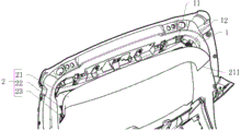
Fig. 1 is a schematic diagram of an embodiment of the present application when installed.
Fig. 2 is a schematic view of the junction between the upper wall surface and the left wall surface of the inner panel in the embodiment shown in fig. 1.
Fig. 3 isbase:Sub>A cross-sectional view atbase:Sub>A-base:Sub>A in fig. 2.
Fig. 4 is an enlarged view of fig. 3 at D.
Fig. 5 is a cross-sectional view at B-B in fig. 2.
Fig. 6 is a schematic structural diagram of the elastic buckle in the embodiment shown in fig. 1.
Fig. 7 is a schematic view of the structure of fig. 6 at another angle.
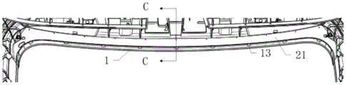
Fig. 8 is a front view of the embodiment shown in fig. 1.
Fig. 9 is a cross-sectional view of the body of fig. 8 taken along line C-C.
Reference numerals:
1. a back plate; 11. a plug hole; 12. a limit groove; 121. an outer baffle; 122. an inner clamping plate; 1221. a slider; 13. a lower retaining plate; 2. an upper guard board; 21. a body; 211. round edges; 212. a protruding portion; 213. a lower reinforcing rib; 22. elastic buckle; 221. a barb; 222. a first reinforcing rib; 223. a vertical arm; 224. a projecting arm; 23. and a limit column.
Detailed Description
In order to make the objects, technical solutions and advantages of the present application more apparent, the present invention will be further described in detail with reference to the accompanying drawings and examples. It should be understood that the specific embodiments described herein are for purposes of illustration only and are not intended to limit the scope of the invention. In addition, the technical features of the embodiments of the present invention described below may be combined with each other as long as they do not collide with each other.
In the present application, as shown in fig. 1, an embodiment of a back door assembly is provided, which includes a back door inner panel 1 and an upper guard 2 inserted into the back door inner panel 1.
The inner plate 1 is a plate of which the back door faces into a carriage, and is generally divided into four parts, namely an upper wall, a left wall, a right wall and a lower wall along the back door. In the present embodiment and the subsequent embodiments, the upper wall surface, the left wall surface, the right wall surface, and the lower wall surface of the inner panel 1 each refer to a surface of the upper wall, the left wall surface, the right wall surface, and the lower wall surface facing the inside of the vehicle body, and the upper wall surface, the left wall surface, the right wall surface, and the lower wall surface of the upper fender 2 each refer to a surface that is in contact with the upper wall surface, the left wall surface, the right wall surface, and the lower wall surface of the inner panel 1.
As shown in fig. 2, a pair of insertion holes 11 are provided on the upper wall surface of the inner panel 1, and a limit groove 12 is provided between the upper wall surface and the left wall surface of the inner panel 1 and between the upper wall surface and the right wall surface.
Correspondingly, the upper guard plate 2 comprises a body 21, an elastic buckle 22 and a limiting column 23.
The body 21 is approximately U-shaped, and is attached to the upper wall surface, part of the left wall surface and part of the right wall surface of the inner panel 1, and the surface close to the upper wall surface is the top surface of the body 21.
As shown in fig. 5, 6 and 7, the elastic buckle 22 has a pair of mirror images, and is respectively arranged at two corners of the U-shaped body 21 and faces the inner plate 1; each elastic buckle 22 has two arms, wherein one arm extends to the opposite direction of the two arms to form a barb 221; the elastic buckle 22 is matched with the plug hole 11, and when the elastic buckle 22 is plugged into the plug hole 11, the barb 221 hooks the edge of the plug hole 11. The barbs 221 of the elastic buckles 22 at the two sides push outwards towards each other, so that the elastic buckles 22 can be firmly clamped in the plug holes 11. In some embodiments, for the purpose of tight installation, the distance between the pair of elastic buckles 22 is generally set to be slightly larger than the corresponding plug hole 11, so that a slightly interference fit state is formed, when the pair of elastic buckles 22 are plugged, the two barbs 221 are opposite in direction, and the barbs 221 are tightly abutted in the plug hole 11 under the elastic action of the body 21 and the elastic buckles 22 together, so that the installation is tight.
As shown in fig. 7, a pair of limiting columns 23 are arranged in a mirror image manner and are respectively located beside each elastic buckle 22, each limiting column 23 extends out from the body 21 towards the direction of the inner plate 1, the limiting columns 23 are matched with the limiting grooves 12, the limiting columns 23 and the body 21 form a Y-shaped structure, the limiting grooves 12 are inserted into Y-shaped branches, so that the kinetic energy of left and right impact is absorbed as much as possible, and the deformation of two sides of the upper guard plate 2 is converted into the change of the relative angle between the limiting columns 23 and the body 21. Because the spacing post 23 only needs peg graft the lateral wall of spacing groove 12 in spacing post 23 and body 21 bifurcation department for there is very big margin in spacing post 23 length, and spacing effect is little to spacing length of post 23, consequently in the in-process of implementation, the designer can select the spacing post 23 of suitable length according to protruding and pencil equistructure etc. that set up on the left wall face of the interior board 1 of design and the right wall face to the arch and pencil of being convenient for bypass, very big reduction installation interference, and inclination does not have specific requirement yet between spacing post 23 and the body 21, so the installation of spacing post 23 is very convenient.
Specifically, when the installation of the embodiment is performed, the body 21 is lifted firstly, the two arms of the body 21 are aligned with the left wall surface and the right wall surface of the inner plate 1, then the body 21 is pushed upwards, meanwhile, the limiting column 23 is aligned with the limiting groove 12, finally, the limiting column 23 is inserted into the limiting groove 12, and the elastic buckle 22 is clamped in the inserting hole 11.
In some further embodiments, the resilient clip 22 further includes a first stiffener 222, and the first stiffener 222 is U-shaped and mounted on opposite sides of the two arms of the resilient clip 22 and on a bottom surface between the two arms. Specifically, the body 21 required by different vehicle types has a certain difference in weight, and when the preset weight of the body 21 is large, the general elastic buckle 22 does not necessarily have an effective supporting function, so in some embodiments, different first reinforcing ribs 222 may be provided according to needs to improve the elasticity of the elastic buckle 22, so that the elastic buckle can be adapted to the heavier body 21.
In some further arrangements, the arm of the resilient clip 22 where the barb 221 is not provided is divided into a vertical arm 223 and a protruding arm 224, and the vertical arm 223 is arranged in parallel with the arm of the resilient clip 22 where the barb 221 is provided.
The extending arm 224 is arranged perpendicular to the vertical arm 223 in a direction far away from the vertical arm 223, and the width of the extending arm 224 gradually decreases from the root of the elastic buckle 22 to the extending end.
When the elastic buckle 22 is inserted into the insertion hole 11, the protruding arm 224 is abutted against one corner of the insertion hole 11.
Specifically, the vertical arm 223 and the projecting arm 224 together form a generally L-shaped structure. In this way, the force may be applied by the gradually shrinking ramp of the extension arm 224 during installation, so that the extension arm 224 is smoother when inserted into the insertion hole 11.
In some preferred embodiments, as shown in fig. 4, the ends of the left wall surface and the right wall surface of the body 21 are rounded edges 211, and the rounded edges 211 can prevent the problem of cutting hands during the installation and transportation process, and can reduce the scratch of the surface of the inner board 1 caused by the body 21.
In the process of installing the body 21, not only the U-shaped top surface needs to be lifted in place, but also the two side edges need to be lifted by applying force.
Thus, in some more preferred embodiments, as shown in fig. 4, the left and right walls of the body 21 are formed with protrusions 212 adjacent to the ends, and the protrusions 212 smoothly transition with the rounded edges 211. The protruding portion 212 generally has a small protruding degree, and is basically invisible in appearance, and when the body 21 is pushed up, the protruding portion can play a role in supporting and generating force, meanwhile, the problem that the body 21 rebounds to clamp the hand is avoided, and the appearance between the body 21 and the inner plate 1 can be smoothly transited.
In a general embodiment, the installation is limited only by two elastic buckles 22, so that the body 21 is deformed in a long time due to severe jolt in the use process of the vehicle, and the service life is greatly shortened finally.
Thus, in some preferred embodiments, as shown in fig. 8 and 9, the lower edge of the upper wall surface of the inner board 1 protrudes toward the body 21 to form a lower retaining board 13; the lower edge of the body 21 protrudes downwards to form a lower reinforcing rib 213; the lower reinforcing rib 213 and the lower retaining plate 13 are abutted against each other and form a zero-fitting engagement.
Specifically, in a general case, the length of the lower reinforcing rib 213 is exactly zero-fitting, and in a specific practical process, the length of the lower reinforcing rib 213 can slightly exceed a preset length, so that under the limiting effect of the elastic buckle 22, a slight interference fit is formed between the lower reinforcing rib 213 and the lower retaining plate 13, the supporting effect of the lower retaining plate 13 is enhanced, meanwhile, the workload of the elastic buckle 22 can be reduced, and the service life of the back door assembly is prolonged.
In the installation process, a worker can hold the upper side and the lower side of the body 21 to prop the body 21 against the inner plate 1, the body 21 and the inner plate 1 are approximately aligned, the whole upper guard plate 2 is large in structure weight, the center is not easy to stabilize in the installation process, slipping and the like are frequently caused, and after the lower reinforcing ribs 213 are arranged, the lower reinforcing ribs 213 can also cause a hand cutting phenomenon in the process of transportation of the worker in the severe slipping process.
Thus, in some preferred embodiments, as shown in fig. 9, the end surface of the protruding end of the lower reinforcing rib 213 is an arc surface, and in some embodiments, it may be another surface such as a rounded rectangular surface close to the arc surface due to insufficient machining accuracy. Meanwhile, after the lower reinforcing ribs 213 are arranged into the arc surfaces, cutting damage to the lower retaining plate 13 is reduced, and the service life of the lower retaining plate 13 is prolonged. In some embodiments, in order to further reduce the risk of cutting the hand, an upper rib of the circular arc surface is provided at the upper edge of the body 21.
In some further embodiments, as shown in fig. 3, the limiting groove 12 includes an outer baffle 121 and an inner snap plate 122.
The specific configuration of the outer barrier 121 is determined by the position of the limiting groove 12, and for example, the left outer barrier 121 is formed by protruding the junction between the upper wall surface and the wall surface of the inner panel 1 in the vehicle outer direction. Specifically, the structure of the outer baffle 121 is close to a letter shape, and corners thereof are rounded to prevent the influence on the strength of the inner plate 1.
One end of the inner clamping plate 122 is connected to one side of the outer baffle 121 near the upper wall surface of the inner plate 1, and the other end extends toward the wall surface of the corresponding side of the inner plate 1, for example, the inner clamping plate 122 of the left limiting groove 12 extends toward the left wall surface of the inner plate 1. The inner clamping plate 122 is strip-shaped in the cross-sectional view, but in most embodiments the inner clamping plate 122 is a strip along the normal direction of the direction shown in the drawing, so that there is a certain sliding space between the limiting post 23 and the inner clamping plate 122.
When the inner plate 1 and the upper guard plate 2 are inserted, the inner clamping plate 122 extends into the included angle between the limiting post 23 and the body 21. The inner clamping plate 122 is a strip, and the limiting column 23 can slide on the inner clamping plate 122 to reach a preset installation position, so as to play a role of limiting.
Further, the protruding end of the inner clamping plate 122 is bulged to form a sliding head 1221, and the edge of the sliding head 1221 is smoothly arranged. The sliding head 1221 is arranged to effectively reduce the abrasion of the limit post 23 in the installation and use processes, and in addition, the vehicle can shake in the running process, so that the sliding head 1221 slides on the side surface of the limit post 23, which is close to the body 21, and the excessive shake is converted into impact to the root of the limit post 23, so that the impact force becomes pressure to the root of the limit post 23 as much as possible, rather than bending force to the limit post 23, and the service life of the limit post 23 is prolonged.
In summary, the structure of one embodiment in the present application is as follows:
the upper wall surface of the inner plate 1 is provided with a plug hole 11, a limit groove 12 is arranged between the upper wall surface and the left wall surface of the inner plate 1 and between the upper wall surface and the right wall surface, and the bottom surface of the inner plate 1 extends out of the lower retaining plate 13 towards the upper guard plate 2.
The limiting groove 12 of the inner plate 1 is divided into an outer baffle plate 121 and an inner clamping plate 122, and the outer baffle plate 121 is formed by extending the turning part of the inner plate 1 to the outside direction of the vehicle.
The upper guard plate 2 comprises a body 21, an elastic buckle 22 and a limiting column 23.
The body 21 is approximately U-shaped, and is attached to the upper wall surface, part of the left wall surface and part of the right wall surface of the inner plate 1, wherein the surface close to the upper wall surface is the top surface of the body 21, the bottom of the body 21 extends out of the lower reinforcing rib 213 towards the lower abutting plate 13, the bottom surface of the lower reinforcing rib 213 is an arc surface, the lower reinforcing rib 213 abuts against the lower abutting surface, and an upper reinforcing rib is also arranged at the upper end of the body 21 and is also in an arc shape, so that a worker is prevented from cutting his or her hands during carrying, but the upper reinforcing rib is not abutted against the inner plate 1.
The elastic buckle 22 is provided with a pair of mirror image settings, is respectively positioned at two corners of the U-shaped body 21 and is directed to the upper wall surface of the inner plate 1, the elastic buckle 22 is inserted into the insertion hole 11, each elastic buckle 22 is provided with two arms, the top end of one arm extends towards the opposite directions of the two arms to form a barb 221, one arm of the elastic buckle 22, which is not provided with the barb 221, is divided into a vertical arm 223 and an extending arm 224, and the vertical arm 223 and one arm of the elastic buckle 22, which are provided with the barb 221, are arranged in parallel. The extending arm 224 is arranged perpendicular to the vertical arm 223 in a direction far away from the vertical arm 223, and the width of the extending arm 224 gradually decreases from the root of the elastic buckle 22 to the extending end, when the elastic buckle 22 is inserted into the insertion hole 11, the barb 221 hooks the edge of the insertion hole 11. The barbs 221 of the elastic buckles 22 at the two sides push outwards towards each other, so that the elastic buckles 22 can be firmly clamped in the inserting holes 11, and the first reinforcing ribs 222 are arranged between the two arms of the elastic buckles 22.
The limiting columns 23 are in mirror symmetry, are positioned beside the elastic buckles 22 and are close to two U-shaped arms of the body 21, when the limiting columns 23 are inserted into the limiting grooves 12, the limiting columns 23 and the body 21 form a Y-shaped structure, and the limiting grooves 12 are inserted into Y-shaped branches, so that the kinetic energy of left and right impact is absorbed as much as possible, and the deformation of the two sides of the upper guard plate 2 is converted into the change of the relative angle between the limiting columns 23 and the body 21.
With the above structure, since the elastic buckle 22 pointing to the upper wall surface of the inner plate 1 is arranged on the upper guard plate 2, the elastic buckle 22 bypasses the protruding parts 212 on the left and right side walls of the inner plate 1, the interference problem of the elastic buckle 22 is reduced, the two-arm structure and the barb 221 arranged on one arm have enough supporting function, and therefore the buckle supporting of the side walls is avoided. Meanwhile, the limiting columns 23 are arranged, lateral pressure of the elastic buckle 22 caused by swing in the using process of the vehicle is reduced, meanwhile, the kinetic energy of left and right impact is absorbed as much as possible, deformation of two sides of the upper guard plate 2 is converted into change of relative angles between the limiting columns 23 and the body 21, deformation conditions of the left and right sides of the upper guard plate 2 are reduced, and the service life of the upper guard plate 2 is prolonged. Meanwhile, the limiting columns 23 do not need to be aligned accurately like buckles, specific lengths are not needed, so that the length of the limiting columns 23 is larger in selection space, the limiting columns 23 with different lengths can be selected according to specific structures of side wall surfaces of the inner plates 1 of different vehicle types, protrusions which can interfere with each other are avoided, and the installation difficulty is reduced.
In this embodiment, since the elastic buckle 22 pointing to the upper wall surface of the inner plate 1 is provided on the upper guard plate 2, the elastic buckle 22 bypasses the protrusions on the left and right side walls of the inner plate 1, so that the interference problem of the elastic buckle 22 is reduced, the two-arm structure and the barb 221 provided on one arm have sufficient supporting effect, thus avoiding the buckle supporting of the side wall, and in some cases, the gap between the two arms of the elastic buckle 22 can be utilized to bypass some protruding portions, so that the whole installation process is simpler and more convenient.
Meanwhile, the limiting columns 23 are arranged, lateral pressure of the elastic buckle 22 caused by swing in the using process of the vehicle is reduced, meanwhile, the kinetic energy of left and right impact is absorbed as much as possible, deformation of two sides of the upper guard plate 2 is converted into change of relative angles between the limiting columns 23 and the body 21, deformation conditions of the left and right sides of the upper guard plate 2 are reduced, and the service life of the upper guard plate 2 is prolonged. And the extending end of the inner clamping plate 122 of the limiting groove 12 is bulged to form a sliding head 1221, and the edge of the sliding head 1221 is smoothly arranged. The shape of the sliding head 1221 is similar to the shape of the included angle between the limiting post 23 and the body 21, so that the abrasion of the limiting post 23 in the installation and use processes can be effectively reduced, in addition, the sliding head 1221 can also ensure that the contact surface is as large as possible when the shaking impact generated in the vehicle driving process is transferred onto the limiting post 23, so that the impact is converted into pressure as much as possible, and the bending force of the limiting post 23 is not generated, so that the service life of the limiting post 23 is prolonged.
Meanwhile, the limiting columns 23 do not need to be aligned accurately like buckles, specific lengths are not needed, so that the length of the limiting columns 23 is larger in selection space, the limiting columns 23 with different lengths can be selected according to specific structures of side wall surfaces of the inner plates 1 of different vehicle types, protrusions which can interfere with each other are avoided, and the installation difficulty is reduced.
The installation process of one embodiment in the present application is as follows:
the installer lifts up the body 21 by hand, simultaneously, the two U-shaped arms of the body 21 are aligned with the left wall surface and the right wall surface of the inner plate 1, the elastic buckle 22 is aligned with the inserting hole 11 in the pushing process, the protruding arm 224 is attached to the side surface of the inserting hole 11 in the inserting process, and the top of the barb 221 is abutted to the inserting hole 11. When the installer pushes up with force, the two arms of the elastic buckle approach each other due to the elastic force, so that the barb 221 is hooked on the edge of the plug hole 11 beyond the plug hole 11.
Then the round angle and the smooth chamfer of the body 21 are pushed, so that the two U-shaped arms of the body 21 are attached to the inner plate 1 as much as possible, and meanwhile, the sliding position of the limiting post 23 on the inner clamping plate 122 is adjusted, so that the overall stress of the body 21 is minimized.
The present application is not limited to the above-described embodiments, and it will be apparent to those skilled in the art that modifications and variations can be made without departing from the principles of the present invention, and such modifications and variations are also considered to be within the scope of the present invention.
In the description of the present application, it should be noted that the azimuth or positional relationship indicated by the terms "upper", "lower", etc. are based on the azimuth or positional relationship shown in the drawings, and are merely for convenience of description of the present application and simplification of the description, and are not indicative or implying that the apparatus or element in question must have a specific azimuth, be configured and operated in a specific azimuth, and thus should not be construed as limiting the present application. Unless specifically stated or limited otherwise, the terms "mounted," "connected," and "coupled" are to be construed broadly, and may be, for example, fixedly connected, detachably connected, or integrally connected; can be mechanically or electrically connected; can be directly connected or indirectly connected through an intermediate medium, and can be communication between two elements. The specific meaning of the terms in this application will be understood by those of ordinary skill in the art as the case may be.
It should be noted that in this application, relational terms such as "first" and "second" and the like are used solely to distinguish one entity or action from another entity or action without necessarily requiring or implying any actual such relationship or order between such entities or actions. Moreover, the terms "comprises," "comprising," or any other variation thereof, are intended to cover a non-exclusive inclusion, such that a process, method, article, or apparatus that comprises a list of elements does not include only those elements but may include other elements not expressly listed or inherent to such process, method, article, or apparatus. Without further limitation, an element defined by the phrase "comprising one … …" does not exclude the presence of other like elements in a process, method, article, or apparatus that comprises the element.
The foregoing is merely a specific embodiment of the application to enable one skilled in the art to understand or practice the application. Various modifications to these embodiments will be readily apparent to those skilled in the art, and the generic principles defined herein may be applied to other embodiments without departing from the spirit or scope of the application. Thus, the present application is not intended to be limited to the embodiments shown herein but is to be accorded the widest scope consistent with the principles and novel features disclosed herein.
Claims (10)
1. A back door assembly, characterized by comprising an upper guard plate (2) and an inner plate (1) of the back door;
plug holes (11) are formed in two ends of the upper wall surface of the inner plate (1), and limit grooves (12) are formed in the upper wall surface and the left wall surface of the inner plate (1) and between the upper wall surface and the right wall surface respectively;
the upper guard plate (2) includes:
the body (21) is U-shaped and is buckled on the upper wall surface, part of the left wall surface and part of the right wall surface of the inner plate (1);
the elastic buckle (22) is provided with a pair of mirror images, is respectively arranged at two corners of the U-shaped body (21) and faces the inner plate (1); each elastic buckle (22) is provided with two arms, wherein one arm extends to the opposite direction of the two arms to form barbs (221); when the elastic buckle (22) is inserted into the insertion hole (11), the barb (221) hooks the edge of the insertion hole (11);
the limiting columns (23) are arranged in a mirror image mode, are respectively located beside each elastic buckle (22), each limiting column (23) extends out of the body (21) towards the direction of the inner plate (1), and the limiting columns (23) are matched with the limiting grooves (12).
2. A tailgate assembly according to claim 1 wherein:
the elastic buckle (22) comprises a first reinforcing rib (222), and the first reinforcing rib (222) is installed on the opposite side surfaces of the two arms of the elastic buckle (22) and the bottom surface between the two arms in a U-shaped mode.
3. A tailgate assembly according to claim 2, characterized in that:
one arm of the elastic buckle (22) without the barb (221) is divided into a vertical arm (223) and a protruding arm (224);
the vertical arm (223) is arranged in parallel with one arm of the elastic buckle (22) provided with the barb (221);
the extending arm (224) is arranged perpendicular to the vertical arm (223) in the direction away from the vertical arm (223), and the width of the extending arm (224) gradually decreases from the root of the elastic buckle (22) to the extending end;
when the elastic buckle (22) is inserted into the insertion hole (11), the extending arm (224) is abutted with one corner of the insertion hole (11).
4. A tailgate assembly according to claim 1 wherein: the tail ends of the left wall surface and the right wall surface of the body (21) are round edges (211).
5. A tailgate assembly according to claim 4 wherein: the left wall surface and the right wall surface of the body (21) are adjacent to the tail end to form a convex part (212), and the convex part (212) and the round edge (211) are in smooth transition.
6. A tailgate assembly according to claim 1 wherein: the lower edge of the upper wall surface of the inner plate (1) protrudes towards the direction of the body (21) to form a lower resisting plate (13);
the lower edge of the body (21) protrudes downwards to form a lower reinforcing rib (213);
the lower reinforcing rib (213) and the lower retaining plate (13) are mutually abutted and form zero-paste fit.
7. A tailgate assembly according to claim 6 wherein:
the end face of the extending end of the lower reinforcing rib (213) is an arc face.
8. A back door assembly according to claim 1, wherein the limit slot (12) comprises:
an outer baffle (121) formed by protruding the junction between the upper wall surface and the corresponding side wall surface of the inner plate (1) in the vehicle outer direction;
and the inner clamping plate (122) is formed by extending out of the intersection of the upper wall surfaces of the outer baffle plate (121) and the inner plate (1) into the vehicle, and the extending direction of the inner clamping plate (122) faces the corresponding side surface of the inner plate (1).
9. A tailgate assembly according to claim 1 wherein: the limiting column (23) is inclined towards the direction of the inner clamping plate (122), and the end face of the extending end of the limiting column (23) is a smooth surface;
when the limit post (23) is matched with the limit groove (12), the inner clamping plate (122) stretches into an included angle between the limit post (23) and the body (21).
10. A tailgate assembly according to claim 9 wherein: the protruding end of the inner clamping plate (122) bulges to form a sliding head (1221), and the edge of the sliding head (1221) is smoothly arranged.
Priority Applications (1)
| Application Number | Priority Date | Filing Date | Title |
|---|---|---|---|
| CN202111561441.5A CN114228454B (en) | 2021-12-15 | 2021-12-15 | Back door assembly |
Applications Claiming Priority (1)
| Application Number | Priority Date | Filing Date | Title |
|---|---|---|---|
| CN202111561441.5A CN114228454B (en) | 2021-12-15 | 2021-12-15 | Back door assembly |
Publications (2)
| Publication Number | Publication Date |
|---|---|
| CN114228454A CN114228454A (en) | 2022-03-25 |
| CN114228454B true CN114228454B (en) | 2023-04-25 |
Family
ID=80759218
Family Applications (1)
| Application Number | Title | Priority Date | Filing Date |
|---|---|---|---|
| CN202111561441.5A Active CN114228454B (en) | 2021-12-15 | 2021-12-15 | Back door assembly |
Country Status (1)
| Country | Link |
|---|---|
| CN (1) | CN114228454B (en) |
Citations (7)
| Publication number | Priority date | Publication date | Assignee | Title |
|---|---|---|---|---|
| CN204452281U (en) * | 2015-03-10 | 2015-07-08 | 南昌吴越塑料工业有限公司 | A kind of car back door side angle trim panel |
| CN205997806U (en) * | 2016-08-26 | 2017-03-08 | 美嘉帕拉斯特汽车零部件(上海)有限公司 | The deck of plaque on automobile tail gate |
| CN206719126U (en) * | 2017-05-24 | 2017-12-08 | 宁波汉普塑业股份有限公司 | Automobile trunk trim panel |
| CN107839622A (en) * | 2017-08-28 | 2018-03-27 | 国金汽车集团有限公司 | A kind of new back door side guard plate |
| CN209761169U (en) * | 2019-03-11 | 2019-12-10 | 东风小康汽车有限公司重庆分公司 | Connecting structure of back door frame interior trim panel |
| CN213473004U (en) * | 2020-11-16 | 2021-06-18 | 长城汽车股份有限公司 | Back door backplate assembly, back door and vehicle |
| CN214728104U (en) * | 2021-03-24 | 2021-11-16 | 浙江爱特新能源汽车有限公司 | Butt-joint structure of upper guard plate and side guard plate of back door |
-
2021
- 2021-12-15 CN CN202111561441.5A patent/CN114228454B/en active Active
Patent Citations (7)
| Publication number | Priority date | Publication date | Assignee | Title |
|---|---|---|---|---|
| CN204452281U (en) * | 2015-03-10 | 2015-07-08 | 南昌吴越塑料工业有限公司 | A kind of car back door side angle trim panel |
| CN205997806U (en) * | 2016-08-26 | 2017-03-08 | 美嘉帕拉斯特汽车零部件(上海)有限公司 | The deck of plaque on automobile tail gate |
| CN206719126U (en) * | 2017-05-24 | 2017-12-08 | 宁波汉普塑业股份有限公司 | Automobile trunk trim panel |
| CN107839622A (en) * | 2017-08-28 | 2018-03-27 | 国金汽车集团有限公司 | A kind of new back door side guard plate |
| CN209761169U (en) * | 2019-03-11 | 2019-12-10 | 东风小康汽车有限公司重庆分公司 | Connecting structure of back door frame interior trim panel |
| CN213473004U (en) * | 2020-11-16 | 2021-06-18 | 长城汽车股份有限公司 | Back door backplate assembly, back door and vehicle |
| CN214728104U (en) * | 2021-03-24 | 2021-11-16 | 浙江爱特新能源汽车有限公司 | Butt-joint structure of upper guard plate and side guard plate of back door |
Also Published As
| Publication number | Publication date |
|---|---|
| CN114228454A (en) | 2022-03-25 |
Similar Documents
| Publication | Publication Date | Title |
|---|---|---|
| US5108138A (en) | Bumper structure | |
| CN100355612C (en) | Molding fixing structure, roof molding and fixing clip | |
| US6592164B2 (en) | Automotive exterior member mounting construction and automobile | |
| CN101045438B (en) | Vehicle interior accessory retainer | |
| JPH06298008A (en) | Connecting structure for trim | |
| CN114228454B (en) | Back door assembly | |
| JP4897412B2 (en) | Vehicle door handle | |
| CN217554012U (en) | Automobile B column assembly, non-step-difference plane type closing device and automobile | |
| JP3750788B2 (en) | clip | |
| JPS6236965Y2 (en) | ||
| CN212889807U (en) | Car skylight frame structure and car | |
| JP2534003Y2 (en) | Center rail mounting structure for desks, etc. | |
| JP3624995B2 (en) | Pillar garnish mounting structure | |
| JPH0329609Y2 (en) | ||
| JP4193397B2 (en) | Mounting structure for vehicle panel members | |
| JP2593832Y2 (en) | Holding tool | |
| JPH07117574A (en) | Bumper molding installation structure | |
| JPS6338092Y2 (en) | ||
| JPH0811643A (en) | Fitting structure of pillar garnish | |
| JPH06171434A (en) | Fitting structure of automotive auxiliary machine part | |
| KR960005109Y1 (en) | Mounting clip for a radiator grill | |
| JPH0649231U (en) | Air spoiler mounting structure | |
| JP2528113Y2 (en) | Blind bracket | |
| JP2511948Y2 (en) | Blind bracket | |
| JP2001063365A (en) | Clip for molding |
Legal Events
| Date | Code | Title | Description |
|---|---|---|---|
| PB01 | Publication | ||
| PB01 | Publication | ||
| SE01 | Entry into force of request for substantive examination | ||
| SE01 | Entry into force of request for substantive examination | ||
| GR01 | Patent grant | ||
| GR01 | Patent grant |