CN114226543A - Stamping die and stamping method for side coaming for vehicle - Google Patents
Stamping die and stamping method for side coaming for vehicle Download PDFInfo
- Publication number
- CN114226543A CN114226543A CN202111391635.5A CN202111391635A CN114226543A CN 114226543 A CN114226543 A CN 114226543A CN 202111391635 A CN202111391635 A CN 202111391635A CN 114226543 A CN114226543 A CN 114226543A
- Authority
- CN
- China
- Prior art keywords
- cutter
- matching part
- seat
- seat body
- matching
- Prior art date
- Legal status (The legal status is an assumption and is not a legal conclusion. Google has not performed a legal analysis and makes no representation as to the accuracy of the status listed.)
- Pending
Links
- 238000000034 method Methods 0.000 title claims abstract description 19
- 239000002699 waste material Substances 0.000 claims abstract description 39
- 239000000463 material Substances 0.000 claims abstract description 19
- 238000004080 punching Methods 0.000 claims description 30
- 230000007246 mechanism Effects 0.000 claims description 19
- IJGRMHOSHXDMSA-UHFFFAOYSA-N Atomic nitrogen Chemical compound N#N IJGRMHOSHXDMSA-UHFFFAOYSA-N 0.000 claims description 12
- 229910052757 nitrogen Inorganic materials 0.000 claims description 6
- NJPPVKZQTLUDBO-UHFFFAOYSA-N novaluron Chemical compound C1=C(Cl)C(OC(F)(F)C(OC(F)(F)F)F)=CC=C1NC(=O)NC(=O)C1=C(F)C=CC=C1F NJPPVKZQTLUDBO-UHFFFAOYSA-N 0.000 claims 4
- 230000000694 effects Effects 0.000 abstract description 3
- 230000013011 mating Effects 0.000 description 14
- 230000008569 process Effects 0.000 description 4
- 238000010586 diagram Methods 0.000 description 2
- 238000011084 recovery Methods 0.000 description 2
- 206010066054 Dysmorphism Diseases 0.000 description 1
- 230000009286 beneficial effect Effects 0.000 description 1
- 230000009931 harmful effect Effects 0.000 description 1
- 230000004048 modification Effects 0.000 description 1
- 238000012986 modification Methods 0.000 description 1
- 238000003825 pressing Methods 0.000 description 1
Images


Classifications
-
- B—PERFORMING OPERATIONS; TRANSPORTING
- B21—MECHANICAL METAL-WORKING WITHOUT ESSENTIALLY REMOVING MATERIAL; PUNCHING METAL
- B21D—WORKING OR PROCESSING OF SHEET METAL OR METAL TUBES, RODS OR PROFILES WITHOUT ESSENTIALLY REMOVING MATERIAL; PUNCHING METAL
- B21D28/00—Shaping by press-cutting; Perforating
- B21D28/02—Punching blanks or articles with or without obtaining scrap; Notching
- B21D28/14—Dies
-
- B—PERFORMING OPERATIONS; TRANSPORTING
- B21—MECHANICAL METAL-WORKING WITHOUT ESSENTIALLY REMOVING MATERIAL; PUNCHING METAL
- B21D—WORKING OR PROCESSING OF SHEET METAL OR METAL TUBES, RODS OR PROFILES WITHOUT ESSENTIALLY REMOVING MATERIAL; PUNCHING METAL
- B21D28/00—Shaping by press-cutting; Perforating
- B21D28/02—Punching blanks or articles with or without obtaining scrap; Notching
- B21D28/04—Centering the work; Positioning the tools
-
- B—PERFORMING OPERATIONS; TRANSPORTING
- B21—MECHANICAL METAL-WORKING WITHOUT ESSENTIALLY REMOVING MATERIAL; PUNCHING METAL
- B21D—WORKING OR PROCESSING OF SHEET METAL OR METAL TUBES, RODS OR PROFILES WITHOUT ESSENTIALLY REMOVING MATERIAL; PUNCHING METAL
- B21D53/00—Making other particular articles
- B21D53/88—Making other particular articles other parts for vehicles, e.g. cowlings, mudguards
Landscapes
- Engineering & Computer Science (AREA)
- Mechanical Engineering (AREA)
- Perforating, Stamping-Out Or Severing By Means Other Than Cutting (AREA)
Abstract
The invention provides a stamping die and a stamping method for a side wall plate for a vehicle, which comprises a cutter and a die holder, wherein the cutter and the die holder are matched and used for stamping a material plate into the side wall plate; the invention adopts twice stamping, firstly uses the first cutter body to cut the whole waste material from the material plate, and then uses the second cutter body to cut the waste material into two waste plates, thereby avoiding generating burrs on the stamping forming surface of the edge of the side wall plate, greatly improving the forming effect, saving the subsequent step of grinding the burrs, and improving the working efficiency.
Description
Technical Field
The invention relates to the technical field of stamping dies, in particular to a stamping die and a stamping method for a side coaming for a vehicle.
Background
The automobile side coaming is a covering plate for wrapping the side structure of the automobile body and is an important component of the whole automobile. Because the side coaming is the dysmorphism shape, consequently need through mould stamping forming, and the punching press precision requirement to forming die is extremely high.
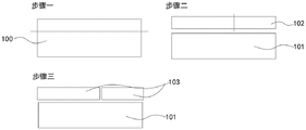
At present, the stamping forming of the side coaming is generally completed through two stamping operations, as shown in fig. 6, firstly, one stamping cutter completes the first stamping of the material plate along the dotted line in the step one, and then, the other stamping cutter completes the second stamping of the material plate along the dotted line in the step two, so that the formed side coaming and two waste plates in the step three are obtained.
However, this kind of stamping forming process has a serious problem, namely two stamping cutters that accomplish twice punching press are mutual butt in fact, so can have a very little clearance between the butt position of two cutters, this just causes the side bounding wall to accomplish twice punching press back and forth by two cutters respectively, the edge of side bounding wall can have a convex sharp burr in the position of the connection position of twice stamping forming, and this burr can cause very serious harmful effects to the required precision of side bounding wall, consequently must pass through subsequent handling, polish the edge of side bounding wall, thereby eliminate the burr. This causes the complexity of the side wall plate forming process and greatly reduces the working efficiency.
Disclosure of Invention
In view of the above, the invention provides a stamping die and a stamping method for a side coaming for a vehicle, which can avoid burrs from being generated on the edge of the side coaming.
The technical scheme of the invention is realized as follows: the invention provides a stamping die for a side wall plate for a vehicle, which comprises a cutter and a die holder, wherein the cutter and the die holder are matched and used for stamping a material plate into the side wall plate, the cutter comprises a first cutter body and a second cutter body, the first cutter body and the second cutter body are sequentially matched with the die holder in sequence, the first cutter body is matched with the die holder and used for stamping the material plate to produce a formed side wall plate and waste materials, the second cutter body is abutted against the side surface of the first cutter body and is positioned at one side of the waste materials produced by stamping of the first cutter body, and the second cutter body is matched with the die holder and used for stamping the waste materials to produce two waste plates.
On the basis of the above technical scheme, preferably, the die holder includes a first seat body, a second seat body and a third seat body, the first seat body, the second seat body and the third seat body are sequentially tightly attached to the edge of the side enclosing plate and are sequentially abutted, the first seat body has a first matching portion, the second seat body has a second matching portion and a third matching portion, the third seat body has a fourth matching portion, two ends of the first matching portion, the second matching portion and the fourth matching portion respectively extend along the edge of the side enclosing plate and are simultaneously matched with the first cutter body, the third matching portion is arranged in a cross manner with the extending direction of the second matching portion, and the third matching portion is matched with the second cutter body.
Further preferably, the die holder further includes a fourth die base, the second die base and the third die base are arranged at an interval, the fourth die base is arranged between the second die base and the third die base and is abutted against the second die base and the third die base, the fourth die base can move relative to the second die base along a direction parallel to the stamping direction of the cutter, the fourth die base has a first position and a second position, the fourth die base can be matched with the first cutter and move to the first position, or the fourth die base is abutted against the second cutter and is switched to the second position.
Further preferably, the end of the third matching part intersected with the second matching part extends into the space between the second seat body and the third seat body; the fourth seat body is provided with a fifth matching part, two ends of the fifth matching part respectively extend along the edge of the side wall plate and are matched with the first blade, and two ends of the fifth matching part respectively abut against the end part of the third matching part crossed with the second matching part and the end part of the fourth matching part facing the second matching part; the second cutter body is provided with a protruding part which moves synchronously with the second cutter body, the protruding part is matched with the third matching part and inserted into the interval between the second seat body and the third seat body, and the protruding part can selectively abut against the fifth matching part and push the fourth seat body to be switched to the second position.
Preferably, the first matching part, the second matching part, the fourth matching part and the fifth matching part are all flush with the side surfaces matched with the first cutter body; when the fourth seat is located at the first position, the end faces of the first matching portion, the second matching portion, the third matching portion, the fourth matching portion and the fifth matching portion towards the punching direction of the cutter are flush with each other.
Still further preferably, the width of the protruding portion along the extending direction of the fifth matching portion is not greater than the spacing width between the second seat body and the third seat body.
Further preferably, the cutting tool further comprises a linear output mechanism, the linear output mechanism comprises a fixed end and a movable end, the fixed end is arranged on a stable horizontal plane, the movable end is connected to the end face, away from the cutting tool, of the fourth seat body, and the linear output mechanism drives the fourth seat body to move along the direction parallel to the punching direction of the cutting tool.
Still further preferably, the linear output mechanism is a nitrogen spring or a nitrogen cylinder.
On the other hand, the invention also provides a stamping method of the side enclosing plate for the vehicle, which uses the stamping die to complete the stamping forming of the side enclosing plate for the vehicle and comprises the following steps,
placing a material plate between a cutter and a die holder, wherein a first cutter body is simultaneously matched with a first matching part of a first base body, a second matching part of a second base body and a fourth matching part of a third base body, and the first cutter body punches the material plate and produces a formed side enclosing plate and waste materials;
the second cutter body is matched with a third matching part of the second seat body, and the second cutter body punches the waste materials and produces two waste plates;
and step three, the cutter is far away from the die holder to complete stamping.
On the basis of the above technical solution, preferably, in the first step, the fourth seat body is initially located at the first position, and the first blade body is also matched with the fifth matching part of the fourth seat body at the same time;
in the second step, the protruding part moves synchronously with the second cutter body and is inserted into the space between the second seat body and the third seat body, and the protruding part abuts against the fifth matching part and pushes the fourth seat body to be switched to the second position;
in the third step, the second cutter body is far away from the fourth seat body, and meanwhile, the linear output mechanism drives the fourth seat body to reset to the first position.
Compared with the prior art, the stamping die and the stamping method for the side coaming for the vehicle have the following beneficial effects that:
(1) the invention adopts twice stamping, firstly uses the first cutter body to cut the whole waste material from the material plate, and then uses the second cutter body to cut the waste material into two waste plates, thereby avoiding generating burrs on the stamping forming surface of the edge of the side wall plate, greatly improving the forming effect, saving the subsequent step of grinding the burrs, and improving the working efficiency.
(2) The fourth base body capable of moving is adopted, other base bodies can be matched with the first cutter body to complete primary stamping, and meanwhile, the fourth base body can be selectively abutted against the second cutter body, so that sufficient stroke space can be provided for the second cutter body when the second cutter body performs stamping.
Drawings
In order to more clearly illustrate the embodiments of the present invention or the technical solutions in the prior art, the drawings used in the description of the embodiments or the prior art will be briefly described below, it is obvious that the drawings in the following description are only some embodiments of the present invention, and for those skilled in the art, other drawings can be obtained according to the drawings without creative efforts.
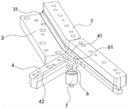
FIG. 1 is a partial perspective view of a stamping die of the present invention;
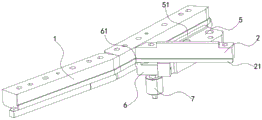
FIG. 2 is a partial perspective view of another perspective of the stamping die of the present invention;
FIG. 3 is a partial perspective view of another perspective of the stamping die of the present invention;
FIG. 4 is a partial perspective view of another perspective of the stamping die of the present invention;
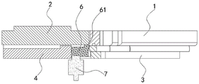
FIG. 5 is a side cross-sectional view of a fourth seat according to the present invention;
FIG. 6 is a schematic diagram of steps of a conventional side panel punch forming method;
FIG. 7 is a schematic diagram of the steps of the side wall plate stamping forming method using the stamping die of the present invention.
In the figure: 100. a material plate; 101. side coaming plates; 102. waste materials; 103. waste boards; 1. a first cutter body; 2. a second blade body; 21. a protrusion; 3. a first seat body; 31. a first mating portion; 4. a second seat body; 41. a second mating portion; 42. a third mating portion; 5. a third seat body; 51. a fourth mating portion; 6. a fourth seat body; 61. a fifth mating portion; 7. and a linear output mechanism.
Detailed Description
The technical solutions in the embodiments of the present invention will be clearly and completely described below with reference to the embodiments of the present invention, and it is obvious that the described embodiments are only a part of the embodiments of the present invention, and not all of the embodiments. All other embodiments, which can be obtained by a person skilled in the art without any inventive step based on the embodiments of the present invention, are within the scope of the present invention.
As shown in fig. 1 and fig. 2, the stamping die for a side panel for a vehicle of the present invention includes a cutter and a die holder, which are matched to stamp a material plate 100 into a side panel 101.
Specifically, the cutter includes a first cutter body 1 and a second cutter body 2, and the mold base includes a first base body 3, a second base body 4 and a third base body 5.
The first cutter body 1 and the second cutter body 2 are sequentially matched with the die holder, the position of the first cutter body 1 is kept unchanged after punching is completed, and the second cutter body 2 punches at the moment so as to punch twice.
The first cutter body 1 is matched with the die holder and used for punching a material plate 100 to produce a formed side wall plate 101 and waste materials 102. The formed side gusset 101 can be obtained by the first punching and the first cutter body 1 cuts the edge of the side gusset 101 entirely, so that no burr is generated on the edge of the side gusset 101.
The second cutter body 2 is abutted against the side surface of the first cutter body 1 and is positioned on one side of the first cutter body 1 where the waste material 102 is produced by stamping, and the second cutter body 2 is matched with the die holder and is used for producing two waste plates 103 by stamping the waste material 102. The purpose of this is that the scrap 102 is large in area and thus the scrap 102 is difficult to pass through the recovery opening provided therebelow, and therefore the scrap 102 is cut into two small-area waste plates 103 by the second punching, and can be dropped into the recovery opening and recovered.
The first seat body 3, the second seat body 4 and the third seat body 5 are sequentially arranged close to the edge of the side enclosing plate 101 and are sequentially abutted, so that the shape matched with the edge of the side enclosing plate 101 is enclosed, and the first cutter body 1 is conveniently formed by punching.
Specifically, the first seat body 3 has a first matching portion 31, the second seat body 4 has a second matching portion 41 and a third matching portion 42, the third seat body 5 has a fourth matching portion 51, and two ends of the first matching portion 31, the second matching portion 41 and the fourth matching portion 51 respectively extend along the edge of the side wall plate 101 and are simultaneously matched with the first knife body 1; the third engaging portion 42 is provided to intersect with the extending direction of the second engaging portion 41, and the third engaging portion 42 engages with the second blade 2, so that the second press can be performed to cut the scrap 102 by the second blade 2.
By adopting the technical scheme, compared with the existing stamping method, the burrs at the edge of the side coaming 101 can be effectively eliminated; however, in fact, in the prior art, there is a punching apparatus and a punching process for punching out the entire side panel 101 by the first punching, but none of these apparatuses and techniques has solved the problem. Because the first cutter body 1 is immobile after the punching is finished, the positions of the side coaming 101 and the waste 102 produced by the punching are also kept unchanged, and the second cutter body 2 falls down for punching; however, even if the second cutter body 2 is pressed against the side surface of the first cutter body 1, it is difficult to ensure that the portion of the second cutter body 2 abutting against the first cutter body 1 can accurately and reliably cut off the waste 102, and at the same time, the die holder also abuts against the second cutter body 2, so that the second cutter body 2 is prevented from being pressed downwards, and thus burrs are still formed between the waste 102 and the side wall plate 101; in order to solve the problem in the prior art, the waste 102 is manually taken out of the die after the first stamping is completed, which causes the problems of complex process and low efficiency.
The present invention, however, is designed to solve this problem in a second embodiment.
As shown in fig. 1, in conjunction with fig. 3, the die holder further includes a fourth die holder 6.
The second seat 4 and the third seat 5 are spaced apart from each other, so as to provide a stroke space for pressing down and cutting off the waste 102 for stamping the second cutter body 2.
The fourth seat body 6 is arranged between the second seat body 4 and the third seat body 5 and is abutted against the second seat body and the third seat body, the fourth seat body 6 can move relative to the second seat body 4 along the direction parallel to the stamping direction of the cutter, the movable fourth seat body 6 is arranged to move in an interval, and different positions are switched according to different requirements of two stamping steps.
Specifically, the fourth seat 6 has a first position and a second position; when the first stamping is carried out, the fourth seat body 6 is positioned at the first position of the initial state, and the fourth seat body 6 can be matched with the first cutter body 1 so as to fill the gap; when the second punching is performed, the fourth seat 6 abuts against the second cutter body 2, and the second cutter body 2 presses the fourth seat 6 to move down and switch to the second position, so that the gap is kept, and a stroke space is provided for the second cutter body 2.
In addition, the present invention is designed in a third embodiment in order to improve the punching effect of the second cutter body 2.
As shown in fig. 1, with reference to fig. 4, the end of the third engaging portion 42 intersecting the second engaging portion 41 extends into the space between the second seat 4 and the third seat 5.
The fourth seat 6 has a fifth matching portion 61, two ends of the fifth matching portion 61 respectively extend along the edge of the side gusset 101 and match with the first knife body 1, two ends of the fifth matching portion 61 respectively abut against the end of the third matching portion 42 intersected with the second matching portion 41 and the end of the fourth matching portion 51 facing the second matching portion 41.
The second blade body 2 has a protrusion 21, the protrusion 21 moves synchronously with the second blade body 2, the protrusion 21 is engaged with the third engaging portion 42 and inserted into the gap between the second seat 4 and the third seat 5, and the protrusion 21 selectively abuts against the fifth engaging portion 61 and pushes the fourth seat 6 to switch to the second position. The protrusion 21 increases the punching stroke of the second cutter body 2, thereby enabling effective cutting of the scrap 102.
Specifically, the first mating portion 31, the second mating portion 41, the fourth mating portion 51, and the fifth mating portion 61 are all flush with the side surface of the first tool body 1, and when the fourth seat 6 is located at the first position, the end surfaces of the first mating portion 31, the second mating portion 41, the third mating portion 42, the fourth mating portion 51, and the fifth mating portion 61 facing the punching direction of the cutter are all flush with each other, so as to be precisely matched with the punching surface of the first tool body 1.
Meanwhile, in order to make the surface protrusion 21 wider, it may abut against the fourth matching portion 51, and the width of the protrusion 21 along the extending direction of the fifth matching portion 61 is not greater than the width of the space between the second seat 4 and the third seat 5.
As a fourth embodiment, the present invention needs to realize the moving performance of the fourth seat 6, and also needs to ensure that the mechanism for driving the fourth seat 6 to move does not interfere with the normal operation of the press die.
As shown in fig. 1, with reference to fig. 5, the device further includes a linear output mechanism 7, the linear output mechanism 7 includes a fixed end and the fixed end is disposed on a stable horizontal plane, the linear output mechanism 7 further includes a movable end and the movable end is connected to an end surface of the fourth seat 6 away from the cutter, and the linear output mechanism 7 drives the fourth seat 6 to move along a direction parallel to the punching direction of the cutter. Preferably, the linear output mechanism 7 is a nitrogen spring or a nitrogen cylinder, and has the advantages of small equipment volume, large elasticity, long stroke, stable work and the like.
Example five:
as shown in fig. 1 and in combination with fig. 7, the invention provides a method for stamping a side panel for a vehicle, which uses the stamping die to complete stamping forming of the side panel 101 for the vehicle, and comprises the following steps,
step one, a material plate 100 is placed between a cutter and a die holder, a first cutter body 1 is simultaneously matched with a first matching part 31 of a first base body 3, a second matching part 41 of a second base body 4 and a fourth matching part 51 of a third base body 5, and the first cutter body 1 punches the material plate 100 and produces a formed side wall plate 101 and a waste material 102;
step two, the second cutter body 2 is matched with the third matching part 42 of the second seat body 4, and the second cutter body 2 punches the waste material 102 and produces two waste plates 103;
and step three, the cutter is far away from the die holder to complete stamping.
Example six:
the invention also provides a stamping method of the side enclosing plate for the vehicle, which uses the stamping die to complete the stamping forming of the side enclosing plate 101 for the vehicle and comprises the following steps,
step one, in an initial state, the fourth seat body 6 is located at a first position; a material plate 100 is placed between the cutter and the die holder, and the first cutter body 1 is simultaneously matched with the first matching part 31 of the first seat body 3, the second matching part 41 of the second seat body 4, the fourth matching part 51 of the third seat body 5 and the fifth matching part 61 of the fourth seat body 6; the first cutter body 1 punches the material plate 100 and produces a formed side wall plate 101 and waste materials 102;
step two, the second knife body 2 is matched with the third matching part 42 of the second seat body 4, the protruding part 21 moves synchronously with the second knife body 2 and is inserted into the interval between the second seat body 4 and the third seat body 5, and the protruding part 21 abuts against the fifth matching part 61 and pushes the fourth seat body 6 to be switched to the second position; the second cutter body 2 punches the waste material 102 and produces two waste plates 103;
thirdly, the cutter is far away from the die holder to complete stamping; at this time, the second cutter body 2 is far away from the fourth seat body 6, and simultaneously the linear output mechanism 7 drives the fourth seat body 6 to reset to the first position.
The above description is only for the purpose of illustrating the preferred embodiments of the present invention and is not to be construed as limiting the invention, and any modifications, equivalents, improvements and the like that fall within the spirit and principle of the present invention are intended to be included therein.
Claims (10)
1. The utility model provides a stamping die of automobile-used side bounding wall, includes cutter and die holder, cutter and die holder match and become side bounding wall (101) with flitch (100) punching press, its characterized in that: the cutter comprises a first cutter body (1) and a second cutter body (2), wherein the first cutter body (1) and the second cutter body (2) are sequentially matched with a die holder, the first cutter body (1) is matched with the die holder and is used for punching a side enclosing plate (101) and waste materials (102) which are formed by the material plates (100), the second cutter body (2) is abutted against the side surface of the first cutter body (1) and is positioned on one side of the first cutter body (1) for punching the waste materials (102), and the second cutter body (2) is matched with the die holder and is used for punching the waste materials (102) to produce two waste plates (103).
2. The stamping die for a side panel for a vehicle as claimed in claim 1, wherein: the die holder comprises a first seat body (3), a second seat body (4) and a third seat body (5), the first seat body (3), the second seat body (4) and the third seat body (5) are sequentially arranged close to the edge of the side coaming plate (101) and are sequentially abutted, the first seat body (3) is provided with a first matching part (31), the second seat body (4) is provided with a second matching part (41) and a third matching part (42), the third seat body (5) is provided with a fourth matching part (51), two ends of the first matching part (31), the second matching part (41) and the fourth matching part (51) respectively extend along the edge of the side enclosing plate (101) and are simultaneously matched with the first cutter body (1), the third matching part (42) and the second matching part (41) are arranged in a crossed mode in the extending direction, and the third matching part (42) is matched with the second cutter body (2).
3. The stamping die for a side panel for a vehicle as claimed in claim 2, wherein: the die holder further comprises a fourth base body (6), the second base body (4) and the third base body (5) are arranged at intervals, the fourth base body (6) is arranged between the second base body (4) and the third base body (5) and is abutted against the second base body and the third base body, the fourth base body (6) can move relative to the second base body (4) along the direction parallel to the stamping direction of the cutter, the fourth base body (6) is provided with a first position and a second position, the fourth base body (6) can be matched with the first cutter body (1) and can move to the first position, or the fourth base body (6) is abutted against the second cutter body (2) and can be switched to the second position.
4. The stamping die for a side panel for a vehicle as claimed in claim 3, wherein: the end part of the third matching part (42) which is crossed with the second matching part (41) extends into the interval between the second seat body (4) and the third seat body (5);
the fourth base body (6) is provided with a fifth matching part (61), two ends of the fifth matching part (61) respectively extend along the edge of the side enclosing plate (101) and are matched with the first cutter body (1), two ends of the fifth matching part (61) respectively abut against the end part of the third matching part (42) crossed with the second matching part (41) and the end part of the fourth matching part (51) facing the second matching part (41);
the second cutter body (2) is provided with a protruding portion (21), the protruding portion (21) moves synchronously with the second cutter body (2), the protruding portion (21) is matched with the third matching portion (42) and is inserted into an interval between the second seat body (4) and the third seat body (5), and the protruding portion (21) can selectively abut against the fifth matching portion (61) and push the fourth seat body (6) to be switched to the second position.
5. The stamping die for a side panel for a vehicle as claimed in claim 4, wherein: the first matching part (31), the second matching part (41), the fourth matching part (51) and the fifth matching part (61) are flush with the matched side surfaces of the first cutter body (1) at the same time;
when the fourth seat body (6) is located at the first position, the end faces of the first matching portion (31), the second matching portion (41), the third matching portion (42), the fourth matching portion (51) and the fifth matching portion (61) towards the punching direction of the cutter are flush with each other.
6. The stamping die for a side panel for a vehicle as claimed in claim 4, wherein: the width of the protruding part (21) along the extending direction of the fifth matching part (61) is not more than the spacing width between the second seat body (4) and the third seat body (5).
7. The stamping die for a side panel for a vehicle as claimed in claim 3, wherein: still include sharp output mechanism (7), sharp output mechanism (7) include a stiff end and stiff end setting on firm horizontal plane, sharp output mechanism (7) still include a expansion end and connect on fourth pedestal (6) keep away from the terminal surface of cutter, sharp output mechanism (7) drive fourth pedestal (6) are along the direction removal that is on a parallel with cutter punching press direction.
8. The stamping die for a side panel for a vehicle as claimed in claim 7, wherein: the linear output mechanism (7) is a nitrogen spring or a nitrogen cylinder.
9. A stamping method for a side coaming for a vehicle is characterized in that: the press forming of the side panel (101) for a vehicle is completed by using the press die according to any one of claims 1 to 8, including the steps of,
placing a material plate (100) between a cutter and a die holder, wherein a first cutter body (1) is matched with a first matching part (31) of a first base body (3), a second matching part (41) of a second base body (4) and a fourth matching part (51) of a third base body (5) at the same time, and the first cutter body (1) punches the material plate (100) and produces a formed side enclosing plate (101) and waste materials (102);
secondly, the second cutter body (2) is matched with a third matching part (42) of the second seat body (4), and the second cutter body (2) punches the waste material (102) and produces two waste plates (103);
and step three, the cutter is far away from the die holder to complete stamping.
10. The method for punching a side panel for a vehicle according to claim 9, wherein: in the first step, the fourth seat (6) is initially located at the first position, and the first cutter body (1) is simultaneously matched with a fifth matching part (61) of the fourth seat (6);
in the second step, the protruding part (21) moves synchronously with the second cutter body (2) and is inserted into the gap between the second seat body (4) and the third seat body (5), and the protruding part (21) abuts against the fifth matching part (61) and pushes the fourth seat body (6) to switch to the second position;
in the third step, the second cutter body (2) is far away from the fourth seat body (6), and meanwhile, the linear output mechanism (7) drives the fourth seat body (6) to reset to the first position.
Priority Applications (1)
| Application Number | Priority Date | Filing Date | Title |
|---|---|---|---|
| CN202111391635.5A CN114226543A (en) | 2021-11-23 | 2021-11-23 | Stamping die and stamping method for side coaming for vehicle |
Applications Claiming Priority (1)
| Application Number | Priority Date | Filing Date | Title |
|---|---|---|---|
| CN202111391635.5A CN114226543A (en) | 2021-11-23 | 2021-11-23 | Stamping die and stamping method for side coaming for vehicle |
Publications (1)
| Publication Number | Publication Date |
|---|---|
| CN114226543A true CN114226543A (en) | 2022-03-25 |
Family
ID=80750510
Family Applications (1)
| Application Number | Title | Priority Date | Filing Date |
|---|---|---|---|
| CN202111391635.5A Pending CN114226543A (en) | 2021-11-23 | 2021-11-23 | Stamping die and stamping method for side coaming for vehicle |
Country Status (1)
| Country | Link |
|---|---|
| CN (1) | CN114226543A (en) |
Citations (7)
| Publication number | Priority date | Publication date | Assignee | Title |
|---|---|---|---|---|
| CN202427794U (en) * | 2011-11-30 | 2012-09-12 | 长城汽车股份有限公司 | Simultaneous trimming mechanism of scrap cutter on mould |
| CN202570945U (en) * | 2012-05-25 | 2012-12-05 | 烟台泰利汽车模具制造有限公司 | Floating-type waste cutter device for blanking die |
| CN203292310U (en) * | 2013-05-18 | 2013-11-20 | 奇瑞汽车股份有限公司 | Trimming mold movable waste cutter of automobile covering part |
| CN203470611U (en) * | 2013-09-23 | 2014-03-12 | 上海赛科利汽车模具技术应用有限公司 | Floating waste knife mechanism |
| CN204074879U (en) * | 2013-12-09 | 2015-01-07 | 四川成飞集成科技股份有限公司 | A kind of deburring scrap cutter |
| CN209077537U (en) * | 2018-09-29 | 2019-07-09 | 北京汽车股份有限公司 | Floating waste material cutter mechanism |
| CN110193547A (en) * | 2019-05-28 | 2019-09-03 | 瑞鹄汽车模具股份有限公司 | A kind of trimming method of floating waste material cutter mechanism and the Trimming Die equipped with the mechanism |
-
2021
- 2021-11-23 CN CN202111391635.5A patent/CN114226543A/en active Pending
Patent Citations (7)
| Publication number | Priority date | Publication date | Assignee | Title |
|---|---|---|---|---|
| CN202427794U (en) * | 2011-11-30 | 2012-09-12 | 长城汽车股份有限公司 | Simultaneous trimming mechanism of scrap cutter on mould |
| CN202570945U (en) * | 2012-05-25 | 2012-12-05 | 烟台泰利汽车模具制造有限公司 | Floating-type waste cutter device for blanking die |
| CN203292310U (en) * | 2013-05-18 | 2013-11-20 | 奇瑞汽车股份有限公司 | Trimming mold movable waste cutter of automobile covering part |
| CN203470611U (en) * | 2013-09-23 | 2014-03-12 | 上海赛科利汽车模具技术应用有限公司 | Floating waste knife mechanism |
| CN204074879U (en) * | 2013-12-09 | 2015-01-07 | 四川成飞集成科技股份有限公司 | A kind of deburring scrap cutter |
| CN209077537U (en) * | 2018-09-29 | 2019-07-09 | 北京汽车股份有限公司 | Floating waste material cutter mechanism |
| CN110193547A (en) * | 2019-05-28 | 2019-09-03 | 瑞鹄汽车模具股份有限公司 | A kind of trimming method of floating waste material cutter mechanism and the Trimming Die equipped with the mechanism |
Similar Documents
| Publication | Publication Date | Title |
|---|---|---|
| CN210023450U (en) | Bending and stamping integrated die | |
| JP2611128B2 (en) | Cutting die for follow-up cutting | |
| CN111906192A (en) | High-precision stamping mechanism for high-density small-space multi-PIN fisheye terminal | |
| CN109318288B (en) | Integrated device suitable for punching automobile sealing strips | |
| CN211191593U (en) | Compound burring device of aluminium die casting | |
| CN109909372A (en) | A kind of automotive high-performance micromotor shell no waste mine side die cutting die | |
| CN114226543A (en) | Stamping die and stamping method for side coaming for vehicle | |
| CN217021311U (en) | Cutting jig | |
| CN216540387U (en) | Metal photo frame punching machine | |
| CN217393464U (en) | Double-sided punching machine | |
| CN210358839U (en) | Punch forming die for unlocking handle of automobile seat | |
| CN211588182U (en) | Cutting device | |
| JPH06269869A (en) | Press device for work | |
| CN209849651U (en) | Side cutting die based on same datum plane | |
| CN213257358U (en) | Processing device | |
| CN210676605U (en) | Composite die for blanking high-precision thick plate | |
| CN2130616Y (en) | Cutting-off male die | |
| CN217070424U (en) | Two-side flanging and punching compound die | |
| CN217667119U (en) | General stub bar material tail welding set | |
| CN221184381U (en) | Prevent punching device of deformation | |
| CN109692909A (en) | A kind of preparation process of connector fish forked terminal | |
| CN216989501U (en) | Punching tool for continuous die | |
| CN218340802U (en) | Corner bending and blanking die machining structure | |
| CN220574470U (en) | Punching die for material belt | |
| CN212703899U (en) | Shearing tool of double-punch combined punching and shearing machine |
Legal Events
| Date | Code | Title | Description |
|---|---|---|---|
| PB01 | Publication | ||
| PB01 | Publication | ||
| SE01 | Entry into force of request for substantive examination | ||
| SE01 | Entry into force of request for substantive examination | ||
| RJ01 | Rejection of invention patent application after publication |
Application publication date: 20220325 |
|
| RJ01 | Rejection of invention patent application after publication |