Disclosure of Invention
Technical problem to be solved
Aiming at the defects of the prior art, the invention provides a method for self-adjusting a weighing sensor, which solves the problem that in practical application, even professional technicians cannot find the optimal numerical values, namely, the equipment can be ensured to reach the parameter values with highest precision and highest speed, the parameter values are influenced by material characteristics, and the parameters which are set before can be used only by changing and debugging the parameters again because of the change of the site, so that the uncertainty of the normal operation of the site is increased.
(II) technical scheme
In order to achieve the purpose, the invention is realized by the following technical scheme: a method of self-adjusting a load cell, comprising the steps of:
the method comprises the following steps that firstly, a first scale is started, and an instrument searches rough fast adding lead, medium adding lead and slow adding lead of the first scale in a self-adaptive manner;
step two, starting a second scale, enabling the instrument to enter a fast-adding state, setting fast-adding forbidden judgment time, closing a large-throw output signal when the weight of the material is larger than or equal to a target value, namely the fast-adding advance, and recording the fast-adding charging time;
step three, the instrument enters a charging state, the most appropriate charging forbidden judgment time is found by judging the linear fitting K value, when the material weight is larger than or equal to the target value-the charging advance, the charging output signal is closed, and the charging time is recorded;
the meter enters a slow charging state, the most appropriate slow charging forbidden judgment time is found by judging the linear fitting K value, when the weight of the material is larger than or equal to the target value-the slow charging advance, the small-throw output signal is closed, and the slow charging time is recorded and used for correcting the medium charging advance;
step five, the instrument enters a constant value state, the weight of the material of the current scale is recorded and is used for correcting the slow advance amount, if the number of times is less than 5, the slow advance amount only needs to be corrected by 50% according to the deviation value of the previous scale, and after the number of times exceeds 5 scales, correction is carried out according to a normal algorithm;
and step six, summarizing the charging information of the scale, and correcting the lead parameter of the scale for the next scale for discharging.
Preferably, in the first step, after the first scale is started, the quick-adding door is opened, after the meter detects that the weight of the weighing hopper is increased by 100 divisions, the meter closes the adding door, waits for the stability of the scale body, records the current weight as SP1_ W, and the current weight is the drop value when the quick-adding door is opened, that is, the weight of the material in the quick-adding air, then the input signal in the output of the meter enters the medium-adding state, the medium-adding state lasts for 2 seconds, then the meter closes the medium-adding, the equipment enters the small-adding state, after waiting for 1 second, records the current SP2_ W, then closes the small-adding, waits for the stability of the weight, and records the current weight as SP3_ W.
Preferably, the slow advance = SP3_ W-SP 2_ W, the medium advance = SP3_ W-SP 1_ W, and the fast advance = SP3_ W are calculated.
Preferably, in the third step, when the feeding is carried out quickly, since the weight is always fed, the K value linearly calculated by the weight is always larger than 0.
Preferably, when the large throw output signal is turned off, the determination prohibition time in the timing is started, when the K value is less than or equal to 0 for the first time, it is indicated that the rapid addition fall weight has completely entered the metering hopper, when the K value is greater than or equal to 0 again, it is indicated that the whole impact force of the rapid addition material has completely ended, and then the determination of the determination prohibition time in the timing is ended.
Preferably, after the medium input prohibiting time is over, when the medium input output signal is turned off (the weight of the material is more than or equal to the target value-the medium input advance), the small input prohibiting time can be found in the same way.
Preferably, in the step five, the slow advance correction mode is that 5 times of feeding result deviation values are continuously taken, the maximum value and the minimum value are removed, then the rest 3 scale result values are averaged, and then half of the average value is taken for slow advance correction.
Preferably, the medium feeding lead is the weight of the material in the air and the weight value of all the small feeds added later after the medium feeding is closed, before the medium feeding lead is adjusted, the feeding time of the small feeds needs to be limited in advance, that is, the small feeding time is within an interval range, if the small feeding time is longer than the time, the whole feeding time is longer, and if the small feeding time is shorter than the time, the feeding is unstable, so that after the medium feeding is closed, after the slow feeding inhibition judgment time, before the small feeds are closed, the small feeding flow is basically stable, the small feeding flow can be calculated, and then the weight of the material of the small feeds exceeding the feeding time range is calculated according to the small feeding flow meter for correcting the medium feeding lead.
Preferably, the large feeding lead correction principle and the medium feeding lead are used for correcting the large feeding lead by limiting the medium feeding time range and the medium feeding numerical value.
Preferably, in the fourth step, the meter continuously reads 6, 12, 24 and 48 weight data under different analog-to-digital conversions, linear fitting is performed on the sampled weight data, and then after the weight data is subjected to the next AD conversion, the predicted weight value is obtained by linear fitting, which participates in the weight judgment of the meter, so that the inaccurate judgment weight caused by mechanical vibration in the working process of the equipment can be maximally processed.
(III) advantageous effects
The invention provides a method for self-adjusting a weighing sensor. The method has the following beneficial effects:
(1) the self-adaptive method for the weighing sensor has the self-adaptive essence that the fast, medium and slow adding lead is manually set without manually debugging equipment, and the instrument automatically searches for other parameters such as the fast, medium and slow adding lead according to the characteristics of the current equipment and the current material and can reach the optimal state.
(2) According to the method for self-adjusting the weighing sensor, after the self-adaptive scheme is used, if the meter is replaced by materials or other equipment on site, parameters do not need to be adjusted manually, the meter can automatically find appropriate quantitative parameters only by restarting the meter, and the use requirements of end users are greatly facilitated.
Detailed Description
The technical solutions in the embodiments of the present invention will be clearly and completely described below with reference to the drawings in the embodiments of the present invention, and it is obvious that the described embodiments are only a part of the embodiments of the present invention, and not all of the embodiments. All other embodiments, which can be derived by a person skilled in the art from the embodiments given herein without making any creative effort, shall fall within the protection scope of the present invention.
A method of self-adjusting a load cell, comprising the steps of:
the method comprises the following steps that firstly, a first scale is started, and an instrument searches rough fast adding lead, medium adding lead and slow adding lead of the first scale in a self-adaptive manner;
step two, starting a second scale, enabling the instrument to enter a fast-adding state, setting fast-adding forbidden judgment time, closing a large-throw output signal when the weight of the material is larger than or equal to a target value, namely the fast-adding advance, and recording the fast-adding charging time;
step three, the instrument enters a charging state, the most appropriate charging forbidden judgment time is found by judging the linear fitting K value, when the material weight is larger than or equal to the target value-the charging advance, the charging output signal is closed, and the charging time is recorded;
the meter enters a slow charging state, the most appropriate slow charging forbidden judgment time is found by judging the linear fitting K value, when the weight of the material is larger than or equal to the target value-the slow charging advance, the small-throw output signal is closed, and the slow charging time is recorded and used for correcting the medium charging advance;
step five, the instrument enters a constant value state, the weight of the material of the current scale is recorded and is used for correcting the slow advance amount, if the number of times is less than 5, the slow advance amount only needs to be corrected by 50% according to the deviation value of the previous scale, and after the number of times exceeds 5 scales, correction is carried out according to a normal algorithm;
and step six, summarizing the charging information of the scale, and correcting the lead parameter of the scale for the next scale for discharging.
The first step is as follows: accurate weight values were collected (Linear fitting algorithm)
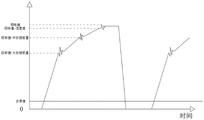
In an embodiment of the invention: for the controller, the instrument determines when to output the control signal according to the weight value, such as when the material weight is larger than or equal to the target value and the advance is increased, the instrument turns off the large throw signal, so the accuracy of the weight value is important for the instrument. However, in an industrial field environment, the vibration of the equipment can cause the weight value to bounce all the time, so that the weight value collected by the instrument is not very accurate, as shown in fig. 3: and (3) forbidding judging the time weight point diagram 3, wherein the weight value is deviated from the actual value due to vibration. Therefore, stable weight data needs to be acquired before the scheme is implemented.
The meter can perform 120/s, 240/s, 480/s, 960/s AD conversion per second (i.e., the meter can convert as much weight data per second). In a software program, 6, 12, 24 and 48 weight data are continuously read under different analog-to-digital conversions respectively, linear fitting is carried out on the sampled weight data (note 2), and then after the weight data are subjected to the next AD conversion, the weight values predicted by the linear fitting are used for participating in the weight judgment of the instrument, so that the inaccurate judgment weight caused by mechanical vibration in the working process of equipment can be treated to the greatest extent.
Examples of linear fitting schemes are: the meter collected 7 sets of weight data 10, 13, 18, 19, 23, 25, 35, then to use the linear fit, each collected data was added a number, respectively, as follows: (1, 10), (2, 13), (3, 18), (4, 19), (5, 23), (6, 25) and (7, 35) wherein the first number in brackets is mainly used for identifying and predicting the weight data of the second weight. Since the number of participating linear fits is 7, the data will automatically fill in when there is a new weight data transition. Then after the 7 th data is filled, a linear fit is needed to the 7 data, and the calculated data is 32, and when the weight data of the meter is judged, 32 is used instead of 35.
The second step is that: finding suitable time for forbidding judgment
The equipment adds the state of opening the door soon, when equipment carries out the material loading, the weight that shows on the instrument is (shows weight = actual weight + impact force), and the impact force is big more when the quick door is opened. As shown in fig. 3: the judgment forbidding time weight point diagram 3 shows that due to the influence of impact force, the instrument has no way of obtaining an actual weight real-time control output signal, so that the feeding of the equipment is inaccurate. If the fast adding and forbidding time, the medium adding and forbidding time and the slow adding and forbidding time are too large, the charging time of the equipment is too long, and if the fast adding and forbidding time, the medium adding and forbidding time and the slow adding and forbidding time are too small, the charging of the equipment is overshot and the charging is inaccurate. Then the best time to deny the decision needs to be collected.
In the actual weight charging process, the weight change of the meter in the forbidden judgment time is as shown in fig. 3: decision-forbidden time weight point diagram 3 is shown. And in the fast-adding state, the large-throw output signal is closed when the weight of the material is more than or equal to the target value and the fast-adding advance is carried out. When the rapid drop falls completely into the hopper, then the impact force of the meter will begin to decrease, i.e. as shown in fig. 3: and (3) reaching the highest point of forbidden judgment as shown in the weight point diagram 3, and reaching the lowest point of forbidden judgment after the quick impact force disappears gradually. Therefore, in the implementation of the scheme, the judgment prohibiting time closest to the actual judgment prohibiting time needs to be found.
As shown in fig. 3: the forbidden time gravimetric point diagram shows that when the material is added quickly, the K value which is linearly fit for the weight is always greater than 0 because the weight is always added. When the large throw output signal is closed, the forbidden judgment time in timing is started, when the K value is less than or equal to 0 for the first time, the fast adding fall weight completely enters the measuring hopper, when the K value is more than or equal to 0 again, the whole fast adding material impact force is completely finished, and then the forbidden judgment time in the timing is finished. And after the medium adding forbidding time is over, closing the medium adding output signal when the weight of the material is more than or equal to the target value and the medium adding lead. In the same way, a small tie-in time can be found.
The third step: correcting fast plus lead amount/medium plus lead amount/slow plus lead amount
The slow advance is the weight of the material in the air when the small throw is closed, the weight of the material falls into the weighing hopper, and the weight of the material just reaches the set target value, so the slow advance is the most suitable slow advance. The reason that the slow advance is required to be adjusted and corrected in real time in practical application is that on many sites, there is no way to ensure that the material in the feeding hopper is always kept unchanged, and after the height of the material in the feeding hopper is changed, the discharging speed of the feeding opening is changed (the bin pressure caused by the height of the material is changed), so that the error of the feeding result is increased.
The slow advance correction mode is that the deviation value of the charging result is continuously obtained for 5 times, the maximum value and the minimum value are removed (the maximum value and the minimum value are removed to reduce the large influence of the large error of a certain scale on the instrument), then the rest 3 scale result values are averaged, and then half of the average value is obtained for slow advance correction (the result value of reducing fall correction is too large to influence the charging result). Such as: 0.1,0.2, -0.3, -0.5, -0.1, with a maximum value of 0.2 and a minimum value of-0.5 removed. Then, after correcting the average value (0.1+ (-0.3) + (-0.1))/3= -0.1) of 0.1, -0.3, -0.1 and taking a half of the average value, (-0.1)/2= -0.05, namely, correcting the slow advance by-0.05.
The small throw advance correction method comprises the following steps:
if the current feeding times are less than 5 correction modes: (W (last actual result value) -W (target value))/2 =. DELTA.W (corrected deviation value)
If the current feeding times are more than 5 times: (a (Max1), a2, a3, a4, a (Min5)), removing the maximum value a (Max1), removing the minimum value a (Min1), ((a2+ a3+ a 4)/3))/2 = Δ W (corrected deviation value) (removing a (Max1) and a (Min5) first to reduce the corrected error, wherein the division by 3 is the average value of 3 scales, and the division by 2 is half of the average value, so that the corrected value error can be reduced again.
The middle adding lead is the weight value of the material in the air after closing the middle adding and the weight value added by all the small adding at the back. Before adjusting the middle feeding lead, the feeding time of small feeding needs to be limited in advance, namely the feeding time of small feeding needs to be within an interval range, if the feeding time of small feeding is longer than the time, the whole feeding time is longer, and if the feeding time of small feeding is shorter than the time, the feeding is unstable. Therefore, the feeding accuracy can be ensured, and the feeding lead can be corrected. Therefore, after the medium feeding is closed, after the slow addition prohibiting time, before the small feeding is closed, the small feeding flow of the section is basically stable, the small feeding flow can be calculated, and the weight of the small feeding material exceeding the feeding time range is calculated according to the small feeding flow for correcting the middle feeding lead.
The middle throw advance correction is illustrated as follows: after the feeding process is finished, the small feeding time range is limited to (1300ms (T1(Min)) -2500 ms (T2 (Max))), the small feeding time range is 1000ms (T3) (the feeding time is calculated flow and is also used for judging whether the feeding time is in a set range), and the small feeding flow is 5g/ms (X (Flux)). Then the whole small feeding time 1000ms is 1300ms which is smaller than the minimum value of the small feeding time range, and then the middle feeding lead is required to be the following weight: (1300 ms-1000 ms) 5g/ms =150g, so the feeding lead amount needs to be corrected and increased by 150g, and after correction, the feeding time of the next balance is theoretically within (1300 ms-2500 ms) probably; if the small feeding time of the scale is 3000ms, the finishing feeding time is too long, the adding lead is corrected to be (3000 ms-2500 ms). 5g/ms =250g, so the adding lead in the next scale needs to be corrected and reduced by 250g, and after correction, the small feeding time of the next scale is theoretically within (1300 ms-2500 ms) approximately.
The large feeding lead correction principle and the medium feeding lead are used for correcting the large feeding lead through the limitation of the medium feeding time range and the medium feeding flow value.
The large/medium throw advance correction method comprises the following steps:
if the small addition time (T3) is less than the set minimum time (T1(Min)), the correction is X (Flux) (T1(Min) -T3) = [ Delta ] W (corrected deviation value)
If the small addition time (T3) is greater than the set maximum time (T1(Max)), the correction mode is X (Flux) (T3-T1(Max)) = [ Delta W (corrected deviation value) ]
The correction grade in the self-adaptive correction parameter is divided into 5 grades (1-5), and the correction grade is mainly used for correcting the large throw advance and the medium throw advance feeding time range, and the description here,
1 level { (100ms,500ms), (100ms, (600ms)) },
2-level { (400ms,1000ms), (200ms, (800ms)) },
3 levels { (700ms,1500ms), (300ms, (1000ms)) },
4 levels { (1000ms,1800ms), (500ms, (1200ms)) },
5 levels { (1300ms,2500ms), (800ms, (1500ms)) }.
In the correction levels, the former level is used for correcting the large throw advance, and the latter level is used for correcting the middle throw advance. The lower the correction level setting, the faster the feed rate. However, due to site environmental limitations (disturbances, vibrations from machinery), not all sites can use the minimum level of correction. The correction level is generally set according to the actual field environment.
The fourth step: starting the first scale to search for the fast, medium and slow advance
The essence of self-adaptation is that the fast, medium and slow advance is manually set without manually debugging equipment, but the instrument automatically searches for other parameters according to the characteristics of the current equipment and the current material, and can also reach the optimal state.
Then the most initial fast medium slow advance is also found by the adaptive scheme. After the first scale is started, the quick feeding door is opened, and after the instrument detects that the weight of the weighing hopper is increased by 100 graduations, the instrument closes the feeding door and waits for the scale body to be stable. Recording the current weight as the drop value when the quick-acting door is opened, namely the weight of the materials in the quick-acting air (the weight value is not very accurate because of the time problem related to the opening and closing of the quick-acting door), and is SP1_ W; then, the input signal of the instrument output enters an adding state, the adding state lasts for 2 seconds, then the instrument is closed for middle input, the equipment enters a small input state, after 1 second of waiting (the impact force of the materials added in the waiting process is passed), the current SP2_ W is recorded, the small input is closed again, the waiting weight is stable, and the current weight is recorded as SP3_ W.
Then the calculation may know:
slow advance = SP3_ W-SP 2_ W (this is just the weight of the slowly opening overhead material, i.e. the slow advance).
Middle advance = SP3_ W-SP 1_ W (total weight minus weight of material added quickly, namely middle advance)
Fast plus advance = SP3_ W (since the whole simulation process is fast plus slow plus shortest time, the final total weight value is fast plus advance)
Since this is the first scale charge, there are many values to estimate, so the overall process can be slow. After two or three scales, the meter can find out the appropriate fast advance amount/medium advance amount/slow advance amount.
After the self-adaptive scheme is used, if the meter is replaced by materials or other equipment on site, the parameters do not need to be manually adjusted, and only the meter needs to be restarted, the meter can automatically find out proper quantitative parameters, so that the use requirements of end users are greatly facilitated.
The working principle is as follows: as shown in fig. 5, the cylinder needs an electromagnetic valve to control the on-off of the air path, so that the cylinder acts, and the instrument controls the electromagnetic valve.
Principle of linear fitting
A unary linear fit refers to a straight line causal relationship between two variables x, y,
wherein,
the ith observation representing (X, Y),
,
as the parameter(s) is (are),
to reflect the components of the statistical relationship line,
to reflect the random components scattered around the statistical relationship line,
,
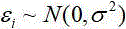
obey a normal distribution. In
formula 1
,
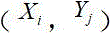
Are all unknown, according to the sample data pair
And
the statistics are carried out, and the statistics are carried out,
and
is estimated as
And
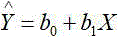
establishing a unary linear equation:
generally, what is desired is
And
should enable observation of each sample
The deviation from the fitted straight line is as small as possible.
It is noted that, herein, relational terms such as first and second, and the like may be used solely to distinguish one entity or action from another entity or action without necessarily requiring or implying any actual such relationship or order between such entities or actions. Also, the terms "comprises," "comprising," or any other variation thereof, are intended to cover a non-exclusive inclusion, such that a process, method, article, or apparatus that comprises a list of elements does not include only those elements but may include other elements not expressly listed or inherent to such process, method, article, or apparatus. Without further limitation. The use of the phrase "comprising one of the elements does not exclude the presence of other like elements in the process, method, article, or apparatus that comprises the element.
Although embodiments of the present invention have been shown and described, it will be appreciated by those skilled in the art that changes, modifications, substitutions and alterations can be made in these embodiments without departing from the principles and spirit of the invention, the scope of which is defined in the appended claims and their equivalents.