CN114160661A - A die-casting mold that can automatically collect blanking materials - Google Patents
A die-casting mold that can automatically collect blanking materials Download PDFInfo
- Publication number
- CN114160661A CN114160661A CN202111337984.9A CN202111337984A CN114160661A CN 114160661 A CN114160661 A CN 114160661A CN 202111337984 A CN202111337984 A CN 202111337984A CN 114160661 A CN114160661 A CN 114160661A
- Authority
- CN
- China
- Prior art keywords
- die
- casting
- plate
- stamping
- slide
- Prior art date
- Legal status (The legal status is an assumption and is not a legal conclusion. Google has not performed a legal analysis and makes no representation as to the accuracy of the status listed.)
- Pending
Links
- 238000004512 die casting Methods 0.000 title claims abstract description 80
- 239000000463 material Substances 0.000 title claims description 27
- 238000005520 cutting process Methods 0.000 claims abstract description 28
- 238000003825 pressing Methods 0.000 claims description 22
- 238000004080 punching Methods 0.000 claims description 11
- 239000007787 solid Substances 0.000 claims 1
- 238000005058 metal casting Methods 0.000 abstract description 8
- 230000010354 integration Effects 0.000 abstract description 2
- 238000003754 machining Methods 0.000 abstract 1
- 239000002184 metal Substances 0.000 description 9
- 239000002994 raw material Substances 0.000 description 7
- 239000002699 waste material Substances 0.000 description 7
- 238000004519 manufacturing process Methods 0.000 description 4
- 238000010586 diagram Methods 0.000 description 2
- 238000000034 method Methods 0.000 description 2
- 230000009286 beneficial effect Effects 0.000 description 1
Images


Classifications
-
- B—PERFORMING OPERATIONS; TRANSPORTING
- B21—MECHANICAL METAL-WORKING WITHOUT ESSENTIALLY REMOVING MATERIAL; PUNCHING METAL
- B21D—WORKING OR PROCESSING OF SHEET METAL OR METAL TUBES, RODS OR PROFILES WITHOUT ESSENTIALLY REMOVING MATERIAL; PUNCHING METAL
- B21D28/00—Shaping by press-cutting; Perforating
- B21D28/24—Perforating, i.e. punching holes
- B21D28/34—Perforating tools; Die holders
-
- B—PERFORMING OPERATIONS; TRANSPORTING
- B21—MECHANICAL METAL-WORKING WITHOUT ESSENTIALLY REMOVING MATERIAL; PUNCHING METAL
- B21D—WORKING OR PROCESSING OF SHEET METAL OR METAL TUBES, RODS OR PROFILES WITHOUT ESSENTIALLY REMOVING MATERIAL; PUNCHING METAL
- B21D43/00—Feeding, positioning or storing devices combined with, or arranged in, or specially adapted for use in connection with, apparatus for working or processing sheet metal, metal tubes or metal profiles; Associations therewith of cutting devices
- B21D43/28—Associations of cutting devices therewith
Landscapes
- Engineering & Computer Science (AREA)
- Mechanical Engineering (AREA)
- Punching Or Piercing (AREA)
Abstract
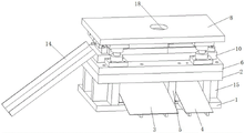
The invention discloses a die-casting die capable of automatically collecting blanking, which comprises a base and a lower cushion plate, wherein a gap is formed between the base and the lower cushion plate, a first collecting slide and a second collecting slide are arranged in the gap, a baffle is arranged between the first collecting slide and the second collecting slide, the upper end and the lower end of the baffle are respectively connected with the lower cushion plate and the base, an upper cushion plate is arranged on the upper end surface of the lower cushion plate, a top plate is arranged above the upper cushion plate, guide columns are fixedly arranged at four corners of the upper cushion plate and movably connected with guide sleeves on the top plate, a die set fixing plate is fixedly arranged on the upper cushion plate, and a stamping die set, a die-casting die set and a cutting die set are sequentially arranged on the die set fixing plate from right to left. The metal casting blanking device has the advantages of simple structure, ingenious design, integration of stamping, die casting and cutting, small occupied area, great improvement of the metal casting machining efficiency, automatic collection of blanking and reduction of the labor intensity of workers.
Description
Technical Field
The invention relates to the technical field of die-casting dies, in particular to a die-casting die capable of automatically collecting blanking.
Background
The metal casting with the metal flanging and the hole sites is usually required to be cold-pressed and cast into the shape of the flanging in the forming process, a finished product is obtained by punching through a punching machine, the processing technology is complex, the manual labor intensity is high, the occupied area of a plurality of devices is large, and the processing efficiency is greatly reduced. Therefore, there is a need for improvement of the existing die casting mold.
Disclosure of Invention
The invention aims to provide a die-casting die capable of automatically collecting blanking, which has the advantages of simple structure, ingenious design, integration of stamping, die-casting and cutting, small occupied area, great improvement on the processing efficiency of metal castings, automatic collection of blanking, reduction in labor intensity of workers and capability of solving the problems brought forward by the technical background.
In order to achieve the purpose, the invention provides the following technical scheme: the utility model provides a die casting die of automatically collecting blanking, this die casting die includes base and lower bolster, be provided with the clearance between base and the lower bolster, be provided with the first slide and the second slide that gathers materials in this clearance, the first slide and the second that gathers materials is provided with the baffle between the slide that gathers materials, the upper and lower both ends of baffle are connected with lower bolster and base respectively, the up end of lower bolster is provided with the upper padding plate, the top of upper padding plate is provided with the roof, and the four corners fixed mounting of upper padding plate has the guide pillar, guide pin bushing swing joint on guide pillar and the roof, it has the module fixed plate to go back fixed mounting on the upper padding plate, install punching press module, die-casting module and cut the module in proper order from right side to left side on the module fixed plate, the one side of cutting the module is provided with the third slide that gathers materials.
Preferably, the die-casting die further comprises a supporting plate, the supporting plate is located on one side of the first collecting slide and one side of the second collecting slide, and the upper end and the lower end of the supporting plate are respectively connected with the lower base plate and the base.
Preferably, all set up the through-hole that supplies the product to fall into on lower bolster, upper padding plate and the module fixed plate, the position of through-hole corresponds with the position of first slide and the second slide that gathers materials.
Preferably, the first collecting slide, the second collecting slide and the third collecting slide form an included angle of 30 degrees with the horizontal plane.
Preferably, a fixing ring for connecting the press is arranged on the top plate, and the fixing ring is positioned in the middle of the top plate.
Preferably, a material feeding device is arranged at one end, close to the stamping module, of the module fixing plate and is composed of two feeding units, each feeding unit comprises a fixing block fixedly installed on the module fixing plate and a fixing shaft fixedly installed on the fixing block, a sliding roller is sleeved on the outer side of the fixing shaft and can slide along the radial direction of the fixing shaft, a limiting cap is arranged at one end, far away from the fixing block, of the fixing shaft, and the limiting cap and the fixing shaft are integrally formed.
Preferably, the stamping module comprises a stamping upper pressing plate, a stamping lower pressing plate and a stamping needle fixing plate, the number of the stamping needle fixing plates is four, each stamping needle is fixedly mounted on the stamping needle fixing plate, and one end, far away from the stamping needle fixing plate, of each stamping needle penetrates through the stamping upper pressing plate and then is in contact connection with a stamping die on the stamping lower pressing plate.
Preferably, the die-casting module includes die-casting top board, die-casting bottom board and die-casting fixed plate, fixed mounting has die casting die on the die-casting fixed plate, die casting die keeps away from die-casting fixed plate one terminal surface and runs through behind the die-casting top board with die cavity contact connection on the die-casting bottom board.
Preferably, the die-casting upper pressure plate is provided with a die hole for the die-casting die to penetrate through, and the size of the die hole is slightly larger than that of the die groove.
Preferably, the cutting module comprises a cutter fixing plate fixedly connected with the top plate, a cutter fixedly mounted on the cutter fixing plate and a cutting backing plate arranged below the cutter, the cutting backing plate and the cutter are arranged at intervals, and the cutting backing plate is fixedly mounted on the module fixing plate.
Compared with the prior art, the invention has the following beneficial effects:
1. the die-casting die capable of automatically collecting blanking provided by the invention has the advantages that the whole structure is simple, the design is ingenious and reasonable, the punching module, the die-casting module and the cutting module are sequentially arranged on the module fixing plate from right to left, a metal casting can be punched, die-cast and cut at one time, the processing efficiency is greatly improved, the occupied area is saved, the punched scraps and the cut scraps can be collected through the second collecting slide and the third collecting slide, the die-cast metal casting can be collected through the first collecting slide, the automatic collection blanking is realized, and the labor intensity of workers is reduced.
2. According to the invention, the material feeding device is arranged on the module fixing plate close to one end of the stamping module and consists of two feeding units, and automatic feeding is realized through the matching of the two feeding units, so that the labor cost is saved, automatic production is realized, and the production and processing efficiency is improved.
Drawings
FIG. 1 is an exploded view of the present invention;
FIG. 2 is an overall structural view of the present invention;
FIG. 3 is an exploded view of the stamping die set of the present invention;
FIG. 4 is an exploded view of the die cast die set of the present invention;
FIG. 5 is a block diagram of a cutting module according to the present invention;
fig. 6 is a block diagram of the feed unit of the present invention.
The reference numerals and names in the figures are as follows:
1. a base; 2. a lower base plate; 3. a first collection slide; 4. a second collection slide; 5. a baffle plate; 6. an upper base plate; 7. a guide post; 8. a top plate; 9. a guide sleeve; 10. a module fixing plate; 11. a stamping module; 111. stamping an upper pressing plate; 112. punching a lower pressing plate; 113. a punching needle fixing plate; 114. punching a needle; 115. stamping a die; 12. die-casting die set; 121. die-casting an upper pressure plate; 122. die-casting a lower pressing plate; 123. a die fixing plate; 124. a die-casting die; 125. a die cavity; 126. a die hole; 13. a cutting module; 131. a cutter fixing plate; 132. a cutter; 133. cutting the base plate; 14. a third collection slide; 15. a support plate; 16. a through hole; 17. a feeding unit; 171. a fixed block; 172. a fixed shaft; 173. a sliding roller; 174. a limiting cap; 18. and (4) fixing the ring.
Detailed Description
The technical solutions in the embodiments of the present invention will be clearly and completely described below with reference to the drawings in the embodiments of the present invention, and it is obvious that the described embodiments are only a part of the embodiments of the present invention, and not all of the embodiments. All other embodiments, which can be derived by a person skilled in the art from the embodiments given herein without making any creative effort, shall fall within the protection scope of the present invention.
In the description of the embodiments of the present invention, it should be understood that the terms "length", "width", "up", "down", "front", "back", "left", "right", "vertical", "horizontal", "top", "bottom", "inner", "outer", etc. indicate orientations or positional relationships based on those shown in the drawings, and are only for convenience in describing the embodiments of the present invention and simplifying the description, but do not indicate or imply that the device or element referred to must have a particular orientation, be constructed and operated in a particular orientation, and thus, should not be construed as limiting the present invention. Furthermore, the terms "first", "second" and "first" are used for descriptive purposes only and are not to be construed as indicating or implying relative importance or implicitly indicating the number of technical features indicated. Thus, a feature defined as "first" or "second" may explicitly or implicitly include one or more of that feature. In the description of the embodiments of the present invention, "a plurality" means two or more unless specifically limited otherwise.
In the embodiments of the present invention, unless otherwise explicitly specified or limited, the terms "mounted," "connected," "fixed," and the like are to be construed broadly, e.g., as being fixedly connected, detachably connected, or integrated; can be mechanically or electrically connected; either directly or indirectly through intervening media, either internally or in any other relationship. Specific meanings of the above terms in the embodiments of the present invention can be understood by those of ordinary skill in the art according to specific situations.
Referring to fig. 1 to fig. 2, an embodiment of the present invention includes: the die casting die capable of automatically collecting blanking comprises a base 1 and a lower backing plate 2, wherein a gap is formed between the base 1 and the lower backing plate 2, a first collecting slide 3 and a second collecting slide 4 are arranged in the gap, the first collecting slide 3 and the second collecting slide 4 are respectively used for collecting metal casting finished products and punching scraps, a baffle 5 is arranged between the first collecting slide 3 and the second collecting slide 4, the upper end and the lower end of the baffle 5 are respectively connected with the lower backing plate 2 and the base 1, an upper backing plate 6 is arranged on the upper end face of the lower backing plate 2, a top plate 8 is arranged above the upper backing plate 6, guide pillars 7 are fixedly arranged at four corners of the upper backing plate 6, the guide pillars 7 are movably connected with guide sleeves 9 on the top plate 8, a module fixing plate 10 is further fixedly arranged on the upper backing plate 6, and stamping modules 11, a stamping die and a stamping die are sequentially arranged on the module fixing plate 10 from right to left, Die-casting module 12 with cut module 13, product raw material panel punches a hole through punching press module 11 in proper order, through die-casting module 12 die-casting turn-ups, cuts the waste material through cutting module 13 and collects, collect punching press, die-casting and cut in design as an organic whole, area is little, has improved the efficiency of metal casting processing greatly, one side of cutting module 13 is provided with the third slide 14 that gathers materials, the third slide 14 that gathers materials is used for collecting the waste material after cutting, die-casting die still includes backup pad 15, backup pad 15 is located first slide 3 that gathers materials and second slide 4 one side that gathers materials, and backup pad 15's upper and lower both ends are connected with lower bolster 2 and base 1 respectively.
Specifically, all set up the through-hole 16 that supplies the product to fall into on lower bolster 2, upper padding plate 6 and the module fixed plate 10, the position of through-hole 16 corresponds with the position of first slide 3 and the second slide 4 that gathers materials.
Specifically, the first collecting slide 3, the second collecting slide 4 and the third collecting slide 14 are arranged at an included angle of 30 degrees with the horizontal plane, so that the collecting and blanking are facilitated.
Specifically, a fixing ring 18 for connecting the press is arranged on the top plate 8, and the fixing ring 18 is located in the middle of the top plate 8.
Referring to fig. 3, the stamping module 11 in the drawing includes four stamping upper press plates 111, four stamping lower press plates 112, and four stamping pin fixing plates 113, a stamping pin 114 is fixedly mounted on each stamping pin fixing plate 113, one end of the stamping pin 114, which is far away from the stamping pin fixing plate 113, penetrates through the stamping upper press plate 111 and then is in contact connection with a stamping die 115 on the stamping lower press plate 112, and the stamping pin 114 and the stamping die 115 are matched to punch a metal raw material to be die-cast.
Referring to fig. 4, the die casting module 12 in the drawing includes a die casting upper pressing plate 121, a die casting lower pressing plate 122 and a die fixing plate 123, a die casting mold 124 is fixedly mounted on the die fixing plate 123, and an end surface of the die casting mold 124, which is far away from the die fixing plate 123, penetrates through the die casting upper pressing plate 121 and then is in contact connection with a mold cavity 125 on the die casting lower pressing plate 122.
Specifically, a die hole 126 for a die casting mold 124 to penetrate through is formed in the die casting upper pressing plate 121, the size of the die hole 126 is slightly larger than that of the die groove 125, when a metal raw material to be die-cast between the die casting upper pressing plate 121 and the die casting lower pressing plate 122 enters the die casting mold 124, the die casting mold 124 presses down to form a die casting metal piece, the formed metal piece forms a flanging between the die hole 126 and the die groove 125, and a formed product is collected by the first collecting slide 3.
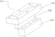
Referring to fig. 5, the cutting module 13 includes a cutter fixing plate 131 fixedly connected to the top plate 8, a cutter 132 fixedly mounted on the cutter fixing plate 131, and a cutting pad 133 disposed below the cutter 132, the cutting pad 133 and the cutter 132 are disposed at an interval, the cutting pad 133 is fixedly mounted on the module fixing plate 10, the die-cast waste is cut by the cutter 132, and the cut waste is collected by the third collecting slide 14.
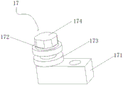
Referring to fig. 1 and 6, a material feeding device is arranged at one end of the module fixing plate 10 close to the stamping module 11, the material feeding device is composed of two feeding units 17, each feeding unit 17 includes a fixing block 171 fixedly mounted on the module fixing plate 10 and a fixing shaft 172 fixedly mounted on the fixing block 171, a sliding roller 173 is sleeved on the outer side of the fixing shaft 172, the sliding roller 173 can slide along the radial direction of the fixing shaft 172, a limiting cap 174 is arranged at one end of the fixing shaft 172 far from the fixing block 171, the limiting cap 174 and the fixing shaft 172 are integrally formed, automatic feeding is achieved through cooperation of the two feeding units 17, labor cost is saved, automatic production is achieved, and production and processing efficiency is improved.
In the working process of the die-casting die, the die-casting die is fixedly arranged on a press machine, sheet metal raw materials are automatically fed by the cooperation of two feeding units 17 on a material feeding device and sequentially pass through a stamping die set 11, a die-casting die set 12 and a cutting die set 13, a stamping pin 114 on the stamping die set 11 is matched with a stamping die 115 to punch a metal raw material to be die-cast, the die-casting die set 12 performs die-casting flanging on the punched metal raw material, a formed product is collected by a first collecting slide 3, when waste materials of the metal raw material pass through the cutting die set 13, the waste materials are cut by a cutter 132 on the cutting die set 13, and the cut waste materials are collected by a third collecting slide 14.
It will be evident to those skilled in the art that the invention is not limited to the details of the foregoing illustrative embodiments, and that the present invention may be embodied in other specific forms without departing from the spirit or essential attributes thereof. The present embodiments are therefore to be considered in all respects as illustrative and not restrictive, the scope of the invention being indicated by the appended claims rather than by the foregoing description, and all changes which come within the meaning and range of equivalency of the claims are therefore intended to be embraced therein. Any reference sign in a claim should not be construed as limiting the claim concerned.
Claims (10)
1. The utility model provides a but die casting die of automatic collection blanking, includes base (1) and lower backing plate (2), its characterized in that: a gap is arranged between the base (1) and the lower backing plate (2), a first material collecting slide (3) and a second material collecting slide (4) are arranged in the gap, a baffle (5) is arranged between the first material collecting slide (3) and the second material collecting slide (4), the upper end and the lower end of the baffle (5) are respectively connected with the lower backing plate (2) and the base (1), an upper backing plate (6) is arranged on the upper end face of the lower backing plate (2), a top plate (8) is arranged above the upper backing plate (6), guide posts (7) are fixedly arranged at four corners of the upper backing plate (6), the guide posts (7) are movably connected with guide sleeves (9) on the top plate (8), a module fixing plate (10) is fixedly arranged on the upper backing plate (6), and a stamping module (11), a die casting module (12) and a cutting module (13) are sequentially arranged on the module fixing plate (10) from right to left, and a third collecting slide (14) is arranged on one side of the cutting module (13).
2. The die-casting die capable of automatically collecting blanking as claimed in claim 1, wherein: still include backup pad (15), backup pad (15) are located first slide (3) and the second slide (4) one side of gathering materials, and the upper and lower both ends of backup pad (15) are connected with lower bolster (2) and base (1) respectively.
3. The die-casting die capable of automatically collecting blanking as claimed in claim 1, wherein: all set up through-hole (16) that supply the product to fall into on lower bolster (2), upper padding plate (6) and module fixed plate (10), the position of through-hole (16) is corresponding with the position of first slide (3) and the second slide (4) that gathers materials.
4. The die-casting die capable of automatically collecting blanking as claimed in claim 1, wherein: the first material collecting slide (3), the second material collecting slide (4) and the third material collecting slide (14) are arranged at an included angle of 30 degrees with the horizontal plane.
5. The die-casting die capable of automatically collecting blanking as claimed in claim 1, wherein: be provided with solid fixed ring (18) that are used for connecting the press on roof (8), gu fixed ring (18) are located the positive centre department of roof (8).
6. The die-casting die capable of automatically collecting blanking as claimed in claim 1, wherein: be provided with material feeding device near punching press module (11) one end on module fixed plate (10), material feeding device comprises two feeding units (17), every feeding unit (17) are including fixed block (171) and fixed axle (172) of fixed mounting on fixed block (171) of fixed mounting (10), the outside cover of fixed axle (172) is equipped with slip gyro wheel (173), slip gyro wheel (173) can be followed and slided on the radial direction of fixed axle (172), fixed axle (172) are kept away from fixed block (171) one end and are provided with spacing cap (174), spacing cap (174) with fixed axle (172) integrated into one piece.
7. The die-casting die capable of automatically collecting blanking as claimed in claim 1, wherein: the stamping die set (11) comprises a stamping upper pressing plate (111), a stamping lower pressing plate (112) and a stamping needle fixing plate (113), wherein four stamping needle fixing plates (113) are arranged, each stamping needle fixing plate (113) is fixedly provided with a stamping needle (114), and one end, far away from the stamping needle fixing plate (113), of the stamping needle (114) penetrates through the stamping upper pressing plate (111) and then is in contact connection with a stamping die (115) on the stamping lower pressing plate (112).
8. The die-casting die capable of automatically collecting blanking as claimed in claim 1, wherein: the die-casting module (12) comprises a die-casting upper pressing plate (121), a die-casting lower pressing plate (122) and a die-casting fixing plate (123), a die-casting die (124) is fixedly mounted on the die-casting fixing plate (123), and one end face, far away from the die-casting fixing plate (123), of the die-casting die (124) penetrates through the die-casting upper pressing plate (121) and then is in contact connection with a die cavity (125) in the die-casting lower pressing plate (122).
9. The die-casting die capable of automatically collecting blanking as claimed in claim 8, wherein: and a die hole (126) for a die-casting die (124) to penetrate through is formed in the die-casting upper pressure plate (121), and the size of the die hole (126) is slightly larger than that of the die groove (125).
10. The die-casting die capable of automatically collecting blanking as claimed in claim 1, wherein: the cutting module (13) comprises a cutter fixing plate (131) fixedly connected with the top plate (8), a cutter (132) fixedly installed on the cutter fixing plate (131) and a cutting backing plate (133) arranged below the cutter (132), the cutting backing plate (133) and the cutter (132) are arranged at intervals, and the cutting backing plate (133) is fixedly installed on the module fixing plate (10).
Priority Applications (1)
| Application Number | Priority Date | Filing Date | Title |
|---|---|---|---|
| CN202111337984.9A CN114160661A (en) | 2021-11-12 | 2021-11-12 | A die-casting mold that can automatically collect blanking materials |
Applications Claiming Priority (1)
| Application Number | Priority Date | Filing Date | Title |
|---|---|---|---|
| CN202111337984.9A CN114160661A (en) | 2021-11-12 | 2021-11-12 | A die-casting mold that can automatically collect blanking materials |
Publications (1)
| Publication Number | Publication Date |
|---|---|
| CN114160661A true CN114160661A (en) | 2022-03-11 |
Family
ID=80479182
Family Applications (1)
| Application Number | Title | Priority Date | Filing Date |
|---|---|---|---|
| CN202111337984.9A Pending CN114160661A (en) | 2021-11-12 | 2021-11-12 | A die-casting mold that can automatically collect blanking materials |
Country Status (1)
| Country | Link |
|---|---|
| CN (1) | CN114160661A (en) |
Citations (12)
| Publication number | Priority date | Publication date | Assignee | Title |
|---|---|---|---|---|
| JPS52107569A (en) * | 1976-03-06 | 1977-09-09 | Sony Corp | Device for bending and cutting electronic parts |
| CN102601241A (en) * | 2012-03-31 | 2012-07-25 | 重庆至信实业有限公司 | Blanking die for rear beam of automobile front floor |
| CN103567290A (en) * | 2012-07-30 | 2014-02-12 | 苏州飞宇精密科技股份有限公司 | Blanking and flanging integrated composite precision die |
| CN104475584A (en) * | 2014-12-23 | 2015-04-01 | 无锡微研有限公司 | Mold for ensuring blanking flanging hole punching concentricity |
| CN205798149U (en) * | 2016-05-17 | 2016-12-14 | 昆山岳众模具有限公司 | A kind of automobile progressive die with drawing mechanism |
| CN206009568U (en) * | 2016-08-03 | 2017-03-15 | 宁波贤丰汽车零部件有限公司 | A kind of stamping continuous die structure for manufacturing becket |
| CN208527839U (en) * | 2018-07-13 | 2019-02-22 | 中山市伟琪电器有限公司 | A kind of progressive die making compressor pair muffler |
| CN209061968U (en) * | 2018-11-06 | 2019-07-05 | 合肥景岭自动化科技有限公司 | A kind of stamping die with formed punch |
| CN210080523U (en) * | 2019-07-01 | 2020-02-18 | 东莞市宝弘五金模具有限公司 | A metal fitting stamping die |
| CN211276229U (en) * | 2019-12-19 | 2020-08-18 | 浙江龙游力辉电子科技有限公司 | Forming die for producing LED lamp support |
| CN211437840U (en) * | 2020-01-15 | 2020-09-08 | 杭州瑶天滑轨有限公司 | Slide rail raw and other materials feeder |
| CN113523062A (en) * | 2021-06-15 | 2021-10-22 | 宁波如意股份有限公司 | A die that can continuously punch and cut profiles |
-
2021
- 2021-11-12 CN CN202111337984.9A patent/CN114160661A/en active Pending
Patent Citations (12)
| Publication number | Priority date | Publication date | Assignee | Title |
|---|---|---|---|---|
| JPS52107569A (en) * | 1976-03-06 | 1977-09-09 | Sony Corp | Device for bending and cutting electronic parts |
| CN102601241A (en) * | 2012-03-31 | 2012-07-25 | 重庆至信实业有限公司 | Blanking die for rear beam of automobile front floor |
| CN103567290A (en) * | 2012-07-30 | 2014-02-12 | 苏州飞宇精密科技股份有限公司 | Blanking and flanging integrated composite precision die |
| CN104475584A (en) * | 2014-12-23 | 2015-04-01 | 无锡微研有限公司 | Mold for ensuring blanking flanging hole punching concentricity |
| CN205798149U (en) * | 2016-05-17 | 2016-12-14 | 昆山岳众模具有限公司 | A kind of automobile progressive die with drawing mechanism |
| CN206009568U (en) * | 2016-08-03 | 2017-03-15 | 宁波贤丰汽车零部件有限公司 | A kind of stamping continuous die structure for manufacturing becket |
| CN208527839U (en) * | 2018-07-13 | 2019-02-22 | 中山市伟琪电器有限公司 | A kind of progressive die making compressor pair muffler |
| CN209061968U (en) * | 2018-11-06 | 2019-07-05 | 合肥景岭自动化科技有限公司 | A kind of stamping die with formed punch |
| CN210080523U (en) * | 2019-07-01 | 2020-02-18 | 东莞市宝弘五金模具有限公司 | A metal fitting stamping die |
| CN211276229U (en) * | 2019-12-19 | 2020-08-18 | 浙江龙游力辉电子科技有限公司 | Forming die for producing LED lamp support |
| CN211437840U (en) * | 2020-01-15 | 2020-09-08 | 杭州瑶天滑轨有限公司 | Slide rail raw and other materials feeder |
| CN113523062A (en) * | 2021-06-15 | 2021-10-22 | 宁波如意股份有限公司 | A die that can continuously punch and cut profiles |
Similar Documents
| Publication | Publication Date | Title |
|---|---|---|
| CN105013953A (en) | High-accuracy punching and cutting device | |
| CN103586334A (en) | Metal glazed tile processing device | |
| CN210450626U (en) | Stamping die for solar component connecting box cover | |
| CN210098710U (en) | Waste material shaping device is cut in aluminium die casting punching a hole | |
| CN114160661A (en) | A die-casting mold that can automatically collect blanking materials | |
| CN211990548U (en) | Novel stamping die | |
| CN204867102U (en) | High accuracy cutting device that punches a hole | |
| CN214639817U (en) | Left and right swing arm front mounting bracket stamping device | |
| CN219112678U (en) | Stamping die of compressor shell | |
| CN216065196U (en) | Stamping die for sheet metal part of seat back plate | |
| CN215431091U (en) | Rear seat lower mounting bracket stamping device | |
| CN215391997U (en) | End cover side cut mould that punches a hole | |
| CN212792683U (en) | Automobile spare and accessory part multistation stamping die | |
| CN203508749U (en) | Processing device of metal glazed tiles | |
| CN216606755U (en) | Small-size sheet metal component forming device that buckles | |
| CN220297968U (en) | Multifunctional die-cutting tool station suitable for paper bag processing equipment | |
| CN221291628U (en) | Device suitable for processing large-size products of die cutting machine | |
| CN223557037U (en) | A continuous stamping die for battery connectors | |
| CN213944543U (en) | Combined die for stamping automobile parts | |
| CN221021755U (en) | Dot matrix mesh stamping device | |
| CN217831497U (en) | Continuous stamping die of mesh | |
| CN112296198A (en) | Positioning and punching device for metal plate machining | |
| CN220591263U (en) | Special die for punching thin seams by thick materials | |
| CN220028391U (en) | Perpendicular cut-out press of car sheet metal component | |
| CN219837898U (en) | Universal single-punch die for Mylar sheet |
Legal Events
| Date | Code | Title | Description |
|---|---|---|---|
| PB01 | Publication | ||
| PB01 | Publication | ||
| SE01 | Entry into force of request for substantive examination | ||
| SE01 | Entry into force of request for substantive examination | ||
| RJ01 | Rejection of invention patent application after publication | ||
| RJ01 | Rejection of invention patent application after publication |
Application publication date: 20220311 |