CN114112690B - In-situ loess tensile strength testing device and testing method - Google Patents
In-situ loess tensile strength testing device and testing method Download PDFInfo
- Publication number
- CN114112690B CN114112690B CN202111381048.8A CN202111381048A CN114112690B CN 114112690 B CN114112690 B CN 114112690B CN 202111381048 A CN202111381048 A CN 202111381048A CN 114112690 B CN114112690 B CN 114112690B
- Authority
- CN
- China
- Prior art keywords
- hole
- cutting
- wall
- rigid instrument
- instrument shell
- Prior art date
- Legal status (The legal status is an assumption and is not a legal conclusion. Google has not performed a legal analysis and makes no representation as to the accuracy of the status listed.)
- Expired - Fee Related
Links
- 238000012360 testing method Methods 0.000 title claims abstract description 51
- 238000011065 in-situ storage Methods 0.000 title claims abstract description 24
- 238000005520 cutting process Methods 0.000 claims abstract description 68
- 239000002689 soil Substances 0.000 claims abstract description 42
- 230000007246 mechanism Effects 0.000 claims description 48
- 230000035515 penetration Effects 0.000 claims description 37
- 230000000149 penetrating effect Effects 0.000 claims description 16
- 230000009471 action Effects 0.000 claims description 9
- 239000010720 hydraulic oil Substances 0.000 claims description 6
- 238000006243 chemical reaction Methods 0.000 claims description 5
- 230000036346 tooth eruption Effects 0.000 claims description 3
- 238000002347 injection Methods 0.000 claims 7
- 239000007924 injection Substances 0.000 claims 7
- 230000001105 regulatory effect Effects 0.000 claims 5
- 238000010998 test method Methods 0.000 claims 1
- 238000000034 method Methods 0.000 abstract description 16
- 230000008569 process Effects 0.000 abstract description 12
- 238000004519 manufacturing process Methods 0.000 abstract description 2
- 239000000463 material Substances 0.000 abstract description 2
- 239000002184 metal Substances 0.000 abstract description 2
- 238000005265 energy consumption Methods 0.000 abstract 1
- 238000010586 diagram Methods 0.000 description 7
- 230000000712 assembly Effects 0.000 description 5
- 238000000429 assembly Methods 0.000 description 5
- 238000010276 construction Methods 0.000 description 4
- 238000005336 cracking Methods 0.000 description 3
- 239000011435 rock Substances 0.000 description 3
- 230000009286 beneficial effect Effects 0.000 description 2
- 238000006073 displacement reaction Methods 0.000 description 2
- 238000005259 measurement Methods 0.000 description 2
- 238000005096 rolling process Methods 0.000 description 2
- 230000007480 spreading Effects 0.000 description 2
- 238000003892 spreading Methods 0.000 description 2
- 238000004873 anchoring Methods 0.000 description 1
- 230000008859 change Effects 0.000 description 1
- 230000009977 dual effect Effects 0.000 description 1
- 238000012986 modification Methods 0.000 description 1
- 230000004048 modification Effects 0.000 description 1
- 230000004044 response Effects 0.000 description 1
- 230000008054 signal transmission Effects 0.000 description 1
- 238000009864 tensile test Methods 0.000 description 1
- 238000003466 welding Methods 0.000 description 1
Images


Classifications
-
- G—PHYSICS
- G01—MEASURING; TESTING
- G01N—INVESTIGATING OR ANALYSING MATERIALS BY DETERMINING THEIR CHEMICAL OR PHYSICAL PROPERTIES
- G01N3/00—Investigating strength properties of solid materials by application of mechanical stress
- G01N3/08—Investigating strength properties of solid materials by application of mechanical stress by applying steady tensile or compressive forces
- G01N3/10—Investigating strength properties of solid materials by application of mechanical stress by applying steady tensile or compressive forces generated by pneumatic or hydraulic pressure
-
- G—PHYSICS
- G01—MEASURING; TESTING
- G01N—INVESTIGATING OR ANALYSING MATERIALS BY DETERMINING THEIR CHEMICAL OR PHYSICAL PROPERTIES
- G01N3/00—Investigating strength properties of solid materials by application of mechanical stress
- G01N3/02—Details
-
- G—PHYSICS
- G01—MEASURING; TESTING
- G01N—INVESTIGATING OR ANALYSING MATERIALS BY DETERMINING THEIR CHEMICAL OR PHYSICAL PROPERTIES
- G01N2203/00—Investigating strength properties of solid materials by application of mechanical stress
- G01N2203/0001—Type of application of the stress
- G01N2203/0005—Repeated or cyclic
-
- G—PHYSICS
- G01—MEASURING; TESTING
- G01N—INVESTIGATING OR ANALYSING MATERIALS BY DETERMINING THEIR CHEMICAL OR PHYSICAL PROPERTIES
- G01N2203/00—Investigating strength properties of solid materials by application of mechanical stress
- G01N2203/0014—Type of force applied
- G01N2203/0016—Tensile or compressive
- G01N2203/0017—Tensile
-
- G—PHYSICS
- G01—MEASURING; TESTING
- G01N—INVESTIGATING OR ANALYSING MATERIALS BY DETERMINING THEIR CHEMICAL OR PHYSICAL PROPERTIES
- G01N2203/00—Investigating strength properties of solid materials by application of mechanical stress
- G01N2203/003—Generation of the force
- G01N2203/0042—Pneumatic or hydraulic means
- G01N2203/0048—Hydraulic means
Landscapes
- Physics & Mathematics (AREA)
- Health & Medical Sciences (AREA)
- Life Sciences & Earth Sciences (AREA)
- Chemical & Material Sciences (AREA)
- Analytical Chemistry (AREA)
- Biochemistry (AREA)
- General Health & Medical Sciences (AREA)
- General Physics & Mathematics (AREA)
- Immunology (AREA)
- Pathology (AREA)
- Investigating Strength Of Materials By Application Of Mechanical Stress (AREA)
Abstract
Description
技术领域technical field
本发明属于岩土工程测试领域,涉及一种原位黄土抗拉强度测试装置及测试方法。The invention belongs to the field of geotechnical engineering testing, and relates to an in-situ loess tensile strength testing device and a testing method.
背景技术Background technique
近年来,在黄土高原地区大规模的治沟造地、平山造城工程建设如火如荼,但也存在着黄土工程失稳灾变的风险和安全隐患,严重影响工程建设的进程和国家重大战略的实施,迫切需要科学应对。对土体强度的准确测试是工程建设推进和维持工程稳定性的前提条件。In recent years, the construction of large-scale ditch land reclamation and flat mountain city construction in the Loess Plateau area is in full swing, but there are also risks of loess engineering instability and disasters and potential safety hazards, which seriously affect the progress of engineering construction and the implementation of major national strategies. A scientific response is urgently needed. Accurate testing of soil strength is a prerequisite for advancing engineering construction and maintaining engineering stability.
岩土体原位测试是在岩土体的天然状态下,通过对切割的相应大小尺寸的试样进行各种测试以获得可靠的岩土体物理、力学等指标,原位测试是岩土体工程勘察的重要手段。在传统的岩土工程试验中,由于黄土抗拉强度较小,且相对于其他土壤强度参数难以测量而常被忽略。黄土地区边坡失稳裂滑的灾变过程多始于边坡坡体或者坡顶的拉张开裂。黄土地区灾害的孕生机理表明,黄土的抗拉强度特性是影响黄土边坡稳定性的重要因素,不可忽略。The in-situ test of rock and soil is in the natural state of the rock and soil, and various tests are carried out on the cut samples of corresponding sizes to obtain reliable physical and mechanical indicators of the rock and soil. An important means of engineering survey. In traditional geotechnical engineering tests, loess is often ignored due to its small tensile strength and difficulty in measuring relative to other soil strength parameters. The catastrophic process of slope instability, cracking and sliding in loess areas usually begins with the stretching and cracking of the slope body or slope top. The generation mechanism of disasters in loess areas shows that the tensile strength of loess is an important factor affecting the stability of loess slopes and cannot be ignored.
目前,无侧限贯入试验(轴向压裂试验)在对黄土抗拉强度室内测试中应用较多,而且无侧限贯入试验往往会造成最薄弱面的破坏,从而能得到更真实的抗拉强度值。然而,黄土质地疏松,样品在采集、搬运过程中易扰动,且此时的土样在测试过程中与天然状态下的含水率等土体性质存在一定的偏差,室内无侧限贯入试验测试误差大,测试精度低;现场原位测试是最为直接、最为可靠的获取黄土边坡力学特征信息的方法,但目前针对孔内原位抗拉测试的设备研发仍然较少,如何精准捕获土体内部关键部位的拉裂变形特征和抗拉强度特性仍然是未破解的难题。At present, the unconfined penetration test (axial fracturing test) is widely used in the indoor testing of the tensile strength of loess, and the unconfined penetration test often causes damage to the weakest surface, so that a more realistic Tensile strength value. However, the loess is loose in texture, and the samples are easily disturbed during the collection and transportation process, and there is a certain deviation between the soil properties such as moisture content and other soil properties in the natural state during the test process, and the indoor unconfined penetration test test The error is large and the test accuracy is low; on-site in-situ testing is the most direct and reliable method to obtain the mechanical characteristic information of loess slopes, but there are still few equipments for in-situ tensile testing in holes. How to accurately capture the soil The cracking deformation characteristics and tensile strength characteristics of internal key parts are still unsolved problems.
发明内容Contents of the invention
针对传统的室内测试手段测试误差较大,受外界环境明显影响,难以准确获得土体天然地质信息等问题。提供一种自适应性强的原位黄土抗拉强度测试装置,通过孔内行走、孔底切削和测试系统协同工作,实现孔内指定位置的原位抗拉强度测试,有效解决了现有测试方法难以获得土体原位抗拉强度的弊端。Aiming at the problems that the traditional indoor testing methods have large test errors, are obviously affected by the external environment, and it is difficult to accurately obtain the natural geological information of the soil. Provides an adaptable in-situ loess tensile strength testing device, which can realize the in-situ tensile strength test at the specified position in the hole by walking in the hole, cutting at the bottom of the hole and the testing system, effectively solving the problem of the existing test It is difficult to obtain the in-situ tensile strength of the soil with this method.
本发明采用的技术方案是:The technical scheme adopted in the present invention is:
一种原位黄土抗拉强度测试装置,包括孔内行走机构、孔底切削机构和贯入机构,所述孔内行走机构设置在刚性仪器外壳的外壁上,可在钻孔中固定及行走,所述孔底切削机构设置于刚性仪器外壳内部且可沿垂直方向下移实现切削土体动作,所述贯入机构设置在刚性仪器外壳内部且位于孔底切削机构的上方。An in-situ loess tensile strength testing device, comprising a hole traveling mechanism, a hole bottom cutting mechanism and a penetrating mechanism, the hole traveling mechanism is arranged on the outer wall of a rigid instrument shell, and can be fixed and moved in a borehole, The hole bottom cutting mechanism is arranged inside the rigid instrument casing and can move down in the vertical direction to realize soil cutting action, and the penetration mechanism is arranged inside the rigid instrument casing and is located above the hole bottom cutting mechanism.
优选的,所述孔底切削机构包括切削液压泵、旋转电机以及环形切刀,所述刚性仪器外壳内部设置有环形固定盘,所述切削液压泵的固定端与环形固定盘的底面连接,所述切削液压泵的输出端与旋转电机的固定端连接,所述旋转电机为一环形结构,其中部预留有通孔,所述旋转电机的驱动端与环形切刀的上端连接,所述环形切刀的底部沿其圆周方向设置有切割齿。Preferably, the hole bottom cutting mechanism includes a cutting hydraulic pump, a rotating motor and an annular cutter, an annular fixed disk is arranged inside the rigid instrument housing, and the fixed end of the cutting hydraulic pump is connected to the bottom surface of the annular fixed disk, so that The output end of the cutting hydraulic pump is connected to the fixed end of the rotary motor. The rotary motor is an annular structure with a through hole reserved in the middle. The driving end of the rotary motor is connected to the upper end of the annular cutter. The annular The bottom of the cutter is provided with cutting teeth along its circumferential direction.
优选的,所述切削液压泵设置有两个,所述刚性仪器外壳的外壁两侧对称设置有一压力控制器,两个切削液压泵通过液压油管分别与两个压力控制器连接,所述两个压力控制器通过供电线与控制操作面板连接。Preferably, there are two cutting hydraulic pumps, and a pressure controller is symmetrically arranged on both sides of the outer wall of the rigid instrument casing, and the two cutting hydraulic pumps are respectively connected to the two pressure controllers through hydraulic oil pipes. The pressure controller is connected with the control operation panel through the power supply line.
优选的,所述贯入机构包括电机推进装置、轴向应力传感器和贯入杆,所述电机推进装置的上端与刚性仪器外壳内顶壁焊接,所述电机推进装置的下端与贯入件的上端焊接,所述轴向应力传感器焊接在贯入杆的中部,所述贯入杆的下端可贯穿旋转电机上的通孔进入环形切刀内部,所述贯入杆的下端则焊接有子弹型的贯入头。Preferably, the penetration mechanism includes a motor propulsion device, an axial stress sensor and a penetration rod, the upper end of the motor propulsion device is welded to the inner top wall of the rigid instrument casing, and the lower end of the motor propulsion device is connected to the penetration part. The upper end is welded, the axial stress sensor is welded in the middle of the penetrating rod, the lower end of the penetrating rod can pass through the through hole on the rotating motor and enter the interior of the annular cutter, and the lower end of the penetrating rod is welded with a bullet-shaped penetrating head.
优选的,所述孔内行走机构包括设置于刚性仪器外壳外壁两侧且相互对称的两组行走组件,所述两组行走组件结构相同,均包括孔内行走液压泵和支撑杆,所述支撑杆均设置有两根,且两根支撑杆的一端均与刚性仪器外壳的外壁铰接,所述两根支撑杆的另一端分别连接一个动力齿轮,两个动力齿轮之间通过履带连接,所述孔内行走液压泵设置有两个且分别位于两根支撑杆的下方,所述孔内行走液压泵的固定端与刚性仪器外壳的外壁铰接,所述孔内行走液压泵的输出端与支撑杆的侧壁铰接,所述孔内行走液压泵则通过液压油管与压力控制器连接。Preferably, the traveling mechanism in the hole includes two sets of walking assemblies arranged on both sides of the outer wall of the rigid instrument casing and are symmetrical to each other. There are two rods, and one end of the two support rods is hinged with the outer wall of the rigid instrument casing, and the other ends of the two support rods are respectively connected to a power gear, and the two power gears are connected by crawlers. There are two walking hydraulic pumps in the hole and they are respectively located under the two support rods. The fixed end of the moving hydraulic pump in the hole is hinged with the outer wall of the rigid instrument shell, and the output end of the moving hydraulic pump in the hole is connected to the support rod The side wall of the hole is hinged, and the traveling hydraulic pump in the hole is connected to the pressure controller through the hydraulic oil pipe.
优选的,所述孔内行走机构包括设置于刚性仪器外壳上下两端的两组行走组件,所述两组行走组件结构相同,均包括孔内行走调节盘,所述孔内行走调节盘套设在刚性仪器外壳的外壁上,所述孔内行走调节盘的侧壁上设置有多个等间距的支块,每个支块均铰接有一根短支杆,所述刚性仪器外壳的外壁上沿其圆周方向设置有与多个与短支杆相配合的长支杆,每个长支杆的一端与刚性仪器外壳的外壁铰接,其另一端则设置有行走轮,所述短支杆的自由端则与长支杆的侧壁铰接,所述孔内行走调节盘上端面的两侧对称设置有两组驱动电机,所述两组驱动电机的输出端分别连接有一驱动齿轮,所述刚性仪器外壳的外壁上设置有与驱动齿轮啮合的齿槽,所述驱动电机通过供电线与控制操作面板连接。Preferably, the walking mechanism in the hole includes two sets of walking assemblies arranged at the upper and lower ends of the rigid instrument casing, the two sets of walking assemblies have the same structure, and both include an in-hole walking adjustment disc, and the in-hole walking adjustment disc is sleeved on the On the outer wall of the rigid instrument shell, a plurality of equally spaced support blocks are arranged on the side wall of the walking adjustment plate in the hole, and each support block is hinged with a short pole, and the outer wall of the rigid instrument shell is arranged along its The circumferential direction is provided with a plurality of long struts matched with the short struts, one end of each long strut is hinged with the outer wall of the rigid instrument casing, and the other end is provided with a walking wheel, and the free end of the short struts Then it is hinged with the side wall of the long pole, and two sets of drive motors are symmetrically arranged on both sides of the upper end surface of the walking adjustment plate in the hole, and the output ends of the two sets of drive motors are respectively connected with a drive gear. The outer wall of the motor is provided with tooth grooves meshed with the driving gear, and the driving motor is connected with the control operation panel through the power supply line.
优选的,所述孔内行走调节盘的前后两侧相对称的内壁上分别设置有一限位块,所述刚性仪器外壳的前后外壁上设置有与限位块相配合的限位槽,所述限位块可在限位槽内上下滑动。Preferably, a limit block is respectively provided on the symmetrical inner walls of the front and rear sides of the walking adjustment disc in the hole, and a limit groove that matches the limit block is provided on the front and rear outer walls of the rigid instrument housing. The limiting block can slide up and down in the limiting groove.
一种原位黄土抗拉强度测试方法,其特征在于,包括以下步骤:A method for testing the tensile strength of loess in situ, comprising the following steps:
步骤1:对黄土待测定区域进行打孔,孔径在孔内行走机构的伸展范围之内;Step 1: punch holes in the area to be measured in the loess, and the hole diameter is within the extension range of the walking mechanism in the hole;
步骤2:孔内行走机构进入钻孔内部,达到指定位置后,孔内行走机构继续伸展挤压孔壁,刚性仪器外壳固定;Step 2: The traveling mechanism in the hole enters the inside of the drilled hole. After reaching the designated position, the traveling mechanism in the hole continues to stretch and squeeze the hole wall, and the rigid instrument shell is fixed;
步骤3:旋转电机工作,同时切削液压泵缓慢加压伸长,控制下部环形切刀向下旋转切削,在孔底切削得到圆柱形土样;Step 3: The rotating motor is working, and the cutting hydraulic pump is slowly pressurized and elongated at the same time, and the lower circular cutter is controlled to rotate downward for cutting, and the cylindrical soil sample is obtained by cutting at the bottom of the hole;
步骤4:切削液压泵调整至负压状态,下部环形切刀缓慢提升,使切削得到的圆柱形土样处于无侧限状态;Step 4: The cutting hydraulic pump is adjusted to a negative pressure state, and the lower annular cutter is slowly lifted, so that the cylindrical soil sample obtained by cutting is in an unconfined state;
步骤5:电机推进装置工作,推动贯入杆,在轴向压力作用下贯入头竖直加压贯入圆柱形土样;Step 5: The motor propulsion device works to push the penetrating rod, and under the action of axial pressure, the penetrating head is pressurized vertically and penetrates into the cylindrical soil sample;
步骤6:圆柱形土样受轴向贯入压力发生径向破裂,根据模量转换可计算得到待测土体的抗拉强度σt。Step 6: The cylindrical soil sample is radially ruptured under the axial penetration pressure, and the tensile strength σ t of the soil to be tested can be calculated according to the modulus conversion.
优选的,在步骤2中,孔内行走液压泵调整为负压状态,孔内行走机构径向缩小,进入钻孔内部,达到指定位置后,孔内行走液压泵加压伸长,履带挤压孔壁,刚性仪器外壳固定。Preferably, in
优选的,在步骤2中,驱动电机驱动驱动齿轮啮合齿槽,带动孔内行走调节盘下移,长支杆径向缩小,进入钻孔内部,达到指定位置后,驱动电机反向驱动驱动齿轮拟合齿槽,带动孔内行走调节盘上移,长支杆径向扩展,行走轮挤压孔壁,刚性仪器外壳固定。Preferably, in
本发明的有益效果:该孔内土体抗拉强度测试装置可获取土体内部的关键参数,有效地揭示土体内部强度变化规律,具体有益效果表现在:该孔内土体抗拉强度测试装置可以测定土体天然状态下的径向抗拉强度,真实获取原位工程地质信息;在测试过程中该装置可精准控制定位,能“行走”至任意深度的孔底进行测试;且仪器径向可适应25cm-35cm直径范围的深孔,适用性较强;在孔底切削系统工作过程中,仅在孔底进行切削测试,对钻孔侧壁破坏较小;装置整体为金属制品,材料经济实惠,制作方便,且该装置工作过程中能耗小,环保可靠。Beneficial effects of the present invention: the device for testing the tensile strength of the soil in the hole can obtain key parameters inside the soil, and effectively reveal the variation law of the internal strength of the soil. The specific beneficial effects are as follows: the tensile strength test of the soil in the hole The device can measure the radial tensile strength of the soil in its natural state, and obtain in-situ engineering geological information; during the test, the device can precisely control the positioning, and can "walk" to the bottom of the hole at any depth for testing; and the diameter of the instrument It can adapt to deep holes with a diameter range of 25cm-35cm, and has strong applicability; during the working process of the hole bottom cutting system, only the cutting test is performed at the bottom of the hole, and the damage to the side wall of the drill hole is small; the whole device is made of metal products, and the material The utility model is economical and practical, and is convenient to manufacture, and the device consumes less energy in the working process, and is environmentally friendly and reliable.
附图说明Description of drawings
为了更清楚地说明本发明实施例或现有技术中的技术方案,下面将对实施例或现有技术描述中所需要使用的附图作简单地介绍,显而易见地,下面描述中的附图仅仅是本发明的一些实施例,对于本领域普通技术人员来讲,在不付出创造性劳动的前提下,还可以根据这些附图获得其他的附图。In order to more clearly illustrate the technical solutions in the embodiments of the present invention or the prior art, the following will briefly introduce the drawings that need to be used in the description of the embodiments or the prior art. Obviously, the accompanying drawings in the following description are only These are some embodiments of the present invention. Those skilled in the art can also obtain other drawings based on these drawings without creative work.
图1所示为实施例1中一种原位黄土抗拉强度测试装置的内部结构图;Fig. 1 shows the internal structure diagram of a kind of in-situ loess tensile strength testing device in
图2所示为图1中A-A剖面示意图;Fig. 2 shows the schematic diagram of A-A section in Fig. 1;
图3所示为实施例1中土体天然状态下贯入过程中轴向载荷-贯入位移的预测曲线;Fig. 3 shows the prediction curve of axial load-penetration displacement during the penetration process in the natural state of the soil in Example 1;
图4所示为实施例1中孔内行走机构剖视图;Fig. 4 shows the cross-sectional view of the traveling mechanism in the hole in
图5所示为实施例1中孔底切削机构剖视图;Fig. 5 shows the sectional view of the cutting mechanism at the bottom of the hole in
图6所示为实施例1中贯入机构剖视图;Figure 6 is a cross-sectional view of the penetration mechanism in
图7所示为实施例1中孔内行走机构工作原理图,(a)孔内行走液压泵负压状态,撑开杆收缩;(b)孔内行走液压泵加压,撑开杆张开;Figure 7 shows the working principle diagram of the traveling mechanism in the hole in Example 1, (a) the traveling hydraulic pump in the hole is under negative pressure, and the spreading rod shrinks; (b) the traveling hydraulic pump in the hole is pressurized, and the spreading rod is opened ;
图8所示为实施例1中孔底切削机构工作原理图,(a)孔底切削系统液压泵负压,切削系统上升;(b)孔底切削系统液压泵加压,切削系统下降;Fig. 8 shows the working principle diagram of the hole bottom cutting mechanism in
图9所示为实施例1中贯入系统工作原理图,(a)电机推进装置收缩,贯入杆件提升;(b)电机推进装置推进,贯入杆件下降贯入;Fig. 9 shows the working principle diagram of the penetration system in Example 1, (a) the motor propulsion device shrinks, and the penetration rod is lifted; (b) the motor propulsion device advances, the penetration rod descends and penetrates;
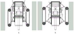
图10所示为实施例2中一种原位黄土抗拉强度测试装置的结构图;Fig. 10 shows the structural diagram of a kind of in-situ loess tensile strength testing device in
图11所示为实施例2中孔内行走机构展开后的结构图;Fig. 11 shows the structural diagram after the traveling mechanism in the hole in
图12所示为实施例2中孔内行走调节盘的俯视图。Figure 12 is a top view of the travel adjustment disc in the hole in
其中,1、刚性仪器外壳;2、电机推进装置;3、轴向应力传感器;4、环形固定盘;5、切削液压泵;6、旋转电机;7、环形切刀;8、贯入杆;9、贯入头;10、压力控制器;11、支撑杆;12、孔内行走液压泵;13、动力齿轮;14、履带;15、液压油管;16、供电线;17、控制操作面板;18、牵引钢丝绳;19、通孔;20、竖向导槽;21、孔内行走调节盘;22、短支杆;23、长支杆;24、行走轮;25、驱动电机;26、驱动齿轮;27、限位块;28、限位槽;29、导向滚珠。Among them, 1. Rigid instrument casing; 2. Motor propulsion device; 3. Axial stress sensor; 4. Annular fixed disk; 5. Cutting hydraulic pump; 6. Rotary motor; 7. Annular cutter; 8. Penetrating rod; 9. Penetration head; 10. Pressure controller; 11. Support rod; 12. Hydraulic pump for traveling in the hole; 13. Power gear; 14. Track; 15. Hydraulic oil pipe; 16. Power supply line; 17. Control operation panel; 18. Traction wire rope; 19. Through hole; 20. Vertical guide groove; 21. Walking adjustment disc in the hole; 22. Short pole; 23. Long pole; 24. Traveling wheel; 25. Driving motor; 26. Driving gear ; 27, limit block; 28, limit groove; 29, guide ball.
具体实施方式Detailed ways
为使本发明实施例的目的、技术方案和优点更加清楚,下面将结合本发明实施例中的附图,对本发明实施例中的技术方案进行清楚、完整地描述,显然,所描述的实施例是本发明一部分实施例,而不是全部的实施例。通常在此处附图中描述和示出的本发明实施例的组件可以以各种不同的配置来布置和设计。In order to make the purpose, technical solutions and advantages of the embodiments of the present invention clearer, the technical solutions in the embodiments of the present invention will be clearly and completely described below in conjunction with the drawings in the embodiments of the present invention. Obviously, the described embodiments It is a part of embodiments of the present invention, but not all embodiments. The components of the embodiments of the invention generally described and illustrated in the figures herein may be arranged and designed in a variety of different configurations.
因此,以下对在附图中提供的本发明的实施例的详细描述并非旨在限制要求保护的本发明的范围,而是仅仅表示本发明的选定实施例。基于本发明中的实施例,本领域普通技术人员在没有作出创造性劳动前提下所获得的所有其他实施例,都属于本发明保护的范围。Accordingly, the following detailed description of the embodiments of the invention provided in the accompanying drawings is not intended to limit the scope of the claimed invention, but merely represents selected embodiments of the invention. Based on the embodiments of the present invention, all other embodiments obtained by persons of ordinary skill in the art without creative efforts fall within the protection scope of the present invention.
实施例1Example 1
如图1所示,本实施例提供的一种原位黄土抗拉强度测试装置包括包括孔内行走机构、孔底切削机构和贯入机构,所述孔内行走机构设置在刚性仪器外壳1的外壁上,可在钻孔中固定及行走,所述孔底切削机构设置于刚性仪器外壳1内部且可沿垂直方向下移实现切削土体动作,所述贯入机构设置在刚性仪器外壳1内部且位于孔底切削机构的上方。As shown in Figure 1, an in-situ loess tensile strength testing device provided in this embodiment includes a traveling mechanism in a hole, a cutting mechanism at the bottom of a hole, and a penetrating mechanism. On the outer wall, it can be fixed and walked in the borehole. The hole bottom cutting mechanism is set inside the
具体的,如图4所示,孔内行走机构包括孔内行走液压泵12、动力齿轮13、支撑杆11和履带14,所述孔内行走液压泵12通过铰接形式连接刚性仪器外壳1与支撑杆11,所述支撑杆11通过锚固形式与动力齿轮13连接,动力齿轮13与履带14为卡槽式啮合。Specifically, as shown in Figure 4, the in-hole traveling mechanism includes an in-hole traveling
所述孔内行走液压泵12通过压力状态的变换控制支撑杆11的收回-张开的动作转换,可控制履带14在25cm-35cm的孔径范围内良好地固定及行走。The moving
如图5所示,孔底切削机构包括切削液压泵5、旋转电机6以及环形切刀7,所述刚性仪器外壳1内部设置有环形固定盘4,所述切削液压泵5的固定端与环形固定盘4的底面连接,所述切削液压泵5的输出端与旋转电机6的固定端连接,所述旋转电机6的驱动端与环形切刀7的上端连接,所述环形切刀7的底部沿其圆周方向设置有切割齿。As shown in Figure 5, the hole bottom cutting mechanism includes a cutting
如图2所示,所述刚性仪器外壳1内壁上沿其圆周方向设置有多条等间距的竖向导槽20,所述旋转电机6的上部设置有与竖向导槽20向配合导条,控制该部分只做竖向直线运动,旋转电机6与刚性仪器外壳1之间有圆形孔隙。所述旋转电机6可采用KT280中空旋转台,其中部预留有通孔19。As shown in Figure 2, the inner wall of the
所述切削液压泵5连接仪器主体与旋转电机6,在孔底切削机构中旋转电机6工作时,切削液压泵5逐步加压,实现环形切刀7的旋转下切动作,下切动作完成后,切削液压泵5压力减至负压状态,切刀缓慢抬升。The cutting
如图6所示,贯入机构包括电机推进装置2、轴向应力传感器3和贯入杆8,电机推进装置2的上端与刚性仪器外壳1内顶壁焊接,所述电机推进装置2的下端与贯入件8的上端焊接,所述轴向应力传感器3焊接在贯入杆8的中部,所述贯入杆8的下端可贯穿旋转电机5上的通孔进入环形切刀7内部,所述贯入杆8的下端则焊接有子弹型的贯入头9。As shown in Figure 6, the penetration mechanism includes a
在本实施例中,所述环形固定盘4的中心处沿其轴向设置有贯通的导向孔,所述导向孔内壁沿其圆周方向设置有多个等间距的导向滚珠29,所述导向滚珠29大约有1/3裸露在导向孔内,且与贯入杆8外壁滚动接触,一方面利用导向滚珠29对贯入杆8进行导向限位,同时由于贯入杆8与导向滚珠29为点面滚动接触,其摩擦阻力极小,不会影响抗拉强度的测试结果。In this embodiment, the center of the annular fixed
轴向应力传感器3与贯入杆8件为一体式设计,可在贯入头9贯入过程中获取轴向最大荷载数据。轴向应力传感器3为压阻式压力传感器,测试精度较高。The
贯入杆8上部与电机推进装置2焊接,电机推进装置2推进及回退速率为1.25mm/min,并可提供20cm的进程。The upper part of the
本实施例还包括牵引钢丝绳18、供电线16、控制操作面板17和压力控制器10。This embodiment also includes a
牵引钢丝绳18承重能力较好,通过焊接或锚固在刚性仪器外壳1上部,方便仪器下放入孔和测试完毕回收。The
供电线16连接控制操作面板17和压力控制器10。The
所述供电线16为变频电缆线,可实现控制操作面板17和压力控制器10之间信号和电能的双重传输。The
压力控制器10通过焊接固定在仪器外表面,接收控制操作面板17的电信号,通过液压油管15外接孔内行走液压泵12和切削液压泵5,可分别控制两部分液压泵的压力状态。The
使用本装置进行原位黄土抗拉强度测试,包括以下步骤:Use this device to test the tensile strength of loess in situ, including the following steps:
步骤1:对黄土待测定区域进行打孔,形成钻孔,测量孔的直径在孔内行走系统部分的伸展范围之内,为25cm-35cm;Step 1: Drill holes in the loess area to be measured to form boreholes. The diameter of the measurement hole is within the extension range of the walking system in the hole, which is 25cm-35cm;
步骤2:如图7(a)所示,孔内行走液压泵12调整为负压状态,支撑杆11带动动力齿轮13使履带14收回,仪器径向缩小,进入钻孔内部;Step 2: As shown in Figure 7(a), the
步骤3:如图7(b)所示,孔内行走液压泵12加压伸长,支撑杆11带动动力齿轮13使履带14挤压孔壁,在牵引钢丝绳1牵引下,动力齿轮13工作带动履14带行走,到孔底后孔内行走液压泵12再次加压仪器固定;Step 3: As shown in Figure 7(b), the
步骤4:如图8(a)、(b)所示,装置到达孔底位置后,旋转电机6开始工作,同时旋转电机6上部连接的2根切削液压泵5状态缓慢加压伸长,控制下部环形切刀7向下旋转切削,在孔底切削得到圆柱形土样;Step 4: As shown in Figure 8 (a) and (b), after the device reaches the bottom of the hole, the
步骤5:切削完成后切削液压泵5调整至负压状态,缓慢提升下部环形切刀7,使切削得到的圆柱形土样处于无侧限状态;Step 5: After the cutting is completed, the cutting
步骤6:如图9(a)、(b)所示,贯入系统电机推进装置2工作,轴向荷载通过贯入杆8加至刚性贯入头9,在轴向压力作用下竖直挤压贯入圆柱形土样;Step 6: As shown in Figure 9(a) and (b), the
步骤7:圆柱形土样受轴向贯入压力发生径向破裂,根据在贯入系统工作过程中轴向应力传感器3记录并传输的数据,如图3所示,该曲线α为土体天然状态下轴向荷载-贯入位移预测曲线,曲线峰值位置对应贯入过程中施加的轴向最大荷载P(N),可按照下列公式计算得到待测土体的抗拉强度σt(kPa)。Step 7: The cylindrical soil sample undergoes radial rupture under the axial penetration pressure. According to the data recorded and transmitted by the

式中,σt—抗拉强度,单位为kPa;In the formula, σ t —tensile strength, unit is kPa;
P—轴向最大荷载,单位为N;P—maximum axial load, unit is N;
K—常数,取决于试样孔径大小和土壤类型,一般取1;K—Constant, depends on sample aperture size and soil type, generally takes 1;
b—试样半径,单位为cm;b—the radius of the sample, in cm;
H—试样高度,单位为cm;H—the height of the sample, in cm;
a—加载贯入头11半径,单位为cm。a—the radius of the
实施例2Example 2
本实施例提供的一种原位黄土抗拉强度测试装置,如图10所示,与实施例1不同的是,在本实施例中的孔内行走机构更小巧、灵活性更高。An in-situ loess tensile strength testing device provided in this embodiment is shown in FIG. 10 . The difference from
所述孔内行走机构包括设置于刚性仪器外壳1上下两端的两组行走组件,所述两组行走组件结构相同,均包括孔内行走调节盘21,所述孔内行走调节盘21套设在刚性仪器外壳1的外壁上,所述孔内行走调节盘21的侧壁上设置有多个等间距的支块,每个支块均铰接有一根短支杆22,所述刚性仪器外壳1的外壁上沿其圆周方向设置有与多个与短支杆22相配合的长支杆23,每个长支杆23的一端与刚性仪器外壳1的外壁铰接,其另一端则设置有行走轮24,所述短支杆22的自由端则与长支杆23的侧壁铰接,所述孔内行走调节盘21上端面的两侧对称设置有两组驱动电机25,所述两组驱动电机25的输出端分别连接有一驱动齿轮26,所述刚性仪器外壳1的外壁上设置有与驱动齿轮26啮合的齿槽(图中未显示),所述驱动电机25通过供电线16与控制操作面板17连接。The walking mechanism in the hole includes two sets of walking assemblies arranged at the upper and lower ends of the
如图12所示,所述孔内行走调节盘21的前后两侧相对称的内壁上分别设置有一限位块27,所述刚性仪器外壳1的前后外壁上设置有与限位块27相配合的限位槽28,所述限位块27可在限位槽28内上下滑动。As shown in Figure 12, a limit block 27 is respectively arranged on the symmetrical inner walls of the front and rear sides of the
使用本装置进行原位黄土抗拉强度测试,包括以下步骤:Use this device to test the tensile strength of loess in situ, including the following steps:
步骤1:对黄土待测定区域进行打孔,形成钻孔,测量孔的直径在孔内行走系统部分的伸展范围之内,为25cm-35cm;Step 1: Drill holes in the loess area to be measured to form boreholes. The diameter of the measurement hole is within the extension range of the walking system in the hole, which is 25cm-35cm;
步骤2:如图10所示,打开驱动电机25,驱动驱动齿轮26啮合齿槽,带动孔内行走调节盘21下移,长支杆23径向缩小,进入钻孔内部;Step 2: As shown in Figure 10, turn on the
步骤3:如图11所示,打开驱动电机25,反向驱动驱动齿轮26拟合齿槽,带动孔内行走调节盘21上移,长支杆23径向扩展,行走轮24挤压孔壁,在牵引钢丝绳1牵引下,行走轮24行走,到孔底后继续反向驱动驱动齿轮26拟合齿槽,带动孔内行走调节盘21上移,行走轮24挤压孔壁增大,刚性仪器外壳1固定;Step 3: As shown in Figure 11, turn on the driving
步骤4:装置到达孔底位置后,旋转电机6开始工作,同时旋转电机6上部连接的2根切削液压泵5状态缓慢加压伸长,控制下部环形切刀7向下旋转切削,在孔底切削得到圆柱形土样;Step 4: After the device reaches the bottom of the hole, the
步骤5:切削完成后切削液压泵5调整至负压状态,缓慢提升下部环形切刀7,使切削得到的圆柱形土样处于无侧限状态;Step 5: After the cutting is completed, the cutting
步骤6:贯入系统电机推进装置2工作,轴向荷载通过贯入杆8加至刚性贯入头9,在轴向压力作用下竖直挤压贯入圆柱形土样;Step 6: The
步骤7:圆柱形土样受轴向贯入压力发生径向破裂,根据模量转换可计算得到待测土体的抗拉强度σt(kPa)。Step 7: The cylindrical soil sample is radially ruptured under the axial penetration pressure, and the tensile strength σ t (kPa) of the soil to be tested can be calculated according to the modulus conversion.
以上所述,仅用以说明本发明的技术方案而非限制,本领域普通技术人员对本发明的技术方案所做的其它修改或者等同替换,只要不脱离本发明技术方案的精神和范围,均应涵盖在本发明的权利要求范围当中。The above is only used to illustrate the technical solution of the present invention and not to limit it. Other modifications or equivalent replacements made by those skilled in the art to the technical solution of the present invention should be considered as long as they do not depart from the spirit and scope of the technical solution of the present invention. fall within the scope of the claims of the present invention.
Claims (5)
Priority Applications (1)
| Application Number | Priority Date | Filing Date | Title |
|---|---|---|---|
| CN202111381048.8A CN114112690B (en) | 2021-11-20 | 2021-11-20 | In-situ loess tensile strength testing device and testing method |
Applications Claiming Priority (1)
| Application Number | Priority Date | Filing Date | Title |
|---|---|---|---|
| CN202111381048.8A CN114112690B (en) | 2021-11-20 | 2021-11-20 | In-situ loess tensile strength testing device and testing method |
Publications (2)
| Publication Number | Publication Date |
|---|---|
| CN114112690A CN114112690A (en) | 2022-03-01 |
| CN114112690B true CN114112690B (en) | 2023-05-26 |
Family
ID=80396872
Family Applications (1)
| Application Number | Title | Priority Date | Filing Date |
|---|---|---|---|
| CN202111381048.8A Expired - Fee Related CN114112690B (en) | 2021-11-20 | 2021-11-20 | In-situ loess tensile strength testing device and testing method |
Country Status (1)
| Country | Link |
|---|---|
| CN (1) | CN114112690B (en) |
Families Citing this family (1)
| Publication number | Priority date | Publication date | Assignee | Title |
|---|---|---|---|---|
| CN119178709B (en) * | 2024-11-26 | 2025-03-11 | 中铁五局集团电务工程有限责任公司 | Gravel penetration stability test device for gravel stratum construction |
Citations (3)
| Publication number | Priority date | Publication date | Assignee | Title |
|---|---|---|---|---|
| CN103806906A (en) * | 2014-01-26 | 2014-05-21 | 北京雷雨达科技有限公司 | Rock mass/soil mass drilling in-situ test device and method |
| CN105738225A (en) * | 2014-12-10 | 2016-07-06 | 北京雷雨达科技有限公司 | Deep-hole rock/soil in-situ test method and robot |
| CN113514347A (en) * | 2021-05-14 | 2021-10-19 | 长安大学 | In-hole in-situ shearing test device and test method |
Family Cites Families (10)
| Publication number | Priority date | Publication date | Assignee | Title |
|---|---|---|---|---|
| US3969929A (en) * | 1975-06-09 | 1976-07-20 | Trw Inc. | Drill module for borehole stress measuring instrument |
| JP5177663B2 (en) * | 2008-09-03 | 2013-04-03 | ケミカルグラウト株式会社 | Uniaxial compressive strength estimation method |
| JP5168696B2 (en) * | 2009-02-19 | 2013-03-21 | 五洋建設株式会社 | Portable cone penetration test equipment |
| CN102607967B (en) * | 2012-04-12 | 2014-04-09 | 中国科学院力学研究所 | Shear measurement device for contractible connecting rod driving type rock-soil aggregate |
| CN204154579U (en) * | 2014-07-29 | 2015-02-11 | 中铁第一勘察设计院集团有限公司 | The proving installation of soil body compression deformation modulus and intensity in a kind of deep hole |
| CN105300756B (en) * | 2015-09-18 | 2017-11-14 | 西安建筑科技大学 | A kind of devices and methods therefor for the sample preparation for directly testing loess tensile strength |
| CN109708985B (en) * | 2019-03-08 | 2024-05-17 | 扬州大学 | Soft rock strength test needle penetration instrument and use method thereof |
| CN110646299B (en) * | 2019-08-28 | 2022-02-25 | 长安大学 | A shearing instrument for in-situ detection of loess holes |
| CN211234524U (en) * | 2019-11-22 | 2020-08-11 | 长安大学 | Loess geological information in-situ detection robot |
| CN113607573B (en) * | 2021-05-14 | 2023-05-05 | 长安大学 | In-situ shearing test device and method for loess in hole |
-
2021
- 2021-11-20 CN CN202111381048.8A patent/CN114112690B/en not_active Expired - Fee Related
Patent Citations (3)
| Publication number | Priority date | Publication date | Assignee | Title |
|---|---|---|---|---|
| CN103806906A (en) * | 2014-01-26 | 2014-05-21 | 北京雷雨达科技有限公司 | Rock mass/soil mass drilling in-situ test device and method |
| CN105738225A (en) * | 2014-12-10 | 2016-07-06 | 北京雷雨达科技有限公司 | Deep-hole rock/soil in-situ test method and robot |
| CN113514347A (en) * | 2021-05-14 | 2021-10-19 | 长安大学 | In-hole in-situ shearing test device and test method |
Also Published As
| Publication number | Publication date |
|---|---|
| CN114112690A (en) | 2022-03-01 |
Similar Documents
| Publication | Publication Date | Title |
|---|---|---|
| Cheng et al. | Non-linear seepage characteristics and influential factors of water injection in gassy seams | |
| CN110185383B (en) | Small-size indoor drilling parameter rapid acquisition device | |
| CN110672411A (en) | Indoor drilling perception test system for rock mass mechanical characteristics | |
| CN113607573B (en) | In-situ shearing test device and method for loess in hole | |
| CN114624126B (en) | Rock-soil in-situ shearing test equipment and method | |
| CN105181199B (en) | A kind of side hole stress relief method of detecting earth stress | |
| CN112412457B (en) | A method for ground pulse topping of hard roof in mining face of open roadway | |
| CN108426789A (en) | Shearing test system and its test method in the hole of deep layer original position | |
| CN113514347B (en) | An in-situ shear test device and test method in a hole | |
| CN102953364A (en) | Multilayer blade-typed multipoint displacement metre anchor head used for soft soil layer | |
| CN105738225B (en) | Deep hole rock/upper home position testing method and test machine people | |
| CN114112690B (en) | In-situ loess tensile strength testing device and testing method | |
| CN107764657A (en) | Simulating two-dimensional loads the experimental rig and method of liquid nitrogen cooling mechanical equivalent of light excavation off-load | |
| CN103115829A (en) | Rock mass drilling and shearing elastic modulus instrument | |
| US3173500A (en) | Sampling device | |
| CN111088972A (en) | Hydraulic fracturing production increasing method and target fracturing construction parameter selection method | |
| CN119666753B (en) | Geological disaster crack measuring device | |
| CN206290254U (en) | Perforation tunnel penetration detection device for oil-gas well | |
| CN204594983U (en) | With the shield structure ground adaptability tester of native cabin simulation | |
| CN115248184A (en) | Method and device for rapidly measuring soil body mechanical parameters in shield construction tunnel | |
| CN206740536U (en) | The lateral dead load of triaxial compressions reverses Rock And Soil test machine people under hole | |
| CN114965095A (en) | Deep-sea in-situ cross plate shear test device and analytical method for the strength of different shear planes of sediments | |
| CN211668948U (en) | Indoor drilling perception test system for rock mass mechanical characteristics | |
| CN205172560U (en) | Oil well layering testing arrangement | |
| CN114934769B (en) | Integrated simulation device for compact gas reservoir fracturing casing pipe-cement sheath and evaluation method thereof |
Legal Events
| Date | Code | Title | Description |
|---|---|---|---|
| PB01 | Publication | ||
| PB01 | Publication | ||
| SE01 | Entry into force of request for substantive examination | ||
| SE01 | Entry into force of request for substantive examination | ||
| GR01 | Patent grant | ||
| GR01 | Patent grant | ||
| CF01 | Termination of patent right due to non-payment of annual fee |
Granted publication date: 20230526 |
|
| CF01 | Termination of patent right due to non-payment of annual fee |