CN114101552B - Guiding device for improving rolling roundness of ring piece - Google Patents
Guiding device for improving rolling roundness of ring piece Download PDFInfo
- Publication number
- CN114101552B CN114101552B CN202111228135.XA CN202111228135A CN114101552B CN 114101552 B CN114101552 B CN 114101552B CN 202111228135 A CN202111228135 A CN 202111228135A CN 114101552 B CN114101552 B CN 114101552B
- Authority
- CN
- China
- Prior art keywords
- circular arc
- arc
- wheel
- guide
- guide wheel
- Prior art date
- Legal status (The legal status is an assumption and is not a legal conclusion. Google has not performed a legal analysis and makes no representation as to the accuracy of the status listed.)
- Active
Links
- 238000005096 rolling process Methods 0.000 title claims abstract description 31
- 238000007789 sealing Methods 0.000 claims abstract description 7
- 238000003754 machining Methods 0.000 claims 1
- 238000000034 method Methods 0.000 abstract description 11
- 239000011248 coating agent Substances 0.000 abstract description 2
- 238000000576 coating method Methods 0.000 abstract description 2
- 239000007769 metal material Substances 0.000 abstract description 2
- 230000008878 coupling Effects 0.000 description 14
- 238000010168 coupling process Methods 0.000 description 14
- 238000005859 coupling reaction Methods 0.000 description 14
- 238000010586 diagram Methods 0.000 description 5
- 238000004519 manufacturing process Methods 0.000 description 4
- 230000008569 process Effects 0.000 description 4
- 238000005516 engineering process Methods 0.000 description 2
- 238000000465 moulding Methods 0.000 description 2
- 238000009987 spinning Methods 0.000 description 2
- 239000002131 composite material Substances 0.000 description 1
- 238000005336 cracking Methods 0.000 description 1
- 238000005520 cutting process Methods 0.000 description 1
- 230000007812 deficiency Effects 0.000 description 1
- 230000007613 environmental effect Effects 0.000 description 1
- 239000000446 fuel Substances 0.000 description 1
- 230000007246 mechanism Effects 0.000 description 1
- 238000012986 modification Methods 0.000 description 1
- 230000004048 modification Effects 0.000 description 1
Images


Classifications
-
- B—PERFORMING OPERATIONS; TRANSPORTING
- B21—MECHANICAL METAL-WORKING WITHOUT ESSENTIALLY REMOVING MATERIAL; PUNCHING METAL
- B21H—MAKING PARTICULAR METAL OBJECTS BY ROLLING, e.g. SCREWS, WHEELS, RINGS, BARRELS, BALLS
- B21H1/00—Making articles shaped as bodies of revolution
- B21H1/06—Making articles shaped as bodies of revolution rings of restricted axial length
-
- Y—GENERAL TAGGING OF NEW TECHNOLOGICAL DEVELOPMENTS; GENERAL TAGGING OF CROSS-SECTIONAL TECHNOLOGIES SPANNING OVER SEVERAL SECTIONS OF THE IPC; TECHNICAL SUBJECTS COVERED BY FORMER USPC CROSS-REFERENCE ART COLLECTIONS [XRACs] AND DIGESTS
- Y02—TECHNOLOGIES OR APPLICATIONS FOR MITIGATION OR ADAPTATION AGAINST CLIMATE CHANGE
- Y02P—CLIMATE CHANGE MITIGATION TECHNOLOGIES IN THE PRODUCTION OR PROCESSING OF GOODS
- Y02P70/00—Climate change mitigation technologies in the production process for final industrial or consumer products
- Y02P70/10—Greenhouse gas [GHG] capture, material saving, heat recovery or other energy efficient measures, e.g. motor control, characterised by manufacturing processes, e.g. for rolling metal or metal working
Landscapes
- Engineering & Computer Science (AREA)
- Mechanical Engineering (AREA)
- Reduction Rolling/Reduction Stand/Operation Of Reduction Machine (AREA)
- Forging (AREA)
Abstract
Description
技术领域technical field
本发明属于金属材料加工技术领域,涉及一种改善环件滚压圆度的导向装置。The invention belongs to the technical field of metal material processing, and relates to a guide device for improving the rolling roundness of ring parts.
背景技术Background technique
随着航空航天、汽车制造、核能工业等众多领域的发展,许多机械零件需要具有应付各种极端环境的能力,这就对零部件的性能提出了更加严峻的要求,同时,以往传统的橡胶密封技术已经不足以满足使用要求,这也就对应用于其中的密封零件提出了更加高的使用条件,密封性能提高百分之一,发动机的推力可以增加百分之一,同时油耗也可相应的降低百分之零点一。为此,要求密封件具有良好的回弹量和形状尺寸。With the development of aerospace, automobile manufacturing, nuclear energy industry and many other fields, many mechanical parts need to have the ability to cope with various extreme environments, which puts forward more stringent requirements on the performance of parts. At the same time, the traditional rubber seal The technology is no longer enough to meet the requirements of use, which also puts forward higher service conditions for the sealing parts used in it. The sealing performance can be increased by one percent, the thrust of the engine can be increased by one percent, and the fuel consumption can also be increased accordingly. Reduced by one-tenth of a percent. For this reason, seals are required to have good springback and shape dimensions.
目前针对封严环的生产工艺主要是滚压成形、旋压成形、液压胀形等方式。其中滚压成形是目前使用最多的工艺,滚压工艺是在旋压工艺中演变过来的,是对坯料同时进行“滚”和“压”的一种复合加工工艺。滚压后的坯料强度大、不易变形、表面质量好、规整度一致、生产效率较高,容易与上下工序组成联动的生产线,所以在航空领域内得到广泛的应用。At present, the production processes for sealing rings are mainly rolling forming, spinning forming, hydraulic bulging and other methods. Among them, rolling forming is the most used process at present. The rolling process is evolved from the spinning process. It is a composite processing process that simultaneously "rolls" and "presses" the blank. The billet after rolling has high strength, is not easy to deform, has good surface quality, uniform regularity, high production efficiency, and is easy to form a production line linked with the upper and lower processes, so it is widely used in the aviation field.
但是在滚压过程中也往往容易出现破裂、失稳、椭圆度高等特点,特别是在大型环件的滚压中,椭圆度是一项极其难以保证的标准,因此,针对这个问题有必要对滚压过程进行改善,使滚压环件的圆度得以保证。However, cracking, instability, and high ellipticity are also prone to occur during the rolling process. Especially in the rolling of large rings, ellipticity is an extremely difficult standard to guarantee. Therefore, it is necessary to address this problem. The rolling process is improved to ensure the roundness of the rolling ring.
发明内容Contents of the invention
本发明的目的是为了解决现有技术中存在对圆度把控的不足之处,提供一种改善环件滚压圆度的导向装置,该装置能够随意拆卸、装夹在不同的机架上对零件滚压进行辅助功能,能够在一定程度上改善成形零件的圆度,提高产品零件的形状尺寸、截面形状规整性。The purpose of the present invention is to solve the deficiency of roundness control in the prior art, and provide a guide device for improving the roundness of ring rolling, which can be disassembled and clamped on different frames at will The auxiliary function of rolling parts can improve the roundness of formed parts to a certain extent, and improve the shape size and cross-sectional shape regularity of product parts.
本发明是通过以下技术方案实现的。The present invention is achieved through the following technical solutions.
本发明所述的一种改善环件滚压圆度的装置,包括圆弧型腔体、外导槽、观察窗口、内导槽、夹紧件、加工区、封闭装置、内导向轮、内联轴杆、外导向轮、外联轴杆。A device for improving the rolling roundness of rings according to the present invention includes an arc-shaped cavity, an outer guide groove, an observation window, an inner guide groove, a clamping piece, a processing area, a closing device, an inner guide wheel, an inner Coupling rod, outer guide wheel, outer coupling shaft rod.
所述圆弧型腔体由两片圆弧形壳体闭合而成,每片圆弧形壳体断面为正梯形或类正梯形(本发明所指的类正梯形为半圆被平行底边的直线切割后的图形,闭合后的圆弧型腔体的内腔形状如图3所述),每片圆弧形壳体相对于闭合面的外侧面,开有两条圆弧形导槽,圆弧形导槽为间断的、相互对应,圆弧形导槽均匀分布于外侧面,并与另一片圆弧形壳体圆弧形导槽的位置相对应;每片圆弧形壳体外边缘中部相对应位置开有观察槽,两片圆弧形壳体的观察槽相合后形成所述的观察窗口;沿两片圆弧形壳体内、外边缘两两对应地均匀焊接有若干封闭装置,用于两片壳体开合,用于坯料的放置和取出。两片圆弧形壳体外侧还分别焊接有夹紧件,闭合后的圆弧型腔体通过夹紧件用螺栓直接固定在机架上,使用时,将夹紧件放置在机架上端,通过螺栓连接起到固定整个装置作用。The arc-shaped cavity is formed by closing two arc-shaped shells, and the cross-section of each arc-shaped shell is a regular trapezoid or a quasi-regular trapezoid (the quasi-regular trapezoid referred to in the present invention is a semicircle with parallel bases. The figure after straight line cutting, the shape of the inner cavity of the closed arc-shaped cavity is shown in Figure 3), and each arc-shaped shell has two arc-shaped guide grooves relative to the outer surface of the closed surface. The arc-shaped guide grooves are intermittent and correspond to each other. The arc-shaped guide grooves are evenly distributed on the outer surface and correspond to the position of the arc-shaped guide grooves of another arc-shaped shell; the outer edge of each arc-shaped shell There is an observation slot at the corresponding position in the middle, and the observation slots of the two arc-shaped shells are combined to form the above-mentioned observation window; along the inner and outer edges of the two arc-shaped shells, a number of closing devices are evenly welded in pairs, It is used for the opening and closing of two pieces of shells, and is used for placing and taking out blanks. The outer sides of the two arc-shaped shells are also welded with clamping parts respectively. The closed arc-shaped cavity is directly fixed on the frame by bolts through the clamping parts. When in use, the clamping parts are placed on the upper end of the frame. The whole device is fixed by bolt connection.
所述两片圆弧形壳体的两条圆弧形导槽分为外导槽和内导槽。The two arc-shaped guide grooves of the two arc-shaped shells are divided into outer guide grooves and inner guide grooves.
所述的外导槽位于圆弧型腔体内腔的外侧,外联轴杆固定在两条外导槽上,外导向轮安装在外联轴杆中间位置。The outer guide grooves are located outside the inner cavity of the arc-shaped cavity, the outer coupling shaft rods are fixed on the two outer guide grooves, and the outer guide wheels are installed in the middle of the outer coupling shaft rods.
所述内导槽位于圆弧型腔体内腔的内侧,内联轴杆固定在两条内导槽上,内导向轮安装在内联轴杆中间位置。The inner guide groove is located inside the inner cavity of the arc-shaped cavity, the inline shaft rod is fixed on the two inner guide grooves, and the inner guide wheel is installed at the middle position of the inner connection shaft rod.
所述的内导向轮与外导向轮在所处位置断面图中处于在同一条垂直线上;所述内导向轮和外导向轮直接与加工件相接触,以保证加工件的整体加工圆度。The inner guide wheel and the outer guide wheel are on the same vertical line in the cross-sectional view of the position; the inner guide wheel and the outer guide wheel are directly in contact with the workpiece to ensure the overall roundness of the workpiece .
所述的外导槽和内导槽的作用是给外联轴杆和内联轴杆提供固定位置。The function of the outer guide groove and the inner guide groove is to provide a fixed position for the outer coupling shaft rod and the inner coupling shaft rod.
所述观察窗口用于观察圆弧型腔体内加工件的成型情况。The observation window is used to observe the molding condition of the workpiece in the arc-shaped cavity.
所述主动轮与从动轮互为凹凸模关系,凹凸模的形状取决于加工件最终成型的形状,主动轮与从动轮分别分布在加工件的加工区的上下两侧且在同一条垂直线上,主动轮与从动轮的间隔距离可根据加工件的形状进行调整。The driving wheel and the driven wheel are in a concave-convex mold relationship, and the shape of the concave-convex mold depends on the final shape of the workpiece. The driving wheel and the driven wheel are respectively distributed on the upper and lower sides of the processing area of the workpiece and on the same vertical line , The distance between the driving wheel and the driven wheel can be adjusted according to the shape of the workpiece.
所述的导向轮的个数按相邻两导向轮圆心与圆弧型腔体圆心连线之间的夹角为30°-60°设置。圆弧型腔体加工件进、出端口的两导向轮圆心与圆弧型腔体圆心连线与圆弧型腔体圆心的垂线的夹角为30°-45。The number of the guide wheels is set according to the angle between the center of two adjacent guide wheels and the line connecting the center of the arc-shaped cavity to 30°-60°. The included angle between the center of the two guide wheels at the inlet and outlet ports of the arc-shaped cavity processing part and the line connecting the center of the arc-shaped cavity and the vertical line of the center of the arc-shaped cavity is 30°-45°.
所述的间断的圆弧形导槽的个数,与导向轮的个数相同。The number of the intermittent arc-shaped guide grooves is the same as the number of the guide wheels.
进一步说,所述的闭合后的圆弧型腔体的夹紧件与机架也可以是通过法兰固定的。Furthermore, the clamping part and the frame of the closed arc-shaped cavity may also be fixed by flanges.
本发明的导向装置的组装过程。The assembly process of the guiding device of the present invention.
(1)打开位于圆弧型腔体两片圆弧形壳体内、外边缘的封闭装置,为放置加工件做准备。(1) Open the closing device located on the inner and outer edges of the two arc-shaped shells of the arc-shaped cavity to prepare for placing the workpiece.
(2)确定内导向轮的个数,将确定好的内导向轮沿圆弧型腔体内部周向方向均匀放置在圆弧型腔体的内。(2) Determine the number of inner guide wheels, and place the determined inner guide wheels evenly in the arc-shaped cavity along the inner circumferential direction of the arc-shaped cavity.
(3)将内联轴杆穿过内导向轮中的滚珠轴承,用螺母与内联轴杆上两侧螺纹连接,将内联轴杆固定在圆弧型腔体上两条平行圆弧形的内导槽中,螺母直接贴紧壳体的表面,保证在滚压过程中不出现松动的情况,并调整内导向轮位置处于内联轴杆中间处。(3) Pass the inline shaft through the ball bearing in the inner guide wheel, use nuts to thread the two sides of the inline shaft, and fix the inline shaft on the arc-shaped cavity with two parallel arcs. In the inner guide groove, the nut is directly attached to the surface of the shell to ensure that there is no looseness during the rolling process, and the position of the inner guide wheel is adjusted to be in the middle of the inner shaft.
(4)将坯料按照内导向轮的轮廓进行放置。(4) Place the blank according to the contour of the inner guide wheel.
(5)采用与内导向轮相同的连接方式,将外导向轮装配至圆弧型腔体内,外联轴杆固定在圆弧型腔体上两条平行圆弧型的外导槽中,外导向轮样式与内导向轮一样,数目一样,并且圆弧型腔体、内导向轮、外导向轮三个部件的圆心应处于同一条水平线上。(5) Using the same connection method as the inner guide wheel, assemble the outer guide wheel into the arc-shaped cavity, and the outer coupling shaft is fixed in two parallel arc-shaped outer guide grooves on the arc-shaped cavity. The guide wheel style is the same as the inner guide wheel, and the number is the same, and the circle centers of the three parts of the arc cavity, the inner guide wheel and the outer guide wheel should be on the same horizontal line.
(6)调整好内导向轮、加工件、外导向轮之间的间隙,内导向轮与加工件之间留出1mm间隙,外导向轮和加工件之间留出1mm间隙。(6) Adjust the gap between the inner guide wheel, the workpiece and the outer guide wheel, leave a gap of 1mm between the inner guide wheel and the workpiece, and leave a gap of 1mm between the outer guide wheel and the workpiece.
(7)将圆弧型腔体关闭,用螺栓将处于圆弧型腔体上下端的封闭装置进行关闭,防止在加工时圆弧型腔体因为震动而打开。(7) Close the arc-shaped cavity, and close the closing device at the upper and lower ends of the arc-shaped cavity with bolts to prevent the arc-shaped cavity from opening due to vibration during processing.
(8)调整好加工区位置,使加工区处于主动轮、从动轮中间。主动轮、从动轮利用机床电机驱动,主动轮和从动轮互为凹凸模关系,凹凸模的形状取决于加工件最终成型的形状。(8) Adjust the position of the processing area so that the processing area is in the middle of the driving wheel and the driven wheel. The driving wheel and the driven wheel are driven by the motor of the machine tool. The driving wheel and the driven wheel are in a concave-convex mold relationship with each other. The shape of the concave-convex mold depends on the final shape of the workpiece.
(9)所述的夹紧件通过螺纹螺母连接或者法兰连接,将整个机构固定在机床的机架上。(9) The clamping parts are connected by threaded nuts or flanges to fix the whole mechanism on the frame of the machine tool.
(10)打开机床,主动轮、从动轮被机床电机带动旋转,两轮的转速相同,旋转方向相反,并且控制两轮的进给量,通过圆弧型腔体上的观察窗口观察加工件成型状况,结合加工件情况不断调整主动轮、从动轮的转速和进给大小。(10) Open the machine tool, the driving wheel and the driven wheel are driven by the machine tool motor to rotate, the speed of the two wheels is the same, the direction of rotation is opposite, and the feed of the two wheels is controlled, and the shape of the workpiece is observed through the observation window on the arc-shaped cavity. According to the situation, the speed and feed size of the driving wheel and the driven wheel are constantly adjusted according to the condition of the workpiece.
(11)加工件加工完成后,控制主动轮、从动轮返回初始位置,关闭机床电机。(11) After the processing of the workpiece is completed, control the driving wheel and driven wheel to return to the initial position, and turn off the machine tool motor.
(12)松开夹紧件上的螺栓,圆弧型腔体从机架上取下,松开圆弧型腔体上下端封闭装置中的螺栓和内联轴杆、外联轴杆两侧的螺母,将内联轴杆、外联轴杆分别从内导槽、外导槽的一侧抽出。(12) Loosen the bolts on the clamping parts, remove the arc-shaped cavity from the frame, loosen the bolts in the upper and lower closing devices of the arc-shaped cavity, and both sides of the inner shaft rod and the outer shaft rod Pull out the inner shaft rod and the outer shaft rod from one side of the inner guide groove and the outer guide groove respectively.
(13)打开圆弧型腔体,将内导向轮和外导向轮取出,最后将成型好的加工件整体拿下。(13) Open the arc-shaped cavity, take out the inner guide wheel and the outer guide wheel, and finally take off the formed workpiece as a whole.
本发明相对于现有技术具有如下的优点。Compared with the prior art, the present invention has the following advantages.
(1)本发明利用一种改善环件滚压圆度的导向装置对滚压零件进行辅助,可以对滚压过程中存在的圆度问题进行较好的控制,同时通过对内导向轮和外导向轮进行镀层处理可以减少导向轮与坯料之间的摩擦,减少对坯料表面的损坏。(1) The present invention uses a guide device to improve the rolling roundness of the ring to assist the rolling parts, which can better control the roundness problem existing in the rolling process, and at the same time, through the inner guide wheel and the outer The coating treatment of the guide wheel can reduce the friction between the guide wheel and the blank, and reduce the damage to the surface of the blank.
(2)本发明适合对一些大型环类零件进行滚压辅助,由于大型环类零件在滚压加工刚开始存在刚度不足的问题,所以本发明可以给大型环类零件提供相应的支撑力,也适合环类零件的多道次滚压成形。(2) The present invention is suitable for rolling assistance to some large-scale ring parts. Since large-scale ring parts have insufficient rigidity at the beginning of the rolling process, the present invention can provide corresponding supporting force for large-scale ring parts, and also It is suitable for multi-pass roll forming of ring parts.
(3)本发明方法简单易行,结构装置简单,并且成形模具可以进行更换,可以实现对不同截面的环类零件进行滚压辅助。(3) The method of the present invention is simple and easy to operate, the structural device is simple, and the forming mold can be replaced, so that rolling assistance for ring parts with different cross-sections can be realized.
附图说明Description of drawings
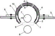
图1为本发明实施例1的一种改善环件滚压圆度的导向装置的装配示意图。Fig. 1 is a schematic diagram of assembly of a guide device for improving the rolling roundness of rings according to
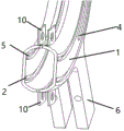
图2为本发明实施例1的夹紧部件的结构放大图。Fig. 2 is an enlarged view of the structure of the clamping part of
图3为本发明实施例1的圆弧型腔体A-A处断面图。Fig. 3 is a cross-sectional view at A-A of the arc-shaped cavity in
图4为图3A位置的放大图。Fig. 4 is an enlarged view of the position in Fig. 3A.
图5为图3B位置的放大图。Fig. 5 is an enlarged view of the position in Fig. 3B.
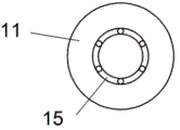
图6为本发明实施例1的内导向轮结构图。Fig. 6 is a structural diagram of the inner guide wheel in
图7为本发明实施例1的封闭装置连接图。Fig. 7 is a connection diagram of the closure device in
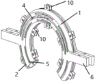
图8为本发明实施例1的圆弧型腔体装置轴测图。Fig. 8 is an isometric view of the arc-shaped cavity device in
图9为本发明实施例1的内腔形状图。Fig. 9 is a shape diagram of the inner cavity of
图10为本发明实施例2夹紧件示意图。Fig. 10 is a schematic diagram of the clamping part of
其中,1-圆弧型腔体,2-外导槽,3-机架,4-观察窗口,5-内导槽,6-夹紧件,7-主动轮,8-从动轮,9-加工区,10-封闭装置,11-内导向轮,12-螺母,13-内联轴杆,14-外导向轮,15-滚珠轴承,16-外联轴杆, 。Among them, 1-arc cavity, 2-outer guide groove, 3-frame, 4-observation window, 5-inner guide groove, 6-clamping parts, 7-driving wheel, 8-driven wheel, 9- Processing area, 10-closed device, 11-inner guide wheel, 12-nut, 13-inner shaft, 14-outer guide wheel, 15-ball bearing, 16-outer shaft, .
具体实施方式Detailed ways
为了达到实现实施例的目的、技术方案和优点更加清楚,下面将结合本发明实施例中的附图,对本发明实施例中的技术方案进行清楚、完整的描述,当然,所描述的实施例是本发明的一部分实施例,并不是全部实施例,基本本发明中的实施例,本领域专业人士或者普通技术人员在没有做出创造性劳动的前提下所获得的所有其他实施例,都隶属于本发明保护的范围。In order to achieve the purpose, technical solutions and advantages of the embodiments more clearly, the technical solutions in the embodiments of the present invention will be clearly and completely described below in conjunction with the accompanying drawings in the embodiments of the present invention. Of course, the described embodiments are Some of the embodiments of the present invention are not all of the embodiments. Basically, the embodiments of the present invention and all other embodiments obtained by professionals in the field or those of ordinary skill without creative work belong to this invention. scope of invention protection.
实施例1。Example 1.
如图1-图9所示,本实施案例提供了一种改善环件滚压圆度的导向装置,该装置固定在机床上实施,包括圆弧型腔体1,外导槽2,观察窗口4,内导槽5,夹紧件6,加工区9,封闭装置10,内导向轮11,内联轴杆13,外导向轮14,外联轴杆16。As shown in Figures 1-9, this implementation case provides a guide device for improving the roundness of ring rolling. The device is fixed on the machine tool and includes an arc-shaped
圆弧型腔体1由两片圆弧形壳体闭合而成,每片圆弧形壳体断面为类正梯形,每片圆弧形壳体相对于闭合面的外侧面,开有两条圆弧形导槽,圆弧形导槽为间断的、相互对应,圆弧形导槽均匀分布于外侧面,并与另一片圆弧形壳体圆弧形导槽的位置相对应;每片圆弧形壳体外边缘中部相对应位置开有观察槽,两片圆弧形壳体的观察槽相合后形成所述的观察窗口4;沿两片圆弧形壳体内、外边缘两两对应地均匀焊接有若干封闭装置10,用于两片壳体开合,用于坯料的放置和取出。两片圆弧形壳体外侧还分别焊接有夹紧件6,闭合后的圆弧型腔体1通过夹紧件6用螺栓直接固定在机架3上,使用时,将夹紧件6放置在机架3上端,通过螺栓连接起到固定整个装置作用。The arc-shaped
两片圆弧形壳体的两条圆弧形导槽分为外导槽2和内导槽5。外导槽2位于圆弧型腔体1内腔的外侧,外联轴杆16固定在两条外导槽2上,外导向轮14安装在外联轴杆16中间位置;内导槽5位于圆弧型腔体1内腔的内侧,内联轴杆13固定在两条内导槽5上,内导向轮11安装在内联轴杆13中间位置。The two arc-shaped guide grooves of the two arc-shaped shells are divided into an
内导向轮11与外导向轮14在所处位置断面图中处于在同一条垂直线上;内导向轮11和外导向轮14直接与加工件相接触,以保证加工件的整体加工圆度。The
主动轮7与从动轮8互为凹凸模关系,本实施例中主动轮7为凸模,从动轮8为凹模;主动轮7与从动轮8分别分布在加工件的加工区9的上下两侧且在同一条垂直线上。The
本实施例中,加工件半径258mm、宽度度18mm、厚度0.3mm的薄壁环形件。In this embodiment, the workpiece is a thin-walled annular piece with a radius of 258 mm, a width of 18 mm, and a thickness of 0.3 mm.
首先确定两内导向轮11圆心与圆弧型腔体1之间连线的夹角为33°,圆弧型腔体1加工件进、出端口的两导向轮圆心与圆弧型腔体1圆心连线与圆弧型腔体1圆心的垂线的夹角为30°。由此,确定内导向轮11为6个,对应的,外导向轮14也为6个。First determine that the angle between the center of the two
然后将圆弧型腔体1上下端封闭装置10的螺栓松开,将圆弧型腔体1完全打开,将内导向轮11按照之前的所设计的角度放置在圆弧型腔体1内部,将内导向轮11通过滚珠轴承15固定在内联轴杆13的中部,内联轴杆13穿过位于圆弧型腔体1上的两条平行圆弧型内导槽5中,将内联轴杆13露出的部分通过螺母12固定在圆弧型腔体1上。Then loosen the bolts of the upper and lower
将相同个数的外导向轮14,按照相同间隔夹角安装至圆弧型腔体1上的两条平行的外导槽2上,圆弧型腔体1、内导向轮11、外导向轮14三个部件的圆心处于同一水平线上,将外导向轮14通过滚珠轴承15固定在外联轴杆16的中部,外联轴杆16穿过位于圆弧型腔体1上的两条平行圆弧型外导槽2,将外联轴杆16露出的部分通过螺母12固定在圆弧型腔体1上。Install the same number of
将加工件放置在圆弧型腔体1中,加工件与内导向轮11和外导向轮14之间留出1mm的间隙。The workpiece is placed in the arc-shaped
将螺杆从位于圆弧型腔体1上下端的封闭装置10的中间的圆形孔洞处穿过,并且用螺母将圆弧型腔体1进行封闭,保证加工件所处区域处于一段封闭环境,排除环境干扰因素。Pass the screw through the circular hole in the middle of the
调整加工区9位置,保证加工区9所处的位置位于主动轮7和从动轮8之间,主动轮7和主动轮8之间距离为9mm。Adjust the position of the
将连接好的整体装置通过夹紧件6与机架3通过螺栓进行配套连接,将整个装置固定在机架上。The connected whole device is matched with the
打开机床电源,机床转机带动主动轮7和从动轮8按照相同大小,方向不同的转速旋转。Turn on the power supply of the machine tool, and the turning of the machine tool drives the
主动轮7一开始的进给速度为1mm/s,待距离加工件0.5mm时,进给速度变为0.1mm/s,并且开始旋转,转速一开始为0.125rad/s,最后达到0.75rad/s,这样的目的是防止加工件因为刚开始加工件刚度不足导致的失稳,通过圆弧型腔体1上的观察窗口4观察加工件成型形状,若加工件出现失稳现象,则应降低主动轮7的进给速度和转速。The feed speed of the
等待加工件加工完成后,控制主动轮7、从动轮8返回初始位置,关闭机床电机。After waiting for the workpiece to be processed, control the
松开夹紧件6上的螺栓,圆弧型腔体1从机架3上取下,松开圆弧型腔体1上封闭装置10中的螺栓和内联轴杆13、外联轴杆16两侧的螺母12,将内联轴杆13、外联轴杆16分别从内导槽5、外导槽2的一侧抽出。Loosen the bolts on the clamping
最后,打开圆弧型腔体1,将内导向轮11和外导向轮14取出,最后将成型好的加工件整体拿下。Finally, the arc-shaped
实施例2。Example 2.
本实施例和实施例1的主要区别是夹紧件6和机架3的装夹方式不同,使用的是法兰连接,如附图10,其余同于实施例1。The main difference between this embodiment and
实施例3。Example 3.
本实施的主要特点是:使用多道次成型的方法,只需要将安装与机床上的主动轮和从动轮进行更换,再按照实施例1相同的操做即可实现。The main feature of this implementation is: using the method of multi-pass molding, it only needs to replace the driving wheel and the driven wheel installed on the machine tool, and then follow the same operation as the first embodiment to realize it.
最后应说明的是:以上所述的实施案例仅仅是本发明的优选实施例,并不代表所有的实施例,并不用于限制本发明,尽管参照前述实施例对本发明进行了详尽的说明,但于本专业领域的技术人员,可以将前面实施例所述的技术方案进行修改,或者对其中部分技术进行等同替换,凡基于本发明原则之内,所做出的任何修改、等同替换、改进等,均包含在本发明保护范围之内。Finally, it should be noted that the above-described implementation cases are only preferred embodiments of the present invention, do not represent all embodiments, and are not intended to limit the present invention. Although the present invention has been described in detail with reference to the foregoing embodiments, Those skilled in the professional field can modify the technical solutions described in the previous embodiments, or perform equivalent replacements for some of the technologies. Any modifications, equivalent replacements, improvements, etc. made based on the principles of the present invention , are included within the protection scope of the present invention.
Claims (2)
Priority Applications (1)
| Application Number | Priority Date | Filing Date | Title |
|---|---|---|---|
| CN202111228135.XA CN114101552B (en) | 2021-10-21 | 2021-10-21 | Guiding device for improving rolling roundness of ring piece |
Applications Claiming Priority (1)
| Application Number | Priority Date | Filing Date | Title |
|---|---|---|---|
| CN202111228135.XA CN114101552B (en) | 2021-10-21 | 2021-10-21 | Guiding device for improving rolling roundness of ring piece |
Publications (2)
| Publication Number | Publication Date |
|---|---|
| CN114101552A CN114101552A (en) | 2022-03-01 |
| CN114101552B true CN114101552B (en) | 2023-05-12 |
Family
ID=80376300
Family Applications (1)
| Application Number | Title | Priority Date | Filing Date |
|---|---|---|---|
| CN202111228135.XA Active CN114101552B (en) | 2021-10-21 | 2021-10-21 | Guiding device for improving rolling roundness of ring piece |
Country Status (1)
| Country | Link |
|---|---|
| CN (1) | CN114101552B (en) |
Citations (11)
| Publication number | Priority date | Publication date | Assignee | Title |
|---|---|---|---|---|
| GB892896A (en) * | 1958-05-20 | 1962-04-04 | James Phineas Zallea | Apparatus for making stress equalizing ring elements for use with self-equalizing expansion joints |
| SU1075556A1 (en) * | 1982-04-27 | 1994-06-30 | Всесоюзный Научно-Исследовательский И Конструкторский Институт По Оборудованию Для Шинной Промышленности | Device for rolling out band material |
| CN103586781A (en) * | 2012-08-13 | 2014-02-19 | 中国石油集团工程技术研究院 | Automatic sand blasting and rust removal device |
| CN203437794U (en) * | 2013-08-30 | 2014-02-19 | 江西制氧机有限公司 | Thin-wall barrel manufacturing, assembling and transferring tool |
| CN103603270A (en) * | 2013-11-20 | 2014-02-26 | 武汉武桥交通装备技术有限公司 | Automatic leveling mechanism for arch bridge inspection cars |
| CN203565565U (en) * | 2013-11-27 | 2014-04-30 | 成都豪能科技股份有限公司 | Hydraulic detection and rectification device for annular parts |
| JP2017087262A (en) * | 2015-11-10 | 2017-05-25 | 日本精工株式会社 | Method of correcting roundness of ring-shaped member |
| CN109296686A (en) * | 2018-09-07 | 2019-02-01 | 熊秀 | A kind of endless metal rubber vibration insulating pad and preparation method thereof |
| CN113084054A (en) * | 2021-03-25 | 2021-07-09 | 武汉理工大学 | Rolling and extruding composite near-net forming method for large-sized outer contour abrupt cross-section ring piece |
| CN213771017U (en) * | 2020-12-08 | 2021-07-23 | 舟山惠生海洋工程有限公司 | Annular hanging row for stand column |
| CN113385532A (en) * | 2021-05-18 | 2021-09-14 | 武汉理工大学 | Self-adaptive control method for stability and roundness in radial and axial rolling process of ultra-large ring |
Family Cites Families (1)
| Publication number | Priority date | Publication date | Assignee | Title |
|---|---|---|---|---|
| CN101966555A (en) * | 2009-07-28 | 2011-02-09 | 上海兴浦旋压车轮有限公司 | Wheel rolling and molding method |
-
2021
- 2021-10-21 CN CN202111228135.XA patent/CN114101552B/en active Active
Patent Citations (11)
| Publication number | Priority date | Publication date | Assignee | Title |
|---|---|---|---|---|
| GB892896A (en) * | 1958-05-20 | 1962-04-04 | James Phineas Zallea | Apparatus for making stress equalizing ring elements for use with self-equalizing expansion joints |
| SU1075556A1 (en) * | 1982-04-27 | 1994-06-30 | Всесоюзный Научно-Исследовательский И Конструкторский Институт По Оборудованию Для Шинной Промышленности | Device for rolling out band material |
| CN103586781A (en) * | 2012-08-13 | 2014-02-19 | 中国石油集团工程技术研究院 | Automatic sand blasting and rust removal device |
| CN203437794U (en) * | 2013-08-30 | 2014-02-19 | 江西制氧机有限公司 | Thin-wall barrel manufacturing, assembling and transferring tool |
| CN103603270A (en) * | 2013-11-20 | 2014-02-26 | 武汉武桥交通装备技术有限公司 | Automatic leveling mechanism for arch bridge inspection cars |
| CN203565565U (en) * | 2013-11-27 | 2014-04-30 | 成都豪能科技股份有限公司 | Hydraulic detection and rectification device for annular parts |
| JP2017087262A (en) * | 2015-11-10 | 2017-05-25 | 日本精工株式会社 | Method of correcting roundness of ring-shaped member |
| CN109296686A (en) * | 2018-09-07 | 2019-02-01 | 熊秀 | A kind of endless metal rubber vibration insulating pad and preparation method thereof |
| CN213771017U (en) * | 2020-12-08 | 2021-07-23 | 舟山惠生海洋工程有限公司 | Annular hanging row for stand column |
| CN113084054A (en) * | 2021-03-25 | 2021-07-09 | 武汉理工大学 | Rolling and extruding composite near-net forming method for large-sized outer contour abrupt cross-section ring piece |
| CN113385532A (en) * | 2021-05-18 | 2021-09-14 | 武汉理工大学 | Self-adaptive control method for stability and roundness in radial and axial rolling process of ultra-large ring |
Also Published As
| Publication number | Publication date |
|---|---|
| CN114101552A (en) | 2022-03-01 |
Similar Documents
| Publication | Publication Date | Title |
|---|---|---|
| CN111346963B (en) | Machining rotary wheel with longitudinal inner ribs for thin-wall cylinder and machining method based on machining rotary wheel | |
| CN112570488B (en) | Spinning-reducing forming method of stepped pipe blank for small and medium-sized bulging forming automobile axle housing | |
| CN114029388A (en) | Reducing-hot spinning forming method of stepped pipe blank for large-size expansion-compression formed automobile axle housing | |
| CN105889744B (en) | A kind of spinning flange ring and its forming technology | |
| CN117086181B (en) | A spinning forming apparatus and method for thin-walled rotating body components | |
| CN114101552B (en) | Guiding device for improving rolling roundness of ring piece | |
| CN109261816B (en) | A kind of plastic joining method and device between metal pipe material and plate | |
| CN101936193B (en) | Method for manufacturing integral nozzle block of large-sized steam turbine | |
| CN113290116A (en) | Opposite-wheel spinning manufacturing process of aluminum skirt special for rocket | |
| CN117140006A (en) | Preprocessing method for bearing bush of low-speed diesel engine | |
| CN207563621U (en) | A kind of Roll-extrusion forming device of cylinder part | |
| CN109622713B (en) | Room-temperature spinning forming method for nickel-based high-temperature alloy composite curved bus member difficult to deform | |
| CN113134539B (en) | A spinning wheel, spinning component and spinning process | |
| CN118616580A (en) | Cone cylinder part and forming method | |
| CN103341514A (en) | Roller extrusion deflashing forming device of curve rotary appearance cylinder part | |
| CN113351721A (en) | Double-roller clamping and expanding spinning and opposite-wheel strong spinning composite forming process for large-size flange | |
| CN117961433A (en) | A forming method for an aluminum/magnesium/aluminum layered composite shell with grid ribs | |
| CN205465356U (en) | Both ends press from both sides tight main shaft | |
| CN106238539A (en) | A kind of device and method in turned-out straight flange hole processed on complex-curved hollow closing part | |
| CN223656865U (en) | A pressure plate for flipping tooling | |
| CN209774330U (en) | Grinding tool for end face of opening sealing ring | |
| CN116748617A (en) | Biaxial differential rotary large-area material reduction electrical machining method | |
| CN111992996B (en) | Method for manufacturing nozzle fairing of 400 MW-grade G/H-grade heavy gas turbine | |
| CN115383142A (en) | Turning method for nonmetal shims | |
| CN206104625U (en) | Device in straight flange hole is made to turning up on hollow closed part of complicated curved surface |
Legal Events
| Date | Code | Title | Description |
|---|---|---|---|
| PB01 | Publication | ||
| PB01 | Publication | ||
| SE01 | Entry into force of request for substantive examination | ||
| SE01 | Entry into force of request for substantive examination | ||
| GR01 | Patent grant | ||
| GR01 | Patent grant |