CN114100907B - Graphite alkene lithium-ion battery pole piece processingequipment - Google Patents
Graphite alkene lithium-ion battery pole piece processingequipment Download PDFInfo
- Publication number
- CN114100907B CN114100907B CN202111413348.XA CN202111413348A CN114100907B CN 114100907 B CN114100907 B CN 114100907B CN 202111413348 A CN202111413348 A CN 202111413348A CN 114100907 B CN114100907 B CN 114100907B
- Authority
- CN
- China
- Prior art keywords
- pole piece
- battery pole
- pipe
- fixedly connected
- fixed connection
- Prior art date
- Legal status (The legal status is an assumption and is not a legal conclusion. Google has not performed a legal analysis and makes no representation as to the accuracy of the status listed.)
- Active
Links
- OKTJSMMVPCPJKN-UHFFFAOYSA-N Carbon Chemical compound [C] OKTJSMMVPCPJKN-UHFFFAOYSA-N 0.000 title claims abstract description 19
- HBBGRARXTFLTSG-UHFFFAOYSA-N Lithium ion Chemical compound [Li+] HBBGRARXTFLTSG-UHFFFAOYSA-N 0.000 title claims description 9
- 229910001416 lithium ion Inorganic materials 0.000 title claims description 9
- 150000001336 alkenes Chemical class 0.000 title claims description 6
- 229910002804 graphite Inorganic materials 0.000 title claims description 6
- 239000010439 graphite Substances 0.000 title claims description 6
- 238000005507 spraying Methods 0.000 claims abstract description 41
- 238000007605 air drying Methods 0.000 claims abstract description 19
- 238000012545 processing Methods 0.000 claims abstract description 17
- WHXSMMKQMYFTQS-UHFFFAOYSA-N Lithium Chemical compound [Li] WHXSMMKQMYFTQS-UHFFFAOYSA-N 0.000 claims abstract description 13
- 229910021389 graphene Inorganic materials 0.000 claims abstract description 13
- 229910052744 lithium Inorganic materials 0.000 claims abstract description 13
- 239000000428 dust Substances 0.000 claims description 41
- 238000000605 extraction Methods 0.000 claims description 18
- 238000003756 stirring Methods 0.000 claims description 17
- 230000007246 mechanism Effects 0.000 claims description 15
- 238000010521 absorption reaction Methods 0.000 claims description 4
- 239000011248 coating agent Substances 0.000 abstract description 60
- 238000000576 coating method Methods 0.000 abstract description 60
- 230000000694 effects Effects 0.000 abstract description 14
- 239000000463 material Substances 0.000 abstract description 11
- 238000000034 method Methods 0.000 abstract description 11
- 230000008569 process Effects 0.000 abstract description 7
- 239000002699 waste material Substances 0.000 abstract description 5
- 238000004804 winding Methods 0.000 abstract description 4
- 238000001035 drying Methods 0.000 abstract description 3
- 239000007921 spray Substances 0.000 description 6
- 238000007790 scraping Methods 0.000 description 5
- 239000007788 liquid Substances 0.000 description 4
- 239000000203 mixture Substances 0.000 description 3
- 230000003749 cleanliness Effects 0.000 description 2
- 230000005484 gravity Effects 0.000 description 2
- 230000036541 health Effects 0.000 description 2
- 239000000843 powder Substances 0.000 description 2
- 230000009286 beneficial effect Effects 0.000 description 1
- 230000008859 change Effects 0.000 description 1
- 238000004891 communication Methods 0.000 description 1
- 230000007547 defect Effects 0.000 description 1
- 238000010586 diagram Methods 0.000 description 1
- 238000007599 discharging Methods 0.000 description 1
- 238000004146 energy storage Methods 0.000 description 1
- 230000002349 favourable effect Effects 0.000 description 1
- 238000007667 floating Methods 0.000 description 1
- 239000012535 impurity Substances 0.000 description 1
- 238000002156 mixing Methods 0.000 description 1
- 238000012986 modification Methods 0.000 description 1
- 230000004048 modification Effects 0.000 description 1
- 238000011160 research Methods 0.000 description 1
- 230000007306 turnover Effects 0.000 description 1
Images


Classifications
-
- B—PERFORMING OPERATIONS; TRANSPORTING
- B05—SPRAYING OR ATOMISING IN GENERAL; APPLYING FLUENT MATERIALS TO SURFACES, IN GENERAL
- B05B—SPRAYING APPARATUS; ATOMISING APPARATUS; NOZZLES
- B05B13/00—Machines or plants for applying liquids or other fluent materials to surfaces of objects or other work by spraying, not covered by groups B05B1/00 - B05B11/00
- B05B13/02—Means for supporting work; Arrangement or mounting of spray heads; Adaptation or arrangement of means for feeding work
- B05B13/0221—Means for supporting work; Arrangement or mounting of spray heads; Adaptation or arrangement of means for feeding work characterised by the means for moving or conveying the objects or other work, e.g. conveyor belts
-
- B—PERFORMING OPERATIONS; TRANSPORTING
- B05—SPRAYING OR ATOMISING IN GENERAL; APPLYING FLUENT MATERIALS TO SURFACES, IN GENERAL
- B05B—SPRAYING APPARATUS; ATOMISING APPARATUS; NOZZLES
- B05B13/00—Machines or plants for applying liquids or other fluent materials to surfaces of objects or other work by spraying, not covered by groups B05B1/00 - B05B11/00
- B05B13/02—Means for supporting work; Arrangement or mounting of spray heads; Adaptation or arrangement of means for feeding work
- B05B13/04—Means for supporting work; Arrangement or mounting of spray heads; Adaptation or arrangement of means for feeding work the spray heads being moved during spraying operation
- B05B13/0405—Means for supporting work; Arrangement or mounting of spray heads; Adaptation or arrangement of means for feeding work the spray heads being moved during spraying operation with reciprocating or oscillating spray heads
- B05B13/041—Means for supporting work; Arrangement or mounting of spray heads; Adaptation or arrangement of means for feeding work the spray heads being moved during spraying operation with reciprocating or oscillating spray heads with spray heads reciprocating along a straight line
-
- B—PERFORMING OPERATIONS; TRANSPORTING
- B05—SPRAYING OR ATOMISING IN GENERAL; APPLYING FLUENT MATERIALS TO SURFACES, IN GENERAL
- B05B—SPRAYING APPARATUS; ATOMISING APPARATUS; NOZZLES
- B05B15/00—Details of spraying plant or spraying apparatus not otherwise provided for; Accessories
-
- B—PERFORMING OPERATIONS; TRANSPORTING
- B05—SPRAYING OR ATOMISING IN GENERAL; APPLYING FLUENT MATERIALS TO SURFACES, IN GENERAL
- B05B—SPRAYING APPARATUS; ATOMISING APPARATUS; NOZZLES
- B05B15/00—Details of spraying plant or spraying apparatus not otherwise provided for; Accessories
- B05B15/20—Arrangements for agitating the material to be sprayed, e.g. for stirring, mixing or homogenising
- B05B15/25—Arrangements for agitating the material to be sprayed, e.g. for stirring, mixing or homogenising using moving elements, e.g. rotating blades
-
- B—PERFORMING OPERATIONS; TRANSPORTING
- B05—SPRAYING OR ATOMISING IN GENERAL; APPLYING FLUENT MATERIALS TO SURFACES, IN GENERAL
- B05B—SPRAYING APPARATUS; ATOMISING APPARATUS; NOZZLES
- B05B16/00—Spray booths
- B05B16/20—Arrangements for spraying in combination with other operations, e.g. drying; Arrangements enabling a combination of spraying operations
-
- B—PERFORMING OPERATIONS; TRANSPORTING
- B05—SPRAYING OR ATOMISING IN GENERAL; APPLYING FLUENT MATERIALS TO SURFACES, IN GENERAL
- B05B—SPRAYING APPARATUS; ATOMISING APPARATUS; NOZZLES
- B05B9/00—Spraying apparatus for discharge of liquids or other fluent material, without essentially mixing with gas or vapour
- B05B9/03—Spraying apparatus for discharge of liquids or other fluent material, without essentially mixing with gas or vapour characterised by means for supplying liquid or other fluent material
- B05B9/04—Spraying apparatus for discharge of liquids or other fluent material, without essentially mixing with gas or vapour characterised by means for supplying liquid or other fluent material with pressurised or compressible container; with pump
- B05B9/0403—Spraying apparatus for discharge of liquids or other fluent material, without essentially mixing with gas or vapour characterised by means for supplying liquid or other fluent material with pressurised or compressible container; with pump with pumps for liquids or other fluent material
-
- B—PERFORMING OPERATIONS; TRANSPORTING
- B05—SPRAYING OR ATOMISING IN GENERAL; APPLYING FLUENT MATERIALS TO SURFACES, IN GENERAL
- B05D—PROCESSES FOR APPLYING FLUENT MATERIALS TO SURFACES, IN GENERAL
- B05D3/00—Pretreatment of surfaces to which liquids or other fluent materials are to be applied; After-treatment of applied coatings, e.g. intermediate treating of an applied coating preparatory to subsequent applications of liquids or other fluent materials
- B05D3/04—Pretreatment of surfaces to which liquids or other fluent materials are to be applied; After-treatment of applied coatings, e.g. intermediate treating of an applied coating preparatory to subsequent applications of liquids or other fluent materials by exposure to gases
- B05D3/0406—Pretreatment of surfaces to which liquids or other fluent materials are to be applied; After-treatment of applied coatings, e.g. intermediate treating of an applied coating preparatory to subsequent applications of liquids or other fluent materials by exposure to gases the gas being air
-
- B—PERFORMING OPERATIONS; TRANSPORTING
- B08—CLEANING
- B08B—CLEANING IN GENERAL; PREVENTION OF FOULING IN GENERAL
- B08B1/00—Cleaning by methods involving the use of tools
- B08B1/10—Cleaning by methods involving the use of tools characterised by the type of cleaning tool
- B08B1/12—Brushes
-
- B—PERFORMING OPERATIONS; TRANSPORTING
- B08—CLEANING
- B08B—CLEANING IN GENERAL; PREVENTION OF FOULING IN GENERAL
- B08B1/00—Cleaning by methods involving the use of tools
- B08B1/20—Cleaning of moving articles, e.g. of moving webs or of objects on a conveyor
-
- B—PERFORMING OPERATIONS; TRANSPORTING
- B08—CLEANING
- B08B—CLEANING IN GENERAL; PREVENTION OF FOULING IN GENERAL
- B08B5/00—Cleaning by methods involving the use of air flow or gas flow
- B08B5/04—Cleaning by suction, with or without auxiliary action
- B08B5/043—Cleaning travelling work
-
- H—ELECTRICITY
- H01—ELECTRIC ELEMENTS
- H01M—PROCESSES OR MEANS, e.g. BATTERIES, FOR THE DIRECT CONVERSION OF CHEMICAL ENERGY INTO ELECTRICAL ENERGY
- H01M4/00—Electrodes
- H01M4/02—Electrodes composed of, or comprising, active material
- H01M4/04—Processes of manufacture in general
- H01M4/0402—Methods of deposition of the material
- H01M4/0404—Methods of deposition of the material by coating on electrode collectors
-
- H—ELECTRICITY
- H01—ELECTRIC ELEMENTS
- H01M—PROCESSES OR MEANS, e.g. BATTERIES, FOR THE DIRECT CONVERSION OF CHEMICAL ENERGY INTO ELECTRICAL ENERGY
- H01M4/00—Electrodes
- H01M4/02—Electrodes composed of, or comprising, active material
- H01M4/13—Electrodes for accumulators with non-aqueous electrolyte, e.g. for lithium-accumulators; Processes of manufacture thereof
- H01M4/139—Processes of manufacture
-
- Y—GENERAL TAGGING OF NEW TECHNOLOGICAL DEVELOPMENTS; GENERAL TAGGING OF CROSS-SECTIONAL TECHNOLOGIES SPANNING OVER SEVERAL SECTIONS OF THE IPC; TECHNICAL SUBJECTS COVERED BY FORMER USPC CROSS-REFERENCE ART COLLECTIONS [XRACs] AND DIGESTS
- Y02—TECHNOLOGIES OR APPLICATIONS FOR MITIGATION OR ADAPTATION AGAINST CLIMATE CHANGE
- Y02E—REDUCTION OF GREENHOUSE GAS [GHG] EMISSIONS, RELATED TO ENERGY GENERATION, TRANSMISSION OR DISTRIBUTION
- Y02E60/00—Enabling technologies; Technologies with a potential or indirect contribution to GHG emissions mitigation
- Y02E60/10—Energy storage using batteries
Landscapes
- Engineering & Computer Science (AREA)
- Chemical & Material Sciences (AREA)
- Manufacturing & Machinery (AREA)
- Chemical Kinetics & Catalysis (AREA)
- Electrochemistry (AREA)
- General Chemical & Material Sciences (AREA)
- Materials Engineering (AREA)
- Battery Electrode And Active Subsutance (AREA)
Abstract
The invention discloses a graphene lithium battery pole piece processing device, and particularly relates to the technical field of battery pole piece processing. The device can ensure that two surfaces of the battery pole piece are positioned above the battery pole piece by winding and steering the battery pole piece by the supporting roller, so that the problem of waste caused by falling of the coating is avoided, the aim of fully utilizing the coating is fulfilled, the cost is saved, the device can move left and right in a reciprocating manner in the material spraying process, good material spraying and air drying effects are achieved, the uniformity of material spraying and drying is guaranteed, the coating efficiency is improved, the double-surface coating effect of the battery pole piece is more obvious, and the device has better popularization value.
Description
Technical Field
The invention relates to the technical field of battery pole piece processing, in particular to a graphene lithium battery pole piece processing device.
Background
In recent years, with the continuous and deep research of lithium ion batteries, the lithium ion battery power supply has become more and more widely used in daily life, and the occupancy of the lithium ion battery power supply in the fields of vehicles, electric equipment, energy storage base stations and the like is increasing day by day.
In the in-process of processing graphite alkene lithium-ion battery pole piece, often need use coating device to carry out the coating processing to the pole piece, the mode that generally adopts the single face coating among the prior art coats the pole piece, but when carrying out the coating of second face, on the basis of accomplishing first face thick liquids coating, hardly guarantee the thick liquids coating effect of second face and reach the requirement, and coating efficiency is lower, it is consuming time longer, and if directly carry out two-sided coating, the one side that is located the below is at the in-process of coating, the coating of paining falls under the effect of gravity easily, not only can cause the waste of coating, and can make the effect of coating relatively poor, therefore, need improve graphite alkene lithium-ion battery pole piece processingequipment among the prior art.
Disclosure of Invention
In order to overcome the defects in the prior art, the invention provides a graphene lithium battery pole piece processing device, and the technical problems to be solved by the invention are that: generally adopt the mode of single face coating to scribble the utmost point piece among the prior art, but when carrying out the second face coating, on the basis of accomplishing first face thick liquids coating, it reaches the requirement to hardly guarantee the thick liquids coating effect of second face to coating efficiency is lower, and is consuming time longer, and if directly carry out two-sided coating, the one side that is located the below is at the in-process of coating, and the coating of paining falls under the effect of gravity easily, not only can cause the waste of coating, can make the relatively poor problem of effect of coating moreover.
In order to achieve the purpose, the invention provides the following technical scheme: the utility model provides a graphite alkene lithium-ion battery pole piece processingequipment, includes the bottom plate, the front of bottom plate and the back fixed connection of two roller set, the front of bottom plate and the back fixed connection of backing roll, the surface of backing roll and two roller set is provided with same battery pole piece, the backing roll ensures that the battery pole piece is two-sided up, the front of bottom plate and the back fixed connection of box, the front of box and the back fixed connection of fixed plate, the right flank of fixed plate and the left surface fixed connection of extraction pump, the feed inlet of extraction pump is linked together with the one end of inlet pipe, the other end of inlet pipe passes the front of fixed plate and box inner wall and is located the back of box inner wall, the discharge gate of extraction pump is linked together with the one end of spraying pipe.
The other two ends of the spraying pipe are respectively communicated with the front of an elastic mechanism, the other two ends of the spraying pipe are respectively connected with the front of the elastic mechanism in an overlapped mode, a rotating shaft is connected in the cam in a clamped mode, the front of the rotating shaft is fixedly connected with an output shaft of an extraction pump, the other two ends of the rotating shaft are fixedly connected with the back of the elastic mechanism and the front of the bottom plate, the front of the bottom plate is fixedly connected with the back of the shell, the front of the inner wall of the shell is fixedly connected with the front of a dust collector, a dust inlet of the dust collector is communicated with one end of a connecting pipe, the connecting pipe is connected to the left side face and the back of the shell in a clamped mode, the other two ends of the connecting pipe are respectively communicated with one end of a conveying pipe, and the other two ends of the conveying pipe are respectively communicated with one end of a communicating pipe.
The other both ends of communicating pipe are linked together, every with the right-hand member of a dust absorption head group respectively two supporting seats of the outer fixed surface of dust absorption head group are connected with, the back of supporting seat and the positive fixed connection of bottom plate, the top two the equal fixedly connected with brush of opposite face of two supporting seats on supporting seat and the below right side, two the back of brush and the positive overlap joint of battery pole piece, all the other four two scraper blades of supporting seat fixedly connected with, two the back of scraper blade and the positive overlap joint of battery pole piece.
As a further scheme of the invention: the part of the spraying pipe is arranged as an elastic hose.
As a further scheme of the invention: elastic mechanism includes two connecting plates, two the opposite face of connecting plate respectively with the first group of spraying and air-dry both ends fixed connection about the first group, the front of the first group of spraying is linked together with the other one end of spray tube, the left side the left surface of connecting plate respectively with the right-hand member fixed connection of movable rod and first spring, first spring cup joints the surface at the movable rod, the left end of movable rod and the surperficial overlap joint of cam, the surface of movable rod has cup jointed the movable sleeve, the movable sleeve joint is at the right flank of box, the right flank of movable sleeve and the left end fixed connection of first spring.
As a further scheme of the invention: elastic mechanism includes two connecting plates, two the opposite face of connecting plate is organized and air-dries both ends fixed connection about the head group with the spraying respectively, the front of spraying head group is linked together with the other one end of spraying pipe, the left side the left surface of connecting plate respectively with the right-hand member fixed connection of movable rod and first spring, first spring cup joints the surface at the movable rod, the left end of movable rod and the overlap joint of surface of cam, the movable sleeve has been cup jointed to the surface of movable rod, the movable sleeve joint is at the right flank of box, the right flank of movable sleeve and the left end fixed connection of first spring.
As a further scheme of the invention: the outer surface of the shell is fixedly connected with the right side face of the fan, an air outlet of the fan is communicated with one end of the air pipe, and the other two ends of the air pipe are respectively communicated with the front face of one air drying head group.
As a further scheme of the invention: the air pipe is partially arranged into an elastic hose.
As a further scheme of the invention: the right flank and the equal swing joint of lower surface of casing have the apron, the surperficial joint of apron has the filter screen.
As a further scheme of the invention: the outer fixed surface of pivot is connected with a plurality of stirring leaf, the surface of pivot has cup jointed two bearings, two the bearing joint is at the front and the back of box inner wall respectively.
As a further scheme of the invention: the back of the shell is provided with an observation window.
As a further scheme of the invention: the left side of the box body is communicated with the right end of the feeding head, and the left side of the box body is communicated with the right end of the discharge valve.
The invention has the beneficial effects that:
1. the winding and steering device can ensure that two surfaces of the battery pole piece are positioned above the battery pole piece by winding and steering the supporting roller, so that the problem of waste caused by falling of the coating is avoided, the aim of fully utilizing the coating is fulfilled, the cost is saved, the device can move left and right in a reciprocating manner in the process of spraying the material, good spraying and air drying effects are achieved, the uniformity of spraying and drying is guaranteed, the coating efficiency is improved, the double-surface coating effect of the battery pole piece is more obvious, and the winding and steering device has better popularization value;
2. according to the invention, the surface of the battery pole piece can be cleaned in the conveying process of the battery pole piece through the brush, so that the cleanliness of the surface of the battery pole piece is ensured, the coating effect of the battery pole piece is more facilitated, the dust collector can effectively absorb falling dust through the dust collection head group through the suction force of the dust collector, the dust is prevented from floating in the air, the body health of workers can be ensured, meanwhile, a good working environment can be ensured, the scraper can scrape the coated battery pole piece through the scraper, so that the coating on the surface of the battery pole piece can be kept uniform, and the coating quality of the battery pole piece is improved;
3. according to the invention, the extracting pump drives the rotating shaft to rotate, so that the stirring blades can be driven to rotate, the stirring blades can stir and mix the coating, the coating is prevented from being layered in the material conveying process, the quality of the coating can be further ensured, a better coating effect can be brought to follow-up, the extracting pump can be used for carrying out self functional material conveying and spraying, the stirring blades and the cam can be driven to rotate, the purposes of mixing, left-right reciprocating uniform air drying and material spraying can be further achieved, the investment of power equipment is reduced, the energy is saved, the environment is protected, and the problem of saving the investment cost is also achieved.
Drawings
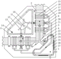
FIG. 1 is a schematic cross-sectional view of the front view of the present invention;
FIG. 2 is a front view of the present invention;
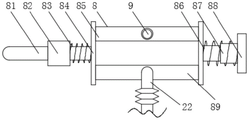
FIG. 3 is a schematic cross-sectional view of the elastic mechanism of the present invention;
FIG. 4 is a schematic diagram of a right-view partial cross-sectional structure of the present invention;
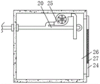
FIG. 5 is a sectional view of the housing of the present invention;
FIG. 6 is a schematic sectional view of the bottom of the container body according to the present invention;
in the figure: 1 bottom plate, 2 roller sets, 3 supporting rollers, 4 battery pole pieces, 5 boxes, 6 fixing plates, 7 extraction pumps, 8 elastic mechanisms, 81 movable rods, 82 movable sleeves, 83 first springs, 84 connecting plates, 85 spraying head sets, 86 telescopic rods, 87 second springs, 88 supporting plates, 89 air drying head sets, 9 spraying pipes, 10 cams, 11 rotating shafts, 12 stirring blades, 13 observation windows, 14 feeding pipes, 15 dust collection head sets, 16 brushes, 17 supporting seats, 18 communicating pipes, 19 conveying pipes, 20 connecting pipes, 21 scraping plates, 22 air pipes, 23 fans, 24 cover plates, 25 dust collectors, 26 shells, 27 filter screens, 28 discharge valves, 29 feeding heads and 30 bearings.
Detailed Description
The technical solutions in the embodiments of the present invention will be clearly and completely described below with reference to the drawings in the embodiments of the present invention, and it is obvious that the described embodiments are only a part of the embodiments of the present invention, and not all of the embodiments. All other embodiments, which can be derived by a person skilled in the art from the embodiments given herein without making any creative effort, shall fall within the protection scope of the present invention.
As shown in FIGS. 1-6, the invention provides a graphene lithium battery pole piece processing device, which comprises a bottom plate 1, wherein the front surface of the bottom plate 1 is fixedly connected with the back surfaces of two roller sets 2, the roller sets 2 are arranged to support a battery pole piece 4, the friction force of the battery pole piece 4 can be reduced, the smooth sliding of the battery pole piece 4 is ensured, meanwhile, the roller sets 2 can extrude the battery pole piece 4 and a coating, the firmness of the combination of the battery pole piece 4 and the coating is ensured, the front surface of the bottom plate 1 is fixedly connected with the back surfaces of supporting rollers 3, the supporting rollers 3 are obliquely arranged to effectively turn over the battery pole piece 4, so that the two surfaces of the battery pole piece 4 can be ensured to face upwards, the problem of waste caused by the falling of the coating is avoided, the same battery pole piece 4 is arranged on the outer surfaces of the supporting rollers 3 and the two roller sets 2, backing roll 3 ensures battery sheet 4 two-sided up, the front of bottom plate 1 and the back fixed connection of box 5, the front of box 5 and the back fixed connection of fixed plate 6, the right flank of fixed plate 6 and the left flank fixed connection of extraction pump 7, through setting up extraction pump 7, extraction pump 7 not only can carry out the functional defeated material of self and spout the material, can also drive stirring leaf 12 and cam 10 rotation, and then can reach simultaneously mix and control reciprocal even air-dry and spout the purpose of material, power equipment's input has been reduced, not only energy-concerving and environment-protective, and the problem of input cost is saved has been reached, the feed inlet of extraction pump 7 is linked together with the one end of inlet pipe 14, the other end of inlet pipe 14 passes the front of fixed plate 6 and box 5 inner wall and is located the back of box 5 inner wall, the discharge gate of extraction pump 7 is linked together with the one end of spraying pipe 9.
The other two ends of the spraying pipe 9 are respectively communicated with the front surface of one elastic mechanism 8, the surfaces of the two elastic mechanisms 8 are lapped with the surface of a cam 10, a rotating shaft 11 is clamped in the cam 10, the front surface of the rotating shaft 11 is fixedly connected with an output shaft of an extraction pump 7, the back surfaces of the two elastic mechanisms 8 are fixedly connected with the front surface of the bottom plate 1, the front surface of the bottom plate 1 is fixedly connected with the back surface of a shell 26, the front surface of the inner wall of the shell 26 is fixedly connected with the front surface of a dust collector 25, a dust inlet of the dust collector 25 is communicated with one end of a connecting pipe 20, the connecting pipe 20 is clamped on the left side surface and the back surface of the shell 26, the other two ends of the connecting pipe 20 are respectively communicated with one end of a conveying pipe 19, and the dust collector 25, a dust collection head group 15, a communicating pipe 18, the conveying pipe 19 and the connecting pipe 20 are arranged, so that the dust collector 25 can effectively absorb falling dust through the dust collection head group 15, and are sequentially input into the communicating pipe 18, the conveying pipe 19 and the connecting pipe 20, and finally discharged into the shell 26 and collected, so that dust can be prevented from flying in the air, the body health of workers can be guaranteed, a good working environment can be guaranteed, and the other two ends of the conveying pipe 19 are respectively communicated with one end of one communicating pipe 18.
The other two ends of the communicating pipe 18 are respectively communicated with the right end of one dust collection head group 15, the outer surface of each dust collection head group 15 is fixedly connected with two supporting seats 17, the back surfaces of the supporting seats 17 are fixedly connected with the front surface of the bottom plate 1, the opposite surfaces of the two supporting seats 17 at the top and the two supporting seats 17 at the bottom right side are fixedly connected with the hairbrush 16, through the hairbrush 16, the hairbrush 16 can clean the surface of the battery pole piece 4 in the conveying process, the cleanliness of the surface of the battery pole piece 4 is ensured, so that the coating effect of the battery pole piece 4 is more favorable, the back surfaces of the two hairbrushes 16 are in lap joint with the front surface of the battery pole piece 4, the other four supporting seats 17 are fixedly connected with two scraping plates 21, through the arrangement of the scraping plates 21, the scraping plates 21 can scrape the coated battery pole piece 4, and the coating on the surface of the battery pole piece 4 can keep uniformity, the coating quality of the battery pole piece 4 is improved, and the back surfaces of the two scraping plates 21 are in lap joint with the front surface of the battery pole piece 4.
As shown in fig. 1, the part of the spraying pipe 9 is an elastic hose, and the spraying pipe 9 is arranged, and the part of the spraying pipe 9 is the elastic hose, so that the part of the spraying pipe 9 can be moved, and the moving work of the spraying head group 85 can be ensured.
As shown in fig. 2 and 3, the elastic mechanism 8 includes two connecting plates 84, opposite surfaces of the two connecting plates 84 are respectively fixedly connected with left and right ends of the spray head group 85 and the air drying head group 89, a front surface of the spray head group 85 is communicated with the other end of the spray tube 9, a left side surface of the left connecting plate 84 is respectively fixedly connected with right ends of the movable rod 81 and the first spring 83, the cam 10, the first spring 83 and the second spring 87 are arranged so that the cam 10 can extrude the spray head group 85 to move through the movable rod 81, and elastic forces of the first spring 83 and the second spring 87 can push the spray head group 85 to move oppositely, so that the cam 10 is matched with the first spring 83 and the second spring 87 to achieve the operation of reciprocating left and right for spraying and air drying, thereby ensuring uniformity of air drying, the first spring 83 is sleeved on an outer surface of the movable rod 81, a left end of the movable rod 81 is overlapped with a surface of the cam 10, the outer surface of the movable rod 81 is sleeved with a movable sleeve 82, the movable sleeve 82 is arranged, so that smooth sliding operation of the movable rod 81 can be guaranteed, the movable sleeve 82 is clamped on the right side surface of the box body 5, the right side surface of the movable sleeve 82 is fixedly connected with the left end of a first spring 83, the front surface of the bottom plate 1 is fixedly connected with the back surface of a supporting plate 88, the left side surface of the supporting plate 88 is fixedly connected with a second spring 87 and the right end of an expansion rod 86, the expansion stability of the second spring 87 can be guaranteed by arranging the expansion rod 86, the moving stability of the spraying head group 85 and the air drying head group 89 can be further guaranteed, the second spring 87 is sleeved on the outer surface of the expansion rod 86, the left ends of the second spring 87 and the expansion rod 86 are fixedly connected with the right side surface of a right side connecting plate 84, the outer surface of the shell 26 is fixedly connected with the right side surface of the fan 23, by arranging the fan 23 and the air drying head group 89, make fan 23 can dry the operation through air-drying head group 89, thereby can accelerate the drying rate of coating, the air outlet of fan 23 is linked together with the one end of tuber pipe 22, the other both ends of tuber pipe 22 are linked together with the front of an air-drying head group 89 respectively, the part of tuber pipe 22 sets up to elastic hose, set up to elastic hose through the part with tuber pipe 22, and elastic hose has the elasticity, and then can ensure the work of air-drying head group 89 normal removal.
As shown in fig. 6, the cover plate 24 is movably connected to the right side surface and the lower surface of the casing 26, the cover plate 24 is arranged, so that the cover plate 24 can be conveniently opened to clean impurities inside the casing 26, the filter screen 27 is clamped on the surface of the cover plate 24, the filter screen 27 is arranged to ensure the air inside the casing 26 to be discharged, and then the normal dust discharging work can be achieved, and meanwhile, dust can be intercepted, and the dust is prevented from leaking out, the outer surface of the rotating shaft 11 is fixedly connected with a plurality of stirring blades 12, the rotating shaft 11 is driven to rotate by the extracting pump 7 through the arrangement of the rotating shaft 11 and the stirring blades 12, and then the stirring blades 12 can be driven to rotate, so that the stirring blades 12 can stir and mix the coating, the coating is prevented from being layered in the material conveying process, and the quality of the coating can be ensured, and a better coating effect can be brought for the following, two bearings 30 have been cup jointed to the surface of pivot 11, through setting up bearing 30, make pivot 11 can carry out steady rotation in bearing 30, thereby can ensure the work of the steady pivoted of stirring leaf 12, two bearings 30 joint respectively are at the front and the back of 5 inner walls of box, casing 26's the back is provided with observation window 13, through setting up observation window 13, thereby be convenient for look over the surplus of the inside coating of box 5, so that the work of in time adding, the left surface of box 5 is linked together with the right-hand member of feed head 29, through setting up feed head 29, and then conveniently pour into coating into box 5 in, the left surface of box 5 is linked together with the right-hand member of discharge valve 28, through setting up discharge valve 28, and then conveniently discharge coating, with this work that can change.
The working principle of the invention is as follows:
s1, when the battery pole piece conveying device needs to be used, coating is injected into the box body 5 through the feeding head 29, then the dust collector 25 is controlled to work, and because the battery pole piece 4 is in the conveying process, the two brushes 16 can clean the two sides of the battery pole piece 4, so that the dust collector 25 can absorb falling dust through the dust collecting head group 15, the dust enters the communicating pipe 18, then enters the conveying pipe 19 through the communicating pipe 18, enters the connecting pipe 20 through the conveying pipe 19, and then is discharged into the shell 26 through the dust outlet of the dust collector 25 to be collected;
s2, controlling the extraction pump 7 to work, enabling the extraction pump 7 to drive the rotating shaft 11 to rotate, enabling the rotating shaft 11 to drive the stirring blades 12 to rotate, enabling the stirring blades 12 to mix and stir the coating, enabling the extraction pump 7 to extract the coating through the feeding pipe 14, enabling the coating to be input into the spraying pipe 9, enabling the coating to enter the two spraying head groups 85 through the spraying pipe 9, enabling the two spraying head groups 85 to coat the two sides of the battery pole piece 4, simultaneously controlling the fan 23 to work, further enabling the fan 23 to blow out the air through the air drying head group 89 through the air pipe 22 for air drying operation, and during coating, the rotating shaft 11 drives the cam 10 to rotate, enabling the cam 10 to extrude the two movable rods 81, enabling the movable rods 81 to push the spraying head group 85 and the air drying head group 89 to move, and enabling the first spring 83 and the second spring 87 to deform;
s3, if the convex surface of the cam 10 is far away from the movable rod 81, the elastic force of the first spring 83 and the second spring 87 can drive the air drying head group 89 and the spraying head group 85 to move reversely, so that the cam 10 can drive the air drying head group 89 and the spraying head group 85 to move left and right in a reciprocating manner to coat and dry the coating, and can also uniformly scrape the coating through the scraper 21, so that the coating is more uniform, meanwhile, the scraped powder can be sucked through the dust collection head group 15, and enters the conveying pipe 19 and the connecting pipe 20 through the communicating pipe 18, and finally, the powder is discharged into the shell 26 through the dust outlet of the dust collector 25 to be collected.
The points to be finally explained are: first, in the description of the present application, it should be noted that, unless otherwise specified and limited, the terms "mounted," "connected," and "connected" should be understood broadly, and may be a mechanical connection or an electrical connection, or a communication between two elements, and may be a direct connection, and "upper," "lower," "left," and "right" are only used to indicate a relative positional relationship, and when the absolute position of the object to be described is changed, the relative positional relationship may be changed;
secondly, the method comprises the following steps: in the drawings of the disclosed embodiments of the invention, only the structures related to the disclosed embodiments are referred to, other structures can refer to common designs, and the same embodiment and different embodiments of the invention can be combined with each other without conflict;
and finally: the above description is only for the purpose of illustrating the preferred embodiments of the present invention and is not to be construed as limiting the invention, and any modifications, equivalents, improvements and the like that are within the spirit and principle of the present invention are intended to be included in the scope of the present invention.
Claims (10)
1. The utility model provides a graphite alkene lithium-ion battery pole piece processingequipment, includes bottom plate (1), its characterized in that: the front of bottom plate (1) and the back fixed connection of two roller set (2), the front of bottom plate (1) and the back fixed connection of backing roll (3), the surface of backing roll (3) and two roller set (2) is provided with same battery pole piece (4), backing roll (3) guarantee battery pole piece (4) two sides up, the front of bottom plate (1) and the back fixed connection of box (5), the front of box (5) and the back fixed connection of fixed plate (6), the right flank of fixed plate (6) and the left flank fixed connection of extraction pump (7), the feed inlet of extraction pump (7) is linked together with the one end of inlet pipe (14), the other end of inlet pipe (14) passes the front of fixed plate (6) and box (5) inner wall and is located the back of box (5) inner wall, a discharge hole of the extraction pump (7) is communicated with one end of the spraying pipe (9);
the other two ends of the spraying pipe (9) are respectively communicated with the front of one elastic mechanism (8), the surfaces of the two elastic mechanisms (8) are overlapped with the surface of the cam (10), a rotating shaft (11) is connected in the cam (10) in a clamping manner, the front of the rotating shaft (11) is fixedly connected with an output shaft of the extraction pump (7), the back surfaces of the two elastic mechanisms (8) are fixedly connected with the front surface of the bottom plate (1), the front surface of the bottom plate (1) is fixedly connected with the back surface of the shell (26), the front surface of the inner wall of the shell (26) is fixedly connected with the front surface of the dust collector (25), a dust inlet of the dust collector (25) is communicated with one end of a connecting pipe (20), the connecting pipe (20) is connected with the left side surface and the back surface of the shell (26) in a clamping manner, the other two ends of the connecting pipe (20) are respectively communicated with one end of a conveying pipe (19), the other two ends of the conveying pipe (19) are respectively communicated with one end of a communicating pipe (18);
the other both ends of communicating pipe (18) are linked together, every with the right-hand member of a dust absorption head group (15) respectively the outer fixed surface of dust absorption head group (15) is connected with two supporting seats (17), the back of supporting seat (17) and the front fixed connection of bottom plate (1), the top two equal fixedly connected with brush (16), two of the opposite face of two supporting seats (17) on supporting seat (17) and the below right side the back of brush (16) and the positive overlap joint of battery pole piece (4), all the other four two scraper blades (21), two of supporting seat (17) fixedly connected with the back of scraper blade (21) and the positive overlap joint of battery pole piece (4).
2. The graphene lithium battery pole piece processing device of claim 1, characterized in that: the part of the spraying pipe (9) is arranged as an elastic hose.
3. The graphene lithium battery pole piece processing device of claim 1, characterized in that: elastic mechanism (8) include two connecting plates (84), two the opposite face of connecting plate (84) respectively with the spraying head group (85) with air dry head group (89) about both ends fixed connection, the front of spraying head group (85) is linked together, the left side with the other one end of spraying pipe (9) the left side of connecting plate (84) respectively with the right-hand member fixed connection of movable rod (81) and first spring (83), first spring (83) cup joint the surface at movable rod (81), the left end of movable rod (81) and the overlap joint of surface of cam (10), movable sleeve (82) have been cup jointed to the surface of movable rod (81), movable sleeve (82) joint is at the right flank of box (5), the right flank of movable sleeve (82) and the left end fixed connection of first spring (83).
4. The graphene lithium battery pole piece processing device of claim 3, characterized in that: the front face of the bottom plate (1) is fixedly connected with the back face of the supporting plate (88), the left side face of the supporting plate (88) is fixedly connected with the right ends of the second spring (87) and the telescopic rod (86), the second spring (87) is sleeved on the outer surface of the telescopic rod (86), and the left ends of the second spring (87) and the telescopic rod (86) are fixedly connected with the right side face of the right side connecting plate (84).
5. The graphene lithium battery pole piece processing device of claim 3, characterized in that: the outer surface of the shell (26) is fixedly connected with the right side face of the fan (23), an air outlet of the fan (23) is communicated with one end of the air pipe (22), and the other two ends of the air pipe (22) are respectively communicated with the front face of one air drying head group (89).
6. The graphene lithium battery pole piece processing device according to claim 5, characterized in that: the air pipe (22) is partially provided with an elastic hose.
7. The graphene lithium battery pole piece processing device according to claim 1, characterized in that: the right flank and the lower surface of casing (26) all swing joint have apron (24), the surperficial joint of apron (24) has filter screen (27).
8. The graphene lithium battery pole piece processing device of claim 1, characterized in that: the outer fixed surface of pivot (11) is connected with a plurality of stirring leaf (12), two bearings (30) have been cup jointed to the surface of pivot (11), two bearings (30) joint respectively at the front and the back of box (5) inner wall.
9. The graphene lithium battery pole piece processing device according to claim 1, characterized in that: an observation window (13) is arranged on the back surface of the shell (26).
10. The graphene lithium battery pole piece processing device of claim 1, characterized in that: the left side surface of the box body (5) is communicated with the right end of the feeding head (29), and the left side surface of the box body (5) is communicated with the right end of the discharge valve (28).
Priority Applications (1)
| Application Number | Priority Date | Filing Date | Title |
|---|---|---|---|
| CN202111413348.XA CN114100907B (en) | 2021-11-25 | 2021-11-25 | Graphite alkene lithium-ion battery pole piece processingequipment |
Applications Claiming Priority (1)
| Application Number | Priority Date | Filing Date | Title |
|---|---|---|---|
| CN202111413348.XA CN114100907B (en) | 2021-11-25 | 2021-11-25 | Graphite alkene lithium-ion battery pole piece processingequipment |
Publications (2)
| Publication Number | Publication Date |
|---|---|
| CN114100907A CN114100907A (en) | 2022-03-01 |
| CN114100907B true CN114100907B (en) | 2022-07-19 |
Family
ID=80375539
Family Applications (1)
| Application Number | Title | Priority Date | Filing Date |
|---|---|---|---|
| CN202111413348.XA Active CN114100907B (en) | 2021-11-25 | 2021-11-25 | Graphite alkene lithium-ion battery pole piece processingequipment |
Country Status (1)
| Country | Link |
|---|---|
| CN (1) | CN114100907B (en) |
Citations (23)
| Publication number | Priority date | Publication date | Assignee | Title |
|---|---|---|---|---|
| DE3840259A1 (en) * | 1988-11-30 | 1990-05-31 | Amazonen Werke Dreyer H | Hose pump |
| CA2057945A1 (en) * | 1990-12-19 | 1992-06-20 | David J. Burke | Pin ovens and transfer devices therefor |
| CA2276470A1 (en) * | 1999-03-02 | 2000-09-02 | Bruno H. Thut | Spray assembly for molten metal |
| CN203282824U (en) * | 2013-03-25 | 2013-11-13 | 东莞新能源科技有限公司 | Device for continuously supplementing lithium powder to double faces of negative electrode piece of lithium ion battery |
| KR20140117236A (en) * | 2013-03-26 | 2014-10-07 | 최춘식 | agitator and sprayer of two component paint |
| JP2014194882A (en) * | 2013-03-29 | 2014-10-09 | Hitachi High-Technologies Corp | Device and method for manufacturing lithium ion battery |
| CN204208740U (en) * | 2014-09-23 | 2015-03-18 | 云南能投汇龙科技股份有限公司 | A kind of lithium battery electrode plate coating machine |
| CN207271543U (en) * | 2017-08-30 | 2018-04-27 | 宣城市泰宇电池有限公司 | A kind of battery pole piece is coated with drying unit |
| CN207547100U (en) * | 2017-10-19 | 2018-06-29 | 江门市锦业华科技有限公司 | A kind of dust removal device of pole piece for lithium battery |
| CN108435476A (en) * | 2018-03-09 | 2018-08-24 | 纪美 | A kind of uniform spray-painting plant of reciprocating alien invasion |
| CN108654890A (en) * | 2018-05-29 | 2018-10-16 | 郑州荣献新材料技术有限公司 | A kind of swing type architectural engineering plank spray-painting plant based on actuated by cams |
| CN108770826A (en) * | 2018-06-27 | 2018-11-09 | 郑州拓华仪器有限公司 | A kind of agricultural planting pesticide-spraying cart |
| CN108797969A (en) * | 2018-06-26 | 2018-11-13 | 陈海荣 | A kind of coordinated type metope paint vehicle spray equipment |
| CN208661844U (en) * | 2018-01-09 | 2019-03-29 | 东莞市泰合能源科技有限公司 | A kind of dust cancellation element for electrodes of lithium-ion batteries |
| CN110355033A (en) * | 2019-06-04 | 2019-10-22 | 江西力能新能源科技有限公司 | A kind of apparatus for coating for positive electrode plate and negative electrode plate of lithium ion battery |
| WO2020224677A2 (en) * | 2020-07-28 | 2020-11-12 | 苏州乐米凡电气科技有限公司 | Household disinfection device |
| CN212041079U (en) * | 2019-12-18 | 2020-12-01 | 温州瑞利嘉汽车电器有限公司 | Automobile ignition coil shell efficient coating machine with uniform spraying |
| CN112024275A (en) * | 2020-09-10 | 2020-12-04 | 倪立龙 | Lithium battery pole piece production coating system |
| CN112206969A (en) * | 2020-11-10 | 2021-01-12 | 杨凯 | Coating device and coating method for graphene lithium battery pole piece |
| KR20210072691A (en) * | 2019-12-09 | 2021-06-17 | 주식회사 엘지에너지솔루션 | Manufacturing Apparatus of Electrode for Secondary Battery Comprising Heating Part and Manufacturing Method of Electrode for Secondary Battery Comprising Heating Process, for Heating of Electrode Current Collector Before Coating with Electrode Active Material Slurry |
| CN213529319U (en) * | 2020-09-15 | 2021-06-25 | 长春市英糖科技有限公司 | Molasses spraying device |
| JP2021112731A (en) * | 2020-01-17 | 2021-08-05 | 卜美燕 | Automatic coating device for automobile |
| CN214682472U (en) * | 2021-04-07 | 2021-11-12 | 胡健 | Spraying machine for steel structure |
Family Cites Families (1)
| Publication number | Priority date | Publication date | Assignee | Title |
|---|---|---|---|---|
| US20120285992A1 (en) * | 2011-05-10 | 2012-11-15 | Gojo Industries, Inc. | Foam pump |
-
2021
- 2021-11-25 CN CN202111413348.XA patent/CN114100907B/en active Active
Patent Citations (23)
| Publication number | Priority date | Publication date | Assignee | Title |
|---|---|---|---|---|
| DE3840259A1 (en) * | 1988-11-30 | 1990-05-31 | Amazonen Werke Dreyer H | Hose pump |
| CA2057945A1 (en) * | 1990-12-19 | 1992-06-20 | David J. Burke | Pin ovens and transfer devices therefor |
| CA2276470A1 (en) * | 1999-03-02 | 2000-09-02 | Bruno H. Thut | Spray assembly for molten metal |
| CN203282824U (en) * | 2013-03-25 | 2013-11-13 | 东莞新能源科技有限公司 | Device for continuously supplementing lithium powder to double faces of negative electrode piece of lithium ion battery |
| KR20140117236A (en) * | 2013-03-26 | 2014-10-07 | 최춘식 | agitator and sprayer of two component paint |
| JP2014194882A (en) * | 2013-03-29 | 2014-10-09 | Hitachi High-Technologies Corp | Device and method for manufacturing lithium ion battery |
| CN204208740U (en) * | 2014-09-23 | 2015-03-18 | 云南能投汇龙科技股份有限公司 | A kind of lithium battery electrode plate coating machine |
| CN207271543U (en) * | 2017-08-30 | 2018-04-27 | 宣城市泰宇电池有限公司 | A kind of battery pole piece is coated with drying unit |
| CN207547100U (en) * | 2017-10-19 | 2018-06-29 | 江门市锦业华科技有限公司 | A kind of dust removal device of pole piece for lithium battery |
| CN208661844U (en) * | 2018-01-09 | 2019-03-29 | 东莞市泰合能源科技有限公司 | A kind of dust cancellation element for electrodes of lithium-ion batteries |
| CN108435476A (en) * | 2018-03-09 | 2018-08-24 | 纪美 | A kind of uniform spray-painting plant of reciprocating alien invasion |
| CN108654890A (en) * | 2018-05-29 | 2018-10-16 | 郑州荣献新材料技术有限公司 | A kind of swing type architectural engineering plank spray-painting plant based on actuated by cams |
| CN108797969A (en) * | 2018-06-26 | 2018-11-13 | 陈海荣 | A kind of coordinated type metope paint vehicle spray equipment |
| CN108770826A (en) * | 2018-06-27 | 2018-11-09 | 郑州拓华仪器有限公司 | A kind of agricultural planting pesticide-spraying cart |
| CN110355033A (en) * | 2019-06-04 | 2019-10-22 | 江西力能新能源科技有限公司 | A kind of apparatus for coating for positive electrode plate and negative electrode plate of lithium ion battery |
| KR20210072691A (en) * | 2019-12-09 | 2021-06-17 | 주식회사 엘지에너지솔루션 | Manufacturing Apparatus of Electrode for Secondary Battery Comprising Heating Part and Manufacturing Method of Electrode for Secondary Battery Comprising Heating Process, for Heating of Electrode Current Collector Before Coating with Electrode Active Material Slurry |
| CN212041079U (en) * | 2019-12-18 | 2020-12-01 | 温州瑞利嘉汽车电器有限公司 | Automobile ignition coil shell efficient coating machine with uniform spraying |
| JP2021112731A (en) * | 2020-01-17 | 2021-08-05 | 卜美燕 | Automatic coating device for automobile |
| WO2020224677A2 (en) * | 2020-07-28 | 2020-11-12 | 苏州乐米凡电气科技有限公司 | Household disinfection device |
| CN112024275A (en) * | 2020-09-10 | 2020-12-04 | 倪立龙 | Lithium battery pole piece production coating system |
| CN213529319U (en) * | 2020-09-15 | 2021-06-25 | 长春市英糖科技有限公司 | Molasses spraying device |
| CN112206969A (en) * | 2020-11-10 | 2021-01-12 | 杨凯 | Coating device and coating method for graphene lithium battery pole piece |
| CN214682472U (en) * | 2021-04-07 | 2021-11-12 | 胡健 | Spraying machine for steel structure |
Also Published As
| Publication number | Publication date |
|---|---|
| CN114100907A (en) | 2022-03-01 |
Similar Documents
| Publication | Publication Date | Title |
|---|---|---|
| CN206288629U (en) | A kind of conveying belt cleaning device and the conveying equipment using the cleaning device | |
| CN110605268B (en) | Cleaning mechanism with high cleaning speed for tire glue spraying production line | |
| CN108714580A (en) | A kind of portable electronic appliances show screen washing equipment and cleaning method | |
| CN212597920U (en) | A high-efficient calendering equipment for aluminium foil production | |
| CN113172797A (en) | A plastics wash broken all-in-one of using for lead acid battery retrieves | |
| CN212150557U (en) | Conveyor belt washs drying device | |
| CN114100907B (en) | Graphite alkene lithium-ion battery pole piece processingequipment | |
| CN112427210A (en) | Environment-friendly connecting rod processing is with antirust oil application device | |
| CN211160343U (en) | Spraying device is used in quick rolling slats door processing of stereoplasm | |
| CN218049037U (en) | Anti-condensation device of cement mill powder concentrator | |
| CN114400843B (en) | A outer wall paint scraping equipment for stator processing | |
| CN210174199U (en) | Stainless steel plate film coating mechanism | |
| CN210552481U (en) | Cooling device for plastic production | |
| CN207287715U (en) | Aqueous insulation insulating moulding coating retracting device | |
| CN208340989U (en) | A kind of uniform aluminum alloy pattern plate processing unit (plant) of spray film | |
| CN219647656U (en) | Stirring and grinding integrated machine | |
| CN209093974U (en) | A kind of net sanction machine of garment production of included cleaning function | |
| CN214582773U (en) | Automatic cleaning mechanism for central air-conditioning heat exchanger | |
| CN108856051A (en) | A kind of punching machine cleaning device and its application method | |
| CN213386418U (en) | Categorised conveyer belt of automatic screw capping machine bucket lid closing plate of PTFE ejection of compact | |
| CN214554839U (en) | A coating unit for production of cylinder lithium-ion battery pole piece | |
| CN215241628U (en) | Ceramic tile glaze spraying equipment capable of uniformly glazing | |
| CN210576180U (en) | Nickel utmost point ear metal tape surface treatment device | |
| CN220372935U (en) | Metal sheet surface preparation device | |
| CN218486361U (en) | Air supply pipeline for powder recovery |
Legal Events
| Date | Code | Title | Description |
|---|---|---|---|
| PB01 | Publication | ||
| PB01 | Publication | ||
| SE01 | Entry into force of request for substantive examination | ||
| SE01 | Entry into force of request for substantive examination | ||
| GR01 | Patent grant | ||
| GR01 | Patent grant | ||
| TR01 | Transfer of patent right |
Effective date of registration: 20231221 Address after: 223800 No.77 Taihangshan Road, Suqian high tech Industrial Development Zone, Suqian City, Jiangsu Province Patentee after: Jiangsu Jinlu New Energy Technology Co.,Ltd. Address before: 223801 floor 2, R & D building, Beidou Electronic Information Industrial Park, Suqian high tech Industrial Development Zone, Suqian City, Jiangsu Province Patentee before: Jiangsu Guobang Testing Technology Co.,Ltd. |
|
| TR01 | Transfer of patent right |