Disclosure of Invention
The invention provides a high-precision defect detection method and device for an annular welding line and a computer-readable storage medium, which mainly solve the technical problems that the existing annular welding line of a cylindrical or button battery mainly depends on manual detection, the efficiency is low, the labor intensity is high and the reliability is unstable.
According to a first aspect, an embodiment provides a high-precision defect detection method for an annular weld, which is applied to a cylindrical or button-shaped battery and comprises the following steps:
acquiring a height image of the surface of the battery, wherein the height image is obtained by scanning the surface of the battery for one circle by a 3D camera;
acquiring a non-welding seam area in the height image, fitting by using height data in the non-welding seam area to obtain a reference height, and performing height calibration on the height image based on the reference height;
obtaining a weld joint area in the height image after height calibration, taking an area with a preset size as a comparison unit according to a preset step length, and executing a defect judgment step on the comparison unit until the whole weld joint area is traversed, wherein the defect judgment step comprises the following steps: calculating an average value of height data in the comparison unit and an average value of the height data in a region which has the same size with the comparison unit and has a preset distance from the comparison unit in a preselected comparison direction, calculating a difference value of the comparison unit according to the average value of the height data in the comparison unit and the average value of the height data in the region which has the same size with the comparison unit and has a preset distance from the comparison unit in the preselected comparison direction, judging whether the comparison unit is a defect region according to the difference value, and marking the defect region, wherein the preselected comparison direction is an X direction, a Y direction or an XY direction;
mapping gray values of all pixels in the comparison unit by using the difference values of the comparison units, calculating color mapping values of all pixels in the comparison unit according to the height data and the gray values in the comparison unit, searching corresponding RGB values in the pseudo-color image lookup table according to the color mapping values, and mapping the comparison units into RGB color images so as to obtain a defect severity map;
performing distance connectivity analysis on the marked defect region to enable the distance to be smaller than a set distance threshold valueDThe area of the defect area after merging is calculated, and when the area of the defect area after merging is larger than a preset defect area threshold valueSJudging that the annular welding seam has defects and calculating the position coordinates of a welding defect area, otherwise judging that the annular welding seam is well welded, wherein the area of the welding defect area is larger than the defect area threshold valueSThe merged defect region of (1);
and outputting a judgment result and the defect severity map, and also outputting the position coordinates of the welding defect area when the annular welding seam is judged to have defects.
In one embodiment, a behavior of the height image is height data obtained by one-time scanning of a 3D camera, the fitting with the height data in the non-welded seam region is to obtain a reference height, and the height image is height-calibrated based on the reference height, including:
selecting a row of height data from the non-welding seam area for curve fitting to obtain a fitting curve, taking the height value on the fitting curve as a reference height, and calculating the difference value between the height data of each row and the corresponding reference height in the selected row of height datad i WhereiniIs shown asiA row;
for each line of height data in the height image, calculatingZ ij +d i As new height data, a height-calibrated height image is thus obtained, whereinZ ij Is shown asiGo to the firstjHeight data of the column.
In one embodiment, the comparison unit is a rectangular area with a length in the X directionL x A length of each pixel in Y directionL y Each pixel, the preset step length comprises a step length in the X direction and a step length in the Y direction, and the step length in the X direction isS x One pixel, step size in Y direction isS y And each pixel, when the preselected comparison direction is the X direction, the defect judging step specifically comprises the following steps:
calculating an average of the height data within the comparison unitH i1And a distance from the comparison unit in the X directionS x Average value of height data of front and rear two rectangular regions having the same shape for each pixelH i2AndH i3whereiniIs shown asiThe comparison unit carries out mirror symmetry expansion to fill the part exceeding the welding seam area in the comparison unit when the comparison unit exceeds the boundary of the welding seam area;
computingSub i1=︱H i2-H i1An| andSub i2=︱H i3-H i1| and taking difference value deltaH i =Max(Sub i1,Sub i2) (ii) a When mean valueH i2If not, the difference value delta is takenH i =Max(H i1,H i3) When average value ofH i3If not, the difference value delta is takenH i =Max(H i1,H i2);
The difference value deltaH i And a preset defect mark thresholdHMaking a comparison ifH i ≥HAnd judging that the comparison unit is a defective area and marking the defective area.
In one embodiment, the comparison unit is a rectangular area with a length in the X directionL x A length of each pixel in Y directionL y Each pixel, the preset step length comprises a step length in the X direction and a step length in the Y direction, and the step length in the X direction isS x One pixel, step size in Y direction isS y And when the preselected comparison direction is the Y direction, the defect judging step specifically comprises the following steps:
calculating an average of the height data within the comparison unitH i1And a distance from the comparing unit in the Y directionS y Average value of height data of upper and lower rectangular regions having the same shape for each pixelH i4AndH i5whereiniIs shown asiThe comparison unit carries out mirror symmetry expansion to fill the part exceeding the welding seam area in the comparison unit when the comparison unit exceeds the boundary of the welding seam area;
computingSub i1=︱H i4-H i1An| andSub i2=︱H i5-H i1| and taking difference value deltaH i =Max(Sub i1,Sub i2) (ii) a When mean valueH i4If not, the difference value delta is takenH i =Max(H i1,H i5) When average value ofH i5If not, the difference value delta is takenH i =Max(H i1,H i4);
The difference value deltaH i And a preset defect mark thresholdHMaking a comparison ifH i ≥HAnd judging that the comparison unit is a defective area and marking the defective area.
In one embodiment, the comparison unit is a rectangular area with a length in the X directionL x A length of each pixel in Y directionL y Each pixel, the preset step length comprises a step length in the X direction and a step length in the Y direction, and the step length in the X direction isS x One pixel, step size in Y direction isS y And each pixel, when the preselected comparison direction is the XY direction, the defect judging step specifically comprises:
calculating an average of the height data within the comparison unitH i1And a distance from the comparison unit in the X directionS x Average value of height data of front and rear two rectangular regions having the same shape for each pixelH i2AndH i3in the Y direction from the comparison unitS y Average value of height data of upper and lower rectangular regions having the same shape for each pixelH i4AndH i5whereiniIs shown asiThe comparison unit carries out mirror symmetry expansion to fill the part exceeding the welding seam area in the comparison unit when the comparison unit exceeds the boundary of the welding seam area;
according toH i1、H i2AndH i3calculating a difference value in the X directionSub i1When is coming into contact withH i2In the absence thereof, is based onH i1AndH i3calculating a difference value in the X directionSub i1When is coming into contact withH i3In the absence thereof, is based onH i1AndH i2calculating a difference value in the X directionSub i1;
According toH i1、H i4AndH i5calculating the difference value in the Y directionSub i2When is coming into contact withH i4In the absence thereof, is based onH i1AndH i5calculating the difference value in the Y directionSub i2When is coming into contact withH i5In the absence thereof, is based onH i1AndH i4calculating the difference value in the Y directionSub i2;
Taking the difference value
;
The difference value deltaH i And a preset defect mark thresholdHMaking a comparison ifH i ≥HAnd judging that the comparison unit is a defective area and marking the defective area.
In one embodiment, the difference value is calculated according to the following formulaSub i1AndSub i2:
when is coming into contact with
H i2In the absence of the current, then
When is coming into contact with
H i3In the absence of the current, then
;
When is coming into contact with
H i4In the absence of the current, then
When is coming into contact with
H i5In the absence of the current, then
。
In one embodiment, the mapping the gray values of all the pixels in the comparison unit by using the difference values of the comparison units, and calculating the color mapping values of all the pixels in the comparison unit according to the height data and the gray values in the comparison unit includes:
mapping the gray values of all pixels in the comparison unit according to the following formula:
whereinG i Is as followsiThe gray values of all pixels in a unit of comparison,Max(ΔH i ) AndMin(ΔH i ) Respectively the maximum value and the minimum value of the difference values of all the comparison units;
calculate the range of height data and gray values for all comparison cells:
whereinMax(h i ) AndMin(h i ) Respectively the maximum and minimum of the height data of all comparison units,Max(G i ) AndMin(G i ) Respectively the maximum value and the minimum value of the gray values of all the comparison units;
the color mapping values of all pixels in the comparison unit are calculated according to the following formula:
whereinh i Is as followsiThe height data in each comparison unit.
In one embodiment, the distance connectivity analysis is performed on the marked defect regions to make the distance smaller than a set distance thresholdDThe merging of defective areas of (1), comprising:
calculating barycentric coordinates of each defect regiong(x i ,y i ) Calculating the distance between the centers of gravity of two defect regionsdIf, ifd ≤DMerging the two defect areas, whereiniIs shown asiAnd (4) a defective area.
In one embodiment, the location coordinates of the weld defect region are calculated by:
calculating the sum of gray values in each defect region before merging
;
Calculating weighting coefficients of each defect area before merging
;
Calculating barycentric coordinates of the merged defect regions
G(
x j ,
y j ) As position coordinates of the welding defect region; wherein
W i Is shown as
iThe sum of the gray values in the individual defect regions,
ρ i is shown as
iThe weighting coefficients of the individual defective areas are,
,
is shown as
iThe abscissa of the center of gravity of each defective region,
is shown as
iThe ordinate of the center of gravity of the individual defect region,
jis shown as
jAnd welding defect areas.
According to a second aspect, an embodiment provides a high-precision defect detection device for an annular weld, which is applied to a cylindrical or button-shaped battery, and comprises:
a base;
the battery transferring mechanism is arranged on the base and is provided with a battery rotating mechanism which is used for fixing and driving the battery to rotate;
the image shooting assembly is arranged on the base and comprises a sensor pose adjusting mechanism and one or more 3D cameras, and the one or more 3D cameras are arranged on the sensor pose adjusting mechanism so that the one or more 3D cameras can move along the X direction and the Z direction of the one or more 3D cameras, wherein the X direction refers to the direction perpendicular to the optical axis of the 3D cameras, and the Z direction refers to the direction along the optical axis of the 3D cameras;
the centering mechanism is arranged on the base and used for centering the battery so as to enable the axis of the battery to coincide with the rotating shaft of the battery rotating mechanism;
the battery transferring mechanism is used for transferring a battery to be centered by the centering mechanism, then transferring the battery to the position below the one or more 3D cameras, and enabling the battery rotating mechanism to drive the battery to rotate for a circle, so that the 3D cameras scan the surface of the battery to obtain a height image of the surface of the battery;
and the processor is connected with the one or more 3D cameras and used for acquiring height images of the battery surface scanned by the one or more 3D cameras and executing the high-precision defect detection method.
In one embodiment, the battery rotating mechanism includes a rotary servomotor and a vacuum suction rotary shaft; the top end of the vacuum adsorption rotating shaft is provided with a small hole for adsorbing the bottom of the battery so as to fix the battery, and the other end of the vacuum adsorption rotating shaft is connected with the rotating shaft of the rotary servo motor.
In one embodiment, the centering mechanism comprises a pair of centering clamping jaws which are symmetrically arranged, the clamping ends of the centering clamping jaws are provided with semicircular grooves, the diameter of each semicircular groove is equal to that of the battery, the centering clamping jaws are used for clamping the battery to enable the battery to be concentric with the vacuum adsorption rotating shaft, and when the centering clamping jaws clamp the battery, the groove surfaces of the semicircular grooves cover the joint of the battery and the vacuum adsorption rotating shaft.
According to a third aspect, an embodiment provides a computer-readable storage medium having a program stored thereon, the program being executable by a processor to implement the high precision defect detection method of the first aspect described above.
According to the high-precision defect detection method and device for the annular welding seam and the computer-readable storage medium of the embodiment, the device can be embedded into the existing assembly production line of the cylindrical or button-shaped battery, the full-automatic assembly and on-line detection of the battery are realized, the automatic production of the battery is really realized, and the production efficiency is improved. The detection method comprises the following steps: acquiring a height image of the surface of the battery; performing height calibration on the height image; acquiring a weld joint area in the height image after the height calibration, taking an area with a preset size as a comparison unit according to a preset step length, and executing a defect judgment step on the comparison unit until the whole weld joint area is traversed; calculating a defect severity map; performing distance connectivity analysis on the defect region to enable the distance to be smaller than a set distance thresholdDThe areas of the defect regions are merged, the area of the merged defect region is calculated, and whether the weld has defects or not is judged according to the area of the merged defect region. Compared with the mode of manual visual inspection and detection by adopting a traditional 2D camera for photographing, the detection method is high in speed and high in precision, can effectively detect various defects such as explosion points, broken welding, pinholes, collisions, welding slag, non-metallic foreign bodies and the like, is not influenced by environmental illumination and artificial subjective factors, has very high defect identification precision, can detect small-size defects, and realizes the complete detection of defective products. Meanwhile, the detection method of the application carries out height calibration on the height image after the height image is obtained, and can correct the influence caused by the running jitter of the equipmentThe false detection rate is reduced, and the stability of defect detection is improved; the defect severity can be visually displayed by calculating a defect severity map; the defect map calculation method and the defect marking method adopted in the detection method can stably calculate the position and the area of the defect, and are favorable for quantitative evaluation.
Detailed Description
The present invention will be described in further detail with reference to the following detailed description and accompanying drawings. Wherein like elements in different embodiments are numbered with like associated elements. In the following description, numerous details are set forth in order to provide a better understanding of the present application. However, those skilled in the art will readily recognize that some of the features may be omitted or replaced with other elements, materials, methods in different instances. In some instances, certain operations related to the present application have not been shown or described in detail in order to avoid obscuring the core of the present application from excessive description, and it is not necessary for those skilled in the art to describe these operations in detail, so that they may be fully understood from the description in the specification and the general knowledge in the art.
Furthermore, the features, operations, or characteristics described in the specification may be combined in any suitable manner to form various embodiments. Also, the various steps or actions in the method descriptions may be transposed or transposed in order, as will be apparent to one of ordinary skill in the art. Thus, the various sequences in the specification and drawings are for the purpose of describing certain embodiments only and are not intended to imply a required sequence unless otherwise indicated where such sequence must be followed.
The numbering of the components as such, e.g., "first", "second", etc., is used herein only to distinguish the objects as described, and does not have any sequential or technical meaning. The term "connected" and "coupled" when used in this application, unless otherwise indicated, includes both direct and indirect connections (couplings).
The application provides a high-precision defect detection method and device for an annular welding line, which are applied to the welding line defect detection of a cylindrical or button-shaped battery, wherein the device can be embedded into the existing assembly production line of the cylindrical or button-shaped battery, so that the full-automatic assembly and on-line detection of the battery are realized, and the existing manual detection mode is replaced. For convenience of description, the pillar-shaped battery and the button-shaped battery are hereinafter collectively referred to as a pillar-shaped battery.
In the production and manufacturing process of the columnar battery, a gap between the shell and the shell cover after assembly is generally sealed by adopting a laser welding process, and a welded seam after welding is annular. The positions of the annular welding seams are determined by different shell covers, shells and welding processes, after the shell covers and the shells are subjected to laser welding, the welding seams of the shell covers and the shells are generally located at the edge positions of the shell covers, the edge positions of the side faces of the shells or the edge positions of the battery, please refer to fig. 13, wherein 1 is the welding seam at the edge position of the shell cover, 2 is the welding seam at the edge position of the side face of the shell, and 3 is the welding seam at the edge position of the battery.
The high-precision defect detection apparatus for an annular weld seam of the present application is described below, and please refer to fig. 14, in one embodiment, the apparatus includes a base 100, a battery transfer mechanism 200, a centering mechanism 300, an image capturing assembly 400, and a processor 500, wherein the battery transfer mechanism 200 is provided with a battery rotating mechanism 600, which will be described below.
The base 100 is arranged at the bottommost part of the whole device, other mechanisms are arranged on the base 100, the base 100 is generally made of marble, and when the whole device is embedded into a battery assembly production line, the base 100 can be spliced with assembly equipment.
The battery transfer mechanism 200 is arranged on the base 100 and used for transferring batteries to move between different stations, after the shell covers and the shells of the batteries are welded by laser, the batteries are taken and placed on the battery rotating mechanism 600 by a feeding robot or a manipulator and fixed, and the battery transfer mechanism 200 moves so as to drive the batteries to move through the battery rotating mechanism 600. The battery transfer mechanism 200 can transfer one or more batteries at the same time, as shown in fig. 14, and two battery rotating mechanisms 600 are provided on the battery transfer mechanism 200, so that two batteries can be transferred at the same time, and two batteries are taken as an example in fig. 14, and more or fewer batteries can be transferred as needed. In one embodiment, the battery transfer mechanism 200 is composed of a linear module and a height adjustment mechanism for adjusting the vertical height of the battery rotation mechanism 600.
The battery rotating mechanism 600 is used for fixing and driving the battery to rotate. Referring to fig. 14 and 15, in one embodiment, the battery rotating mechanism 600 includes a rotary servo motor 610 and a battery rotating shaft 620. One end of the battery rotation shaft 620 is used to fix and rotate the battery, and the other end is connected to the rotation shaft of the rotation servo motor 610. In a specific embodiment, the battery rotation shaft 620 may be a vacuum suction rotation shaft, the top end of which is provided with a small hole for sucking the bottom of the battery to fix the battery, and the other end of which is connected to the rotation shaft of the rotary servo motor 610.
The centering mechanism 300 is arranged on the base 100 and located on the centering station ii, and is used for centering the battery so as to enable the axis of the battery to coincide with the rotating shaft of the battery rotating mechanism 600, so as to ensure the concentricity of the battery during rotation, and enable the annular weld to be within the visual field range of a 3D line laser profiler (hereinafter referred to as a "3D camera" for short) during rotation of the battery. Referring to fig. 15, an embodiment of the centering mechanism 300 includes a pair of centering jaws 310 symmetrically disposed, the centering jaws 310 being configured to grip the battery such that the battery is concentric with the battery rotation axis 620. In one embodiment, as shown in fig. 15, the clamping end of the centering jaw 310 has a semicircular groove with a diameter equal to the diameter of the batteryD 1Semi-circular recesses when the centering jaws 310 are clamping the batteryThe groove face covers the junction of the battery and the battery rotation axis 620 so that the battery can be concentric with the battery rotation axis 620.
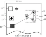
The image capturing assembly 400 is disposed on the base 100 and located at the camera scanning station c. Referring to fig. 14 and 16, in one embodiment, the image capturing assembly 400 includes a sensor pose adjustment mechanism 410 and one or more 3D cameras, two 3D cameras being exemplified in fig. 14 and 16, including 3D cameras 421 and 422. The 3D camera is arranged on the sensor pose adjusting mechanism 410, the sensor pose adjusting mechanism 410 is used for fixing one or more 3D cameras, the pose of the 3D cameras is convenient to adjust, the welding seam can be always in the visual field range scanned by the 3D cameras in the battery rotating process, and the influence of the stray light of the laser on the imaging quality is eliminated. Referring to fig. 16, in an embodiment, the sensor pose adjustment mechanism 410 enables the 3D camera to perform position adjustment along the X direction and the Z direction thereof to scan the annular weld at different positions, wherein the X direction is perpendicular to the optical axis of the 3D camera, and the Z direction is along the optical axis of the 3D camera. For example, in fig. 16, the 3D camera 421 can be used to capture an image of a weld at the edge position of the side surface of the battery case or the corner position of the battery after being adjusted in posture, and the 3D camera 422 can be used to capture an image of a weld at the edge position of the cover after being adjusted in posture. After the battery is transferred to the lower side of the 3D camera by the battery transfer mechanism 200, the battery rotation mechanism 600 drives the battery to rotate, the 3D camera can scan and collect height information of the surface of the battery including a complete annular weld, and the 3D camera collects height data of the surface of the annular weld by an encoder signal provided by the rotary servo motor 610 to obtain a height image.
The processor 500 is connected with each 3D camera, and is configured to acquire a height image of the surface of the battery scanned by each 3D camera, and execute the high-precision defect detection method for the annular weld provided by the present application to detect whether the annular weld on the battery has a defect. The Processor 500 may be a Central Processing Unit (CPU), other general-purpose Processor, a Digital Signal Processor (DSP), an Application Specific Integrated Circuit (ASIC), or the like. A general purpose processor may be a microprocessor or any conventional processor or the like. The steps of a method provided in connection with the present application may be embodied directly in a hardware processor, or in a combination of the hardware and software modules included in the processor. For example, the processor 500 may run upper computer software, and the upper computer software acquires a height image from the 3D camera for defect detection.
The following describes an operation flow of the high-precision defect detection apparatus for an annular weld in an embodiment of the present application with reference to fig. 14:
after laser welding is finished on a shell cover and a shell of a columnar battery, the battery is taken and placed on the battery transferring mechanism 200 at a feeding station by a manipulator and is fixed by a battery rotating shaft 620, for example, when the battery rotating shaft 620 is a vacuum adsorption rotating shaft, the battery is tightly adsorbed by the vacuum adsorption rotating shaft; then the battery is conveyed to a centering station II by the battery transferring mechanism 200, and the battery is centered by the centering mechanism 300; then the battery transferring mechanism 200 conveys the battery to a camera scanning station III, the rotary servo motor 610 drives the battery to rotate 360 degrees, and the 3D camera scans and acquires height images of the surface of the battery comprising the annular welding seam; after the height image of the battery surface is collected, the battery is conveyed to a blanking station (IV) by a battery transfer mechanism (200); the processor 500 acquires and processes the height image of the surface of the battery acquired by the 3D camera, detects whether the annular weld of the battery has a defect, and outputs a determination result.
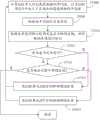
The high-precision defect detection method for the annular welding seam is described below. Referring to FIG. 17, in one embodiment, the method includes steps 1710-1760, which are described in detail below.
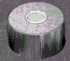
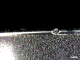
Step 1710: a height image of the surface of the battery is acquired. The height image of the battery surface can be taken by a 3D camera in the above-described device. The acquired height image may be a height image of the side of the battery case and/or the case cover depending on the position where the 3D camera is set. One line of height data can be obtained by one-time scanning of the 3D camera, and the height data can be obtained by one-time rotation of the batteryNLine height data, thisNThe line height data forming a height image, e.g. a pictureAs shown in fig. 18, 4 indicates a certain line of height data in the height image, and 5 indicates a weld region.
Step 1720: and acquiring a non-welding seam area in the height image, fitting by using height data in the non-welding seam area to obtain a reference height, and performing height calibration on the height image based on the reference height. The 3D camera shakes due to the vibration of the equipment during operation, and the scanned height image is wavy in a partial area, so that height calibration is needed, the influence of the equipment vibration on detection is reduced, and the false detection rate is reduced. Referring to FIG. 19, in one embodiment, the height calibration may include steps 1721-1724, as described in detail below.
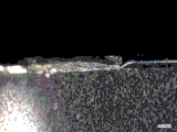
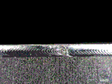
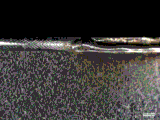
Step 1721: a column of height data (in the Y direction of the scanning direction of the camera) is selected from a non-soldered area, which is generally located at the side of the housing or at the central area of the housing cover, and 6 in fig. 18 indicates the selected column of height data.
Step 1722: and performing curve fitting on the selected column of height data to obtain a fitting curve. Fig. 18 shows a fitted curve at 7, which is a smooth curve, and since the concentricity of the columnar cell itself and the concentricity during rotation are deviated, the fitted curve is not a straight line but a smooth curve similar to that shown in fig. 18. The black dots represented by 8 in fig. 18 represent the raw height data and 9 represents the wave zone affected by the vibration of the equipment.
Step 1723: taking the height value on the fitting curve as a reference height, and calculating the difference value between the height data of each row and the corresponding reference height in the selected row of height datad i WhereiniIs shown asiAnd (6) rows.
Step 1724: for each line of height data in the height image, a calculation is madeZ ij +d i As new height data, a height-calibrated height image is thus obtained, whereinZ ij Is shown asiGo to the firstjHeight data of the column.
Step 1730: and calculating and marking a defect map of the height image after the height calibration. In the weld joint area, the height change of the weld joint surface with good welding is gentle, when the weld joint surface has defects such as explosion points, broken welding, pinholes, collisions, welding slag, non-metallic foreign bodies and the like, the height data of the weld joint has sudden changes, whether a certain area has the height sudden changes can be judged by comparing with an adjacent area, and therefore whether the area is a defect area is determined, and the process is called as defect map calculation and marking. Only the height data of the weld area is processed, since only the defects of the weld surface need to be detected. The weld Region may be obtained by artificially setting a Region of Interest (ROI), or by semantic segmentation or binarization. The user can select in advance which direction to compare, and the comparison direction is divided into three directions of X direction, Y direction and XY direction. In the defect map calculation and marking, firstly, a weld joint area in a height image after height calibration is obtained, then an area with a preset size is taken as a comparison unit according to a preset step length, a defect distinguishing step is executed on the comparison unit until the whole weld joint area is traversed, in the defect distinguishing step, the difference value of the comparison unit is calculated according to the average value of the height data in the comparison unit and the average value of the height data in the area which has the same size with the comparison unit and has a preset distance with the comparison unit in a preselected comparison direction, and finally, whether the comparison unit is a defect area is judged according to the difference value, and marks the defective area.
The initial position of traversal can be the upper left corner, the upper right corner, the lower left corner, the lower right corner, etc. of the weld joint region, and the traversal sequence can be along the X direction and then the Y direction, or along the Y direction and then the X direction, without limitation. In one embodiment, the comparison unit may be a rectangular area having a length in the X directionL x A length of each pixel in Y directionL y Pixel by pixel, with a step size in X directionS x One pixel, step size in Y direction isS y A plurality of pixels, each of which is a pixel,the following description will take the starting position as the upper left corner of the weld region (i.e. from the first row and the first column of the calibrated weld region image), and the traversal order is first along the X direction and then along the Y direction as an example.
Referring to FIG. 20, when the comparison direction is the X direction, the defect map calculation and labeling includes steps 17301 to 17307, which are described in detail below.
Step 17301: calculating an average of the height data in the comparison unitH i1The predetermined distance value is taken asS x For each pixel, calculating the distance from the comparison unit in the X directionS x Average value of height data of front and rear two rectangular regions having the same shape for each pixelH i2AndH i3as shown in FIG. 21, hereiIs shown asiA comparison unit. When the comparison unit exceeds the boundary of the welding seam region, mirror symmetry expansion is carried out to fill the part of the comparison unit exceeding the welding seam region, for example, when traversing to the row tail or the column tail, the comparison unit may exceed the welding seam region, and a part of the comparison unit is located outside the welding seam region, mirror symmetry expansion is carried out to fill the height data of the part, so that complete height data can be used for calculating the average valueH i1. In the following, a mirror symmetry extension is described as an example, for example, the comparison unit is located at the end of the row, beyond the weld area, and the weld area has a total of 200 columns, then the height data of column 199 is used as the height data of column 201, the height data of column 198 is used as the height data of column 202, and so on, so as to fill the comparison unit.
The average value isH i2AndH i3it is not always possible to calculate, for example, when the comparison unit is at the head of the line of the weld image, the distance in front of the comparison unit cannot be obtainedS x Rectangular area of pixel, at this timeH i2Is absent; when the comparison unit is positioned at the tail of the line of the weld seam region image, the distance behind the comparison unit cannot be obtainedS x Rectangular area of pixel, at this timeH i3Is absent.
Step 17302: computingSub i1=︱H i2-H i1An| andSub i2=︱H i3-H i1| and taking difference value deltaH i =Max(Sub i1,Sub i2) (ii) a When mean valueH i2If not, the difference value delta is takenH i =Max(H i1,H i3) When average value ofH i3If not, the difference value delta is takenH i =Max(H i1,H i2)。
Step 17303: the difference value deltaH i And a preset defect mark thresholdHMaking a comparison ifH i ≥HThen the comparing unit is judged as a defective area and the defective area is marked.
Step 17304: and judging whether the current row is traversed, if so, executing a step 17305, and otherwise, executing a step 17306.
Step 17305: and judging whether the whole welding seam area is traversed, if so, finishing the calculation, and otherwise, executing a step 17307.
Step 17306: moving the comparison unit in the X directionS x And returning to the step 17301.
Step 17307: moving the comparison unit in the Y directionS y And returning to the step 17301.
Referring to FIG. 22, when the comparison direction is the Y direction, the defect map calculation and labeling includes steps 17308-17314, which are described in detail below.
Step 17308: calculating an average of the height data in the comparison unitH i1The predetermined distance value is taken asS y One pixel, then calculate the distance from the comparison unit in the Y directionS y Average value of height data of upper and lower rectangular regions having the same shape for each pixelH i4AndH i5as shown in FIG. 23, hereiIs shown asiA comparison unit. Likewise, when the comparison unit exceeds the boundary of the weld region, mirror-symmetric expansion is performed to fill the portion of the comparison unit that exceeds the weld region.
Same, mean valueH i4AndH i5it is not always possible to calculate, for example, when the comparison unit is at the head of the weld image, the distance above the comparison unit cannot be obtainedS y Rectangular area of pixel, at this timeH i4Is absent; when the comparison unit is positioned at the tail of the column of the weld seam region image, the distance below the comparison unit cannot be obtainedS y Rectangular area of pixel, at this timeH i5Is absent.
Step 17309: computingSub i1=︱H i4-H i1An| andSub i2=︱H i5-H i1| and taking difference value deltaH i =Max(Sub i1,Sub i2) (ii) a When mean valueH i4If not, the difference value delta is takenH i =Max(H i1,H i5) When average value ofH i5If not, the difference value delta is takenH i =Max(H i1,H i4)。
Step 17310: the difference value deltaH i And a preset defect mark thresholdHMaking a comparison ifH i ≥HThen the comparing unit is judged as a defective area and the defective area is marked.
Step 17311: it is determined whether the current row is traversed, if so, step 17312 is performed, otherwise, step 17313 is performed.
Step 17312: and judging whether the whole welding seam area is traversed, if so, finishing the calculation, and otherwise, executing a step 17314.
Step 17313: moving the comparison unit in the X directionS x And returning to step 17308.
Step 17314: moving the comparison unit in the Y directionS y And returning to step 17308.
Referring to FIG. 24, when the comparison direction is XY, the defect map calculation and marking includes steps 17315 to 17321, which are described in detail below.
Step 17315: calculating an average of the height data in the comparison unitH i1Taking the distance value in the X direction asS x A distance value in the Y direction of each pixelS y A pixel for calculating the distance from the comparison unit in the X directionS x Average value of height data of front and rear two rectangular regions having the same shape for each pixelH i2AndH i3in the Y direction from the comparison unitS y Average value of height data of upper and lower rectangular regions having the same shape for each pixelH i4AndH i5as shown in FIG. 25, hereiIs shown asiA comparison unit. Likewise, when the comparison unit exceeds the boundary of the weld region, mirror-symmetric expansion is performed to fill the portion of the comparison unit that exceeds the weld region.
Same, mean valueH i2、H i3、H i4AndH i5it is not always possible to calculate, for example, when the comparison unit is at the head of the line of the weld image, the distance in front of the comparison unit cannot be obtainedS x Rectangular area of pixel, at this timeH i2Is absent; when the comparison unit is located at the head of the weld region image, the distance above the comparison unit cannot be obtainedS y Rectangular area of pixel, at this timeH i4Is absent.
Step 17316: according to the mean value
H i1、
H i2And
H i3calculating a difference value in the X direction
Sub i1When is coming into contact with
H i2In the absence thereof, is based on
H i1And
H i3calculating a difference value in the X direction
Sub i1When is coming into contact with
H i3In the absence thereof, is based on
H i1And
H i2calculating a difference value in the X direction
Sub i1(ii) a According to the mean value
H i1、
H i4And
H i5calculating the difference value in the Y direction
Sub i2When is coming into contact with
H i4In the absence thereof, is based on
H i1And
H i5calculating the difference value in the Y direction
Sub i2When is coming into contact with
H i5In the absence thereof, is based on
H i1And
H i4calculating the difference value in the Y direction
Sub i2. Taking the difference value
。
In one embodiment, the difference value can be calculated in the following mannerSub i1AndSub i2:
when is coming into contact with
H i2In the absence of the current, then
When is coming into contact with
H i3In the absence of the current, then
;
When is coming into contact with
H i4In the absence of the current, then
When is coming into contact with
H i5In the absence of the current, then
。
Step 17317: the difference value deltaH i And a preset defect mark thresholdHMaking a comparison ifH i ≥HThen the comparing unit is judged as a defective area and the defective area is marked.
Step 17318: it is determined whether the current row has been traversed, if so, step 17319 is performed, otherwise, step 17320 is performed.
Step 17319: and judging whether the whole welding seam area is traversed, if so, finishing the calculation, and otherwise, executing a step 17321.
Step 17320: moving the comparison unit in the X directionS x And returning to the step 1731.
Step 17321: moving the comparison unit in the Y directionS y And returning to the step 1731.
The calculation process when other starting positions and traversal orders are adopted is similar to this, and is not described herein again.
Step 1740: and calculating a defect severity map. The defect severity map is obtained by mapping an original height image into a three-channel RGB color map, the defect severity can be visually displayed, and the defect where on a welding line is more severe can be more intuitively displayed. The calculation process is as follows:
firstly, all pixels in the comparison unit are mapped into gray values in the range of 0-255, namely, the gray values are taken
WhereinG i Is as followsiThe gray values of all pixels in a unit of comparison,Max(ΔH i ) AndMin(ΔH i ) The maximum value and the minimum value of the difference values of all the comparison units are respectively.
Then the height data and gray value in the comparison unit are weighted and mapped into an RGB color image, namely the defect severity image: calculate the range of height data and gray values for all comparison cells:
whereinMax(h i ) AndMin(h i ) Respectively the maximum and minimum of the height data of all comparison units,Max(G i ) AndMin(G i ) Respectively the maximum and minimum of the grey values of all comparison cells. The height data and gray values are subjected to 1: 1 weighted to calculate color mapping values:
whereinh i Is as followsiThe height data in each comparison unit.
And searching the corresponding RGB value in the pseudo-color image lookup table according to the color mapping value, and mapping each comparison unit into an RGB color image so as to obtain a defect severity map.
Step 1750: and judging the result according to the marked defect area. Performing distance connectivity analysis on the marked defect region to enable the distance to be smaller than a set distance threshold valueDMerging the defect regions, calculating the area of the merged defect region, and presetting a defect area thresholdSWhen the area of the defect area after merging is larger than the preset defect area threshold valueSJudging that the annular welding seam has defects, otherwise judging that the annular welding seam is well welded, and when judging that the annular welding seam has defects, increasing the area to be larger than the defect area threshold valueSThe combined defect area is used as a welding defect area, and the welding defect area is calculatedThe position coordinates of the weld defect region.
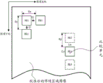
The distance between the defective regions can be represented by the distance of the center of gravity between them, as shown in fig. 26, in which 10 denotes a comparison unit, 11 denotes a defect of the bead surface, 12 denotes a region marked as a defective region, 13 denotes the position of the center of gravity of the defective region, 14 denotes the distance between the centers of gravity of two defective regions, and 15 denotes the merged defective region. When merging, the barycentric coordinates of each defect area are calculatedg(x i ,y i ) Then calculating the distance between the centers of gravity of the two defect regionsdIf, ifd≤DThe two defective areas are merged, hereiIs shown asiAnd (4) a defective area. The difference value delta can be adjustedH i The defect amount is used for quantitative evaluation of defects, and the defect amount of the combined defect areaS i =∑ΔH i 。
In order to obtain the position coordinates of the welding defective region, the center of gravity coordinates of the combined defective region may be calculated as the position coordinates of the welding defective region. As shown in fig. 27, the welding defective region 17 is a combination of 3 defective regions, and the coordinates of the center of gravity 16 are set as the position coordinates thereof. The calculation process is as follows:
calculating the sum of gray values in each defect region before merging
;
Calculating weighting coefficients of each defect area before merging
;
Calculating barycentric coordinates of the merged defect regions
G(
x j ,
y j ) As position coordinates of the welding defect region, wherein
W i Is shown as
iThe sum of the gray values in the individual defect regions,
ρ i is shown as
iThe weighting coefficients of the individual defective areas are,
,
is shown as
iThe abscissa of the center of gravity of each defective region,
is shown as
iThe ordinate of the center of gravity of the individual defect region,
jis shown as
jAnd welding defect areas.
Step 1760: and outputting the judgment result and the defect severity map, and also outputting the position coordinates of the welding defect area when the annular welding seam is judged to have defects.
The determination result can be output to a Programmable Logic Controller (PLC), and the PLC controls the mechanical gripper to take the battery off from the battery transfer mechanism 200, and place the good products and the defective products in a classified manner.
The high-precision defect detection method and device for the annular welding seam have the following advantages:
(1) the application provides a high accuracy defect detection device of cyclic annular welding seam can imbed the assembly line of current column or button form battery, realizes full-automatic equipment and the on-line measuring of battery, has realized the automated production of battery in the true sense, has improved production efficiency. The sensor pose adjusting mechanism and the centering mechanism in the device enable the annular welding line to be within the visual field range of the 3D camera all the time, and effective collection of welding line height data is guaranteed.
(2) The existing annular welding seam surface defect detection mainly depends on manual work to carry out visual inspection by using a CCD microscope, is influenced by illumination and subjectivity of operators, and small-sized defect products cannot be detected, so that the condition of serious omission is caused.
(3) The high-precision defect detection method for the annular welding line provided by the application can be used for carrying out height calibration on the annular welding line after a height image is acquired, correcting the influence caused by shaking of the running equipment, reducing the false detection rate and improving the stability of defect detection.
(4) The defect map calculation method and the defect marking method adopted in the high-precision defect detection method of the annular welding line can stably calculate the position and the area of the defect.
(5) According to the high-precision defect detection method for the annular welding line, the original height image is mapped into the RGB color image with three channels, the defect severity map is obtained, the defect severity can be visually displayed, and the defect severity of each part on the welding line can be more visually displayed.
In summary, the high-precision defect detection method and device for the annular welding seam effectively improve the detection efficiency and the detection accuracy of the surface defects of the annular welding seam.
Those skilled in the art will appreciate that all or part of the functions of the various methods in the above embodiments may be implemented by hardware, or may be implemented by computer programs. When all or part of the functions of the above embodiments are implemented by a computer program, the program may be stored in a computer-readable storage medium, and the storage medium may include: a read only memory, a random access memory, a magnetic disk, an optical disk, a hard disk, etc., and the program is executed by a computer to realize the above functions. For example, the program may be stored in a memory of the device, and when the program in the memory is executed by the processor, all or part of the functions described above may be implemented. In addition, when all or part of the functions in the above embodiments are implemented by a computer program, the program may be stored in a storage medium such as a server, another computer, a magnetic disk, an optical disk, a flash disk, or a removable hard disk, and may be downloaded or copied to a memory of a local device, or may be version-updated in a system of the local device, and when the program in the memory is executed by a processor, all or part of the functions in the above embodiments may be implemented.
The present invention has been described in terms of specific examples, which are provided to aid understanding of the invention and are not intended to be limiting. For a person skilled in the art to which the invention pertains, several simple deductions, modifications or substitutions may be made according to the idea of the invention.