CN114088713A - Be applied to micro-observation device of fatigue fracture experiment - Google Patents
Be applied to micro-observation device of fatigue fracture experiment Download PDFInfo
- Publication number
- CN114088713A CN114088713A CN202111553735.3A CN202111553735A CN114088713A CN 114088713 A CN114088713 A CN 114088713A CN 202111553735 A CN202111553735 A CN 202111553735A CN 114088713 A CN114088713 A CN 114088713A
- Authority
- CN
- China
- Prior art keywords
- moving mechanism
- driving motor
- microscopic observation
- clamp
- optical axis
- Prior art date
- Legal status (The legal status is an assumption and is not a legal conclusion. Google has not performed a legal analysis and makes no representation as to the accuracy of the status listed.)
- Granted
Links
Images




Classifications
-
- G—PHYSICS
- G01—MEASURING; TESTING
- G01N—INVESTIGATING OR ANALYSING MATERIALS BY DETERMINING THEIR CHEMICAL OR PHYSICAL PROPERTIES
- G01N21/00—Investigating or analysing materials by the use of optical means, i.e. using sub-millimetre waves, infrared, visible or ultraviolet light
- G01N21/84—Systems specially adapted for particular applications
-
- G—PHYSICS
- G01—MEASURING; TESTING
- G01N—INVESTIGATING OR ANALYSING MATERIALS BY DETERMINING THEIR CHEMICAL OR PHYSICAL PROPERTIES
- G01N21/00—Investigating or analysing materials by the use of optical means, i.e. using sub-millimetre waves, infrared, visible or ultraviolet light
- G01N21/01—Arrangements or apparatus for facilitating the optical investigation
-
- G—PHYSICS
- G01—MEASURING; TESTING
- G01N—INVESTIGATING OR ANALYSING MATERIALS BY DETERMINING THEIR CHEMICAL OR PHYSICAL PROPERTIES
- G01N3/00—Investigating strength properties of solid materials by application of mechanical stress
- G01N3/32—Investigating strength properties of solid materials by application of mechanical stress by applying repeated or pulsating forces
-
- G—PHYSICS
- G02—OPTICS
- G02B—OPTICAL ELEMENTS, SYSTEMS OR APPARATUS
- G02B21/00—Microscopes
- G02B21/24—Base structure
- G02B21/26—Stages; Adjusting means therefor
-
- G—PHYSICS
- G01—MEASURING; TESTING
- G01N—INVESTIGATING OR ANALYSING MATERIALS BY DETERMINING THEIR CHEMICAL OR PHYSICAL PROPERTIES
- G01N2203/00—Investigating strength properties of solid materials by application of mechanical stress
- G01N2203/0058—Kind of property studied
- G01N2203/0069—Fatigue, creep, strain-stress relations or elastic constants
- G01N2203/0073—Fatigue
-
- Y—GENERAL TAGGING OF NEW TECHNOLOGICAL DEVELOPMENTS; GENERAL TAGGING OF CROSS-SECTIONAL TECHNOLOGIES SPANNING OVER SEVERAL SECTIONS OF THE IPC; TECHNICAL SUBJECTS COVERED BY FORMER USPC CROSS-REFERENCE ART COLLECTIONS [XRACs] AND DIGESTS
- Y02—TECHNOLOGIES OR APPLICATIONS FOR MITIGATION OR ADAPTATION AGAINST CLIMATE CHANGE
- Y02E—REDUCTION OF GREENHOUSE GAS [GHG] EMISSIONS, RELATED TO ENERGY GENERATION, TRANSMISSION OR DISTRIBUTION
- Y02E30/00—Energy generation of nuclear origin
- Y02E30/30—Nuclear fission reactors
Landscapes
- Physics & Mathematics (AREA)
- Chemical & Material Sciences (AREA)
- Analytical Chemistry (AREA)
- General Physics & Mathematics (AREA)
- Health & Medical Sciences (AREA)
- Life Sciences & Earth Sciences (AREA)
- Biochemistry (AREA)
- General Health & Medical Sciences (AREA)
- Immunology (AREA)
- Pathology (AREA)
- Optics & Photonics (AREA)
- Microscoopes, Condenser (AREA)
Abstract
The invention relates to the technical field of experimental equipment, in particular to a microscopic observation device applied to a fatigue fracture experiment. The device comprises a clamp, a moving platform and a microscopic observation mechanism, wherein the clamp is used for being sleeved on an upright post, the moving platform is arranged on the clamp, and the microscopic observation mechanism is arranged on the moving platform and used for observing cracks on a test piece. Because the clamp cover is established on the stand, the height of clamp on the stand can be adjusted, because moving platform sets up on the clamp, when adjusting the height of clamp on the stand, can drive the moving platform motion simultaneously, adjusts the distance between moving platform and the experiment platform. From this, through adjusting the height of clamp on the stand, make and keep suitable distance between moving platform and the experiment platform, can guarantee to set up the microscopic observation mechanism on moving platform and can survey the test piece on the experiment platform, can prevent again that moving platform and other mechanisms from taking place to interfere.
Description
Technical Field
The invention relates to the technical field of experimental equipment, in particular to a microscopic observation device applied to a fatigue fracture experiment.
Background
In the fatigue fracture experiment process of the composite material, a test piece made of the composite material is arranged on an experiment platform. By applying a large load to the test piece, cracks may be generated on the surface of the test piece. And observing the cracks by using a microscopic observation device, obtaining related data and calculating so as to detect the mechanical property of the composite material.
In the above-mentioned experimental process, set up the microscopic observation device on the experiment platform usually, need occupy great space, and it produces interference with other experimental apparatus on the experiment platform easily, may lead to the observation result of microscopic observation device to the test piece to appear the error.
Disclosure of Invention
The invention solves the problem of how to avoid the interference between a microscopic observation device and other experimental devices.
In order to solve the problems, the invention provides a microscopic observation device applied to a fatigue fracture experiment, which comprises a hoop, a moving platform and a microscopic observation mechanism, wherein the hoop is used for being sleeved on an upright post, the moving platform is arranged on the hoop, and the microscopic observation mechanism is arranged on the moving platform and is used for observing cracks on a test piece.
Optionally, the moving platform includes a first moving mechanism, a second moving mechanism and a third moving mechanism, the first moving mechanism is disposed on the clamp, the first moving mechanism is vertically disposed, the second moving mechanism is connected to the first moving mechanism in a sliding manner along a vertical direction, the third moving mechanism is connected to the second moving mechanism in a sliding manner along a front-back direction, and the microscopic observation mechanism is connected to the third moving mechanism in a sliding manner along a left-right direction.
Optionally, the clamp is provided with two, two the clamp respectively with the upper and lower both ends of first moving mechanism are connected.
Optionally, the clamp includes two collars and a bolt, open sides of the two collars are disposed opposite to each other, and the bolt is disposed at a joint of the two collars.
Optionally, anti-slip filler is adapted to be disposed between the post and the clip.
Optionally, the first moving mechanism includes a first driving motor, a first screw rod, and a first connecting member, the first driving motor is disposed on the clamp, a transmission shaft of the first driving motor is vertically disposed, an end of the first screw rod is connected to the transmission shaft of the first driving motor, and the first connecting member is slidably connected to the first screw rod;
the second moving mechanism comprises a support, a second driving motor, a second screw rod and a second connecting piece, the support is arranged on the first connecting piece, the second driving motor is arranged on the support, a transmission shaft of the second driving motor is arranged along the front-back direction, the end part of the second screw rod is connected with the transmission shaft of the second driving motor, and the second connecting piece is connected to the second screw rod in a sliding manner; the third moving mechanism is arranged on the second connecting piece.
Optionally, first moving mechanism still includes optical axis support, first optical axis and first slider, the optical axis support sets up on the clamp, first slider sliding connection in first optical axis, first connecting piece includes first connecting block and second connecting block, first connecting block sliding connection in first lead screw, first connecting block with the second connecting block is connected, and is used for right first slider carries out the centre gripping, the second connecting piece with first connecting block is connected.
Optionally, the second moving mechanism further includes a second optical axis and a second slider, the second optical axis is disposed on the bracket, the second slider is slidably connected to the second optical axis, a clamping groove is formed in the second connecting member, and the second slider is disposed in the clamping groove.
Optionally, the third moving mechanism includes a third driving motor, a third lead screw, a third connecting piece and a guide rail, the guide rail is arranged along the left-right direction, the microscopic observation mechanism is arranged at one end of the guide rail, the third driving motor is arranged at the other end of the guide rail, a transmission shaft of the third driving motor is arranged along the left-right direction, the end of the third lead screw is connected with the transmission shaft of the third driving motor, the third connecting piece is connected with the second connecting piece, and the third connecting piece is slidably connected with the third lead screw.
Optionally, the microscopic observation device applied to the fatigue fracture experiment further comprises a control box, and the control box is in communication connection with the first driving motor, the second driving motor and the third driving motor.
The invention has the technical effects that: the clamp cover is established on the stand, and the height of clamp on the stand can be adjusted, because moving platform sets up on the clamp, when adjusting the height of clamp on the stand, can drive the moving platform motion simultaneously, adjusts the distance between moving platform and the experiment platform. From this, through adjusting the height of clamp on the stand, make and keep suitable distance between moving platform and the experiment platform, can guarantee to set up the microscopic observation mechanism on moving platform and can survey the test piece on the experiment platform, can prevent again that moving platform and other mechanisms from taking place to interfere. Simultaneously, because the stand sets up on the ground, stability is stronger to guarantee that the cover establishes the clamp on the stand and the stability of the moving platform of setting on the clamp, and then guarantee the stability of the micro-observation mechanism of setting on moving platform, prevent that micro-observation mechanism from producing the displacement because of the disturbance, avoid influencing the observation data. In addition, the clamp sets up on the stand, rotates the clamp, can adjust microscopic observation mechanism's angle, is convenient for aim at the test piece with microscopic observation mechanism's the field of vision fast.
Drawings
FIG. 1 is a schematic structural diagram of a microscopic observation device applied to a fatigue fracture experiment according to an embodiment of the present invention;
FIG. 2 is a schematic structural view of a clamp according to an embodiment of the present invention;
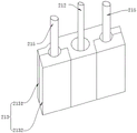
FIG. 3 is a schematic structural diagram of a first connecting member according to an embodiment of the present invention;
FIG. 4 is a schematic structural diagram of a connecting plate according to an embodiment of the present invention;
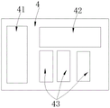
FIG. 5 is a schematic diagram of the internal structure of the control box according to the embodiment of the present invention;
fig. 6 is a schematic external structural diagram of a control box according to an embodiment of the present invention.
Reference numerals:
1. clamping a hoop; 11. a collar; 21. a first moving mechanism; 211. a first drive motor; 212. a first lead screw; 213. a first connecting member; 214. a first optical axis mount; 215. a first optical axis; 22. a second moving mechanism; 221. a support; 222. a second drive motor; 223. a second lead screw; 224. a second connecting member; 2241. a card slot; 225. a second optical axis mount; 226. a second optical axis; 23. a third moving mechanism; 231. a third drive motor; 232. a third screw rod; 233. a guide rail; 234. a connecting plate; 2341. a first connection region; 2342. a second attachment zone; 2343. a third attachment zone; 235. a third slider; 3. a microscopic observation mechanism; 4. a control box; 41. a power source; 42. a single chip microcomputer; 43. a motor drive plate; 441. a raise button; 442. a down button; 443. a forward movement button; 444. a backward movement button; 445. a right shift button; 446. a left shift button; 45. a speed adjusting knob; 46. and a power indicator lamp.
Detailed Description
In order to make the aforementioned objects, features and advantages of the present invention comprehensible, embodiments accompanied with figures are described in detail below.
XYZ coordinate axes are provided herein wherein a forward direction of the X axis represents a forward direction, a reverse direction of the X axis represents a rearward direction, a forward direction of the Y axis represents a left direction, a reverse direction of the Y axis represents a right direction, a forward direction of the Z axis represents an upward direction, and a reverse direction of the Z axis represents a downward direction.
In order to solve the technical problem, as shown in fig. 1, an embodiment of the invention discloses a microscopic observation device applied to a fatigue fracture experiment, which comprises a hoop 1, a moving platform and a microscopic observation mechanism 3, wherein the hoop 1 is used for being sleeved on an upright post, the moving platform is arranged on the hoop 1, and the microscopic observation mechanism 3 is arranged on the moving platform and is used for observing cracks on a test piece.
The stand column is vertically arranged on the foundation and used for supporting the experiment platform, and part of the stand column penetrates through the experiment platform and is located above the experiment platform. The test piece sets up on experiment platform, and clamp 1 sets up on the stand that is located experiment platform top. The microscopic observation mechanism 3 comprises a microscope and a camera, the camera is connected with an ocular lens of the microscope, and an objective lens of the microscope is used for aligning the test piece. The clamp 1 and the upright post can be connected in an interference fit manner.
In this embodiment, when the mobile platform is directly disposed on the experiment platform, or the distance between the mobile platform and the experiment platform is small, the mobile platform is easily interfered with other experiment mechanisms on the experiment platform; and when the distance between the mobile platform and the experiment platform is large, the limiting observation mechanism arranged on the mobile platform is difficult to observe the test piece arranged on the experiment platform. Because clamp 1 cover is established on the stand, the height of clamp 1 on the stand can be adjusted, because moving platform sets up on clamp 1, when adjusting the height of clamp 1 on the stand, can drive the moving platform motion simultaneously to adjust the distance between moving platform and the experiment platform.
To sum up, because clamp 1 cover is established on the stand, the height of clamp 1 on the stand can be adjusted, because moving platform sets up on clamp 1, when adjusting the height of clamp 1 on the stand, can drive the moving platform motion simultaneously, adjusts the distance between moving platform and the experiment platform. From this, through adjusting the height of clamp 1 on the stand, make and keep suitable distance between moving platform and the experiment platform, can guarantee to set up microscopic observation mechanism 3 on moving platform and can survey the test piece on the experiment platform, can prevent again that moving platform and other mechanisms from taking place to interfere. Meanwhile, the stand column is arranged on the foundation, so that the stability is high, the stability of the clamp 1 arranged on the stand column and the stability of the moving platform arranged on the clamp 1 are guaranteed, the stability of the microscopic observation mechanism 3 arranged on the moving platform is guaranteed, the microscopic observation mechanism 3 is prevented from generating displacement due to disturbance, and the observation data are prevented from being influenced. In addition, clamp 1 sets up on the stand, rotates clamp 1, can adjust microscopic observation mechanism 3's angle, is convenient for aim at the test piece with microscopic observation mechanism 3's the field of vision fast.
Optionally, as shown in fig. 1, the moving platform includes a first moving mechanism 21, a second moving mechanism 22, and a third moving mechanism 23, the first moving mechanism 21 is disposed on the clamp 1, the first moving mechanism 21 is disposed vertically, the second moving mechanism 22 is slidably connected to the first moving mechanism 21 in the vertical direction, the third moving mechanism 23 is slidably connected to the second moving mechanism 22 in the front-back direction, and the microscopic observation mechanisms 3 are slidably connected to the third moving mechanism 23 in the left-right direction.
Wherein the test piece is arranged on the right side of the microscopic observation mechanism 3.
In this embodiment, the first moving mechanism 21 is vertically disposed, and when the second moving mechanism 22 slides relative to the first moving mechanism 21, the second moving mechanism 22 moves along the vertical direction, and since the third moving mechanism 23 is disposed on the second moving mechanism 22, the microscopic observation mechanism 3 is disposed on the third moving mechanism 23, and when the second moving mechanism 22 moves along the vertical direction, the third moving mechanism 23 and the microscopic observation mechanism 3 can be driven to move along the vertical direction. Similarly, the second moving mechanism 22 is arranged along the front-back direction, and when the third moving mechanism 23 slides relative to the second moving mechanism 22, the third moving mechanism 23 moves along the front-back direction, and since the microscopic observation mechanism 3 is arranged on the third moving mechanism 23, the third moving mechanism 23 moves along the front-back direction, so that the microscopic observation mechanism 3 can be driven to move along the front-back direction. In the process that the microscopic observation mechanism 3 moves along the vertical direction and the front-back direction, the visual field of the microscopic observation mechanism 3 can be accurately aligned to a specific position on the test piece, so that the test piece can be observed conveniently.
Meanwhile, the third moving mechanism 23 is arranged in the left-right direction, and when the microscopic observation mechanism 3 slides relative to the third moving mechanism 23, the microscopic observation mechanism 3 moves in the left-right direction. In the process that the microscopic observation mechanism 3 moves along the front-back direction, the linear distance between the microscopic observation mechanism 3 and the test piece can be adjusted so as to ensure the definition of the visual field of the microscopic observation mechanism 3.
Alternatively, as shown in fig. 1, two clamps 1 are provided, and the two clamps 1 are connected to upper and lower ends of the first moving mechanism 21, respectively.
Wherein, two clamps 1 all overlap and establish on the stand.
Since the second moving mechanism 22 is provided on the first moving mechanism 21, the third moving mechanism 23 is provided on the second moving mechanism 22, and the microscopic observation mechanism 3 is provided on the third moving mechanism 23, the first moving mechanism 21 simultaneously carries the second moving mechanism 22, the third moving mechanism 23, and the microscopic observation mechanism 3. When only one clamp 1 is arranged, the first moving mechanism 21 is in a cantilever structure, and the second moving mechanism 22, the third moving mechanism 23 and the microscopic observation mechanism 3 are arranged on the first moving mechanism 21, so that an eccentric load is easily generated on the first moving mechanism 21, which causes deformation of the first moving mechanism 21, and the structures of the second moving mechanism 22, the third moving mechanism 23 and the microscopic observation mechanism 3 are unstable, which affects the accuracy of the observation data of the microscopic observation mechanism 3.
In this embodiment, two clamps 1 are provided on the column, and the upper and lower ends of the first moving mechanism 21 are connected to one of the clamps 1, respectively, so that the upper and lower ends of the first moving mechanism 21 can be simultaneously assembled to the column. From this, set up two clamps 1 on the stand to connect the upper and lower both ends of first moving mechanism 21 with one of them clamp 1 respectively, can promote the rigidity of first moving mechanism 21, second moving mechanism 22, third moving mechanism 23 and microscopic observation mechanism 3 set up on first moving mechanism 21, are difficult to make first moving mechanism 21 take place to warp, thereby guarantee the structural stability of second moving mechanism 22, third moving mechanism 23 and microscopic observation mechanism 3, and then guarantee the accuracy of the observed data of microscopic observation mechanism 3.
Preferably, the band 1 is made of nylon material.
In this embodiment, since the clamp 1 needs to bear the entire weight of the moving platform, when the strength of the clamp 1 is small, the clamp is easily broken, so that the stability of the moving platform is damaged, the stability of the microscopic observation mechanism 3 is further damaged, and the accuracy of the observation data of the microscopic observation mechanism 3 is affected. Adopt nylon materials to make clamp 1, the intensity of clamp 1 is great, even bear moving platform's whole weight, also is difficult to the fracture to guaranteed moving platform's stability, and then guaranteed the stability of microscopic observation mechanism 3 and the accuracy of the observation data of microscopic observation mechanism 3.
Alternatively, as shown in fig. 2, the yoke 1 includes two collars 11 and a bolt, open sides of the two collars 11 are disposed opposite to each other, and the bolt is disposed at a junction of the two collars 11.
Wherein, threaded holes are arranged on the lantern ring 11 for bolts to pass through. When two lantern rings 11 set up relatively, the screw hole coaxial distribution on two lantern rings 11, the bolt passes two screw holes in proper order to use the nut fastening at the other end. Meanwhile, both the collars 11 are formed in a semicircular shape. In addition, a spring washer is arranged on the bolt and is positioned between the nut and the lantern ring 11.
In this embodiment, two collars 11 are oppositely arranged on the column and threaded through the threaded holes using bolts to connect the two collars 11. When observing the test piece in the experimentation, screw up the bolt, increased the frictional force between the lantern ring 11 and the stand, prevent that the lantern ring 11 from sliding on the stand, promoted the stability of clamp 1, and then promoted the stability of micro-observation mechanism 3. When the height of the clamp 1 on the stand column is adjusted, the bolt is loosened, so that the friction force between the lantern ring 11 and the stand column is reduced, the lantern ring 11 can conveniently slide on the stand column, and the height of the clamp 1 on the stand column can be easily adjusted.
Optionally, anti-slip filler is suitably provided between the stud and the clip 1.
Wherein, the anti-skid filler comprises fillers with rough surfaces, such as paper tapes, electrical tapes and the like.
In this embodiment, because the contact surface between stand and the clamp 1 is comparatively smooth, coefficient of friction is less, and frictional force is less, and clamp 1 cover is established and is probably taken place to slide on the stand, influences moving platform's stability. Before clamp 1 is established to the cover, set up coarse fillers such as sticky tape and electrician's adhesive tape in advance on the stand, later, when clamp 1 is established to the cover, clamp 1 cover is established and is provided with the region of coarse fillers such as sticky tape and electrician's adhesive tape on the stand, and the coefficient of friction between coarse fillers such as clamp 1 sticky tape, electrician's adhesive tape is great, and frictional force is also great, can prevent that clamp 1 from sliding on the stand, is convenient for guarantee moving platform's stability.
Alternatively, as shown in fig. 1, the first moving mechanism 21 includes a first driving motor 211, a first lead screw 212, and a first connecting member 213, the first driving motor 211 is disposed on the clamp 1, a transmission shaft of the first driving motor 211 is vertically disposed, an end of the first lead screw 212 is connected with the transmission shaft of the first driving motor 211, and the first connecting member 213 is slidably connected to the first lead screw 212;
the second moving mechanism 22 includes a bracket 221, a second driving motor 222, a second screw rod 223 and a second connecting piece 224, the bracket 221 is disposed on the first connecting piece 213, the second driving motor 222 is disposed on the frame, a transmission shaft of the second driving motor 222 is disposed along the front-rear direction, an end of the second screw rod 223 is connected with the transmission shaft of the second driving motor 222, and the second connecting piece 224 is slidably connected to the second screw rod 223; the third moving mechanism 23 is provided on the second link 224.
Wherein, a first screw nut is arranged in the first connecting piece 213, the first screw nut is in threaded connection with the first screw 212, and the first screw 212 is vertically arranged. A second lead screw nut is arranged in the second connecting piece 224, the second lead screw nut is in threaded connection with a second lead screw 223, and the second lead screw 223 is horizontally arranged along the front-back direction.
In this embodiment, the first driving motor 211 is started to drive the first lead screw 212 to rotate, and since the first lead screw nut is in threaded connection with the first lead screw 212, the first lead screw nut moves along the extending direction of the first lead screw 212 in the rotating process of the first lead screw 212; since the first lead screw 212 is vertically disposed, the first lead screw nut moves in a vertical direction; since the first lead screw nut is arranged in the first connecting piece 213, the first connecting piece 213 can be driven to move along the vertical direction in the movement process of the first lead screw nut; meanwhile, since the bracket 221 is disposed on the first connecting member 213, the first connecting member 213 can drive the bracket 221 to move in a vertical direction during movement.
The second driving motor 222 is started to drive the second screw rod 223 to rotate, and because the second screw rod nut is in threaded connection with the second screw rod 223, the second screw rod nut moves along the extension direction of the second screw rod 223 in the rotation process of the second screw rod 223; since the second lead screw 223 is disposed in the front-rear direction, the second lead screw nut moves in the front-rear direction; because the second lead screw nut is arranged in the second connecting piece 224, the second connecting piece 224 can be driven to move along the front-back direction in the moving process of the second lead screw nut; meanwhile, since the third moving mechanism 23 is disposed on the second connecting member 224, the second connecting member 224 can drive the third moving mechanism 23 to move in the front-back direction during the movement process.
To sum up, the first driving motor 211 is started to drive the first connecting piece 213 to move along the vertical direction, and the first driving motor is arranged on the first connecting piece 213, so that the bracket 221 can be driven to move along the vertical direction; since the second connecting member 224 is disposed on the bracket 221, the second connecting member 224 can be driven to move in the vertical direction; since the third moving mechanism 23 is disposed on the second connecting member 224, the third moving mechanism 23 can be driven to move in the vertical direction; since the microscopic observation mechanism 3 is disposed on the third moving mechanism 23, the microscopic observation mechanism 3 can be driven to move in the vertical direction.
The second driving motor 222 is started to drive the second connecting piece 224 to move in the front-back direction, and the third moving mechanism 23 can be driven to move in the front-back direction because the third moving mechanism 23 is arranged on the second connecting piece 224; since the microscopic observation mechanism 3 is provided on the third moving mechanism 23, the microscopic observation mechanism 3 can be driven to move in the front-rear direction.
Optionally, as shown in fig. 1 and fig. 3, the first moving mechanism 21 further includes a first optical axis support 214, a first optical axis 215, and a first sliding block, the first optical axis support 214 is disposed on the yoke 1, the first sliding block is slidably connected to the first optical axis 215, the first connecting member 213 includes a first connecting block 2131 and a second connecting block 2132, the first connecting block 2131 is connected to the second connecting block 2132, the first connecting block 2131 is slidably connected to the first lead screw 212, and the first connecting block 2131 is connected to the second connecting block 2132 and is used for clamping the first sliding block.
Wherein, first optical axis support 214 is provided with two, and two first optical axis supports 214 respectively one-to-one set up on two clamps 1, and the both ends of first optical axis 215 are connected with two first optical axis supports 214 respectively, and first optical axis 215 is vertical to be set up. The first slider is positioned between the first connecting block 2131 and the second connecting block 2132, and the first connecting block 2131 and the second connecting block 2132 are connected by using a bolt.
In the present embodiment, the first optical axis 215 is set, and the first connecting member 213 can be guided during the movement of the first connecting member 213 in the vertical direction. Because the first connecting piece 213 needs to bear the weight of the second moving mechanism 22 and the third moving mechanism 23 at the same time, the torque is large, the first connecting piece 213 is provided with the first connecting block 2131 and the second connecting block 2132, the first connecting block 2131 and the second connecting block 2132 are connected through the bolt, because the first sliding block is arranged on the first connecting block 2131 and the second connecting block 2132, the bolt is tightened, the clamping force of the first connecting block 2131 and the second connecting block 2132 on the first sliding block can be increased, the separation of the first sliding block and the first connecting piece 213 is prevented, and therefore the stability of the structure of the first moving mechanism 21 is improved. Meanwhile, the clamping force of the first connecting block 2131 and the second connecting block 2132 on the first sliding block can be reduced by loosening the bolts, and the first sliding block and the first connecting piece 213 can be separated easily.
Optionally, as shown in fig. 1, the second moving mechanism 22 further includes a second optical axis support 225, a second optical axis 226, and a second slider, the second optical axis support 225 is disposed on the frame, the second optical axis 226 is disposed on the second optical axis support 225, the second slider is slidably connected to the second optical axis 226, a slot 2241 is disposed on the second connecting member 224, and the second slider is disposed in the slot 2241.
The second optical axis holders 225 are disposed at two ends of the frame, the two ends of the second optical axis 226 are connected to the two second optical axis holders 225, and the second optical axis 226 is disposed along the front and rear direction.
In the present embodiment, a second optical axis 226 is provided, and the second optical axis 226 can guide the second connecting member 224 during the movement of the second connecting member 224 in the front-back direction. Since the third moving mechanism 23 is provided on the second link 224, and a load is applied to the second link 224 mainly in the radial direction of the second optical axis 226, the tendency of relative movement between the second link 224 and the second slider in the radial direction of the second optical axis 226 is large. The slot 2241 is opened along the axial direction of the second optical axis 226, and the second slider is disposed in the slot 2241, that is, the second slider and the second connecting member 224 can only move along the axial direction of the second optical axis 226, and meanwhile, the trend of relative movement between the second connecting member 224 and the second slider along the axial direction of the second optical axis 226 is small. Therefore, the second sliding block is not easy to separate from the second connecting piece 224, the stability of the structure between the second sliding block and the second connecting piece 224 is ensured, and the stability of the structure of the second moving mechanism 22 is further improved.
Alternatively, as shown in fig. 1, the third moving mechanism 23 includes a third driving motor 231, a third lead screw 232, a third connecting member 233 and a guide rail 234, the guide rail 234 is disposed along the left-right direction, the microscopic observation mechanism 3 is disposed at one end of the guide rail 234, the third driving motor 231 is disposed at the other end of the guide rail 234, a transmission shaft of the third driving motor 231 is disposed along the left-right direction, an end of the third lead screw 232 is connected with the transmission shaft of the third driving motor 231, the third connecting member 233 is connected with the second connecting member 224, and the third connecting member 233 is slidably connected with the third lead screw 232.
In this embodiment, when the third driving motor 231 is started, the third lead screw 232 and the third connecting member 233 slide relatively to each other, so as to drive the guide rail 234 to move, thereby driving the microscopic observation mechanism 3 disposed at the right end of the guide rail 234 to move in the left-right direction. Because the test piece is arranged at the right end of the microscopic observation mechanism 3, when the microscopic observation mechanism 3 moves along the left-right direction, the distance between the microscopic observation mechanism 3 and the test piece can be adjusted, thereby realizing the adjustment of the visual field size of the microscopic observation mechanism 3. Meanwhile, the microscope observation mechanism 3 is provided at the end of the guide rail 234, so that the guide rail 234 can be prevented from blocking the view of the microscope observation mechanism 3. In addition, the right end of the guide rail 234 can be prevented from being close to the test piece for a long time, and interference of the guide rail 234 on other mechanisms on the experiment platform is prevented.
Preferably, as shown in fig. 1 and 4, the third connecting member 233 includes a connecting plate 235 and a third slider 236, the connecting plate 235 is provided with a first connecting region 2351 and a second connecting region 2352, the connecting position of the connecting plate 235 and the second connecting member 224 is located in the first connecting region 2351, and the third slider 236 is located in the second connecting region 2352.
The third connecting member 233 further includes a third lead screw nut, which is disposed on the connecting plate 235 and is in threaded connection with the third lead screw 232. Meanwhile, a third connection region 2353 is further arranged on the connection plate 235, the first connection region 2351 is positioned at two sides of the connection plate 235, the second connection region 2352 and the third connection region 2353 are both positioned in the middle of the connection plate 235, and the third lead screw nut is positioned in the third connection region 2353.
In this embodiment, by providing a first connection region 2351, a second connection region 2352, and a third connection region 2353 on the connection plate 235, the third slider 236 is disposed within the second connection region 2352, and a third lead screw nut is disposed within the third connection region 2353, while the connection of the third slider 236 and the connection plate 235 is disposed within the first connection region 2351. Therefore, the third slider 236, the third lead screw nut and the connecting plate 235 can be reasonably arranged, and the third slider 236, the third lead screw nut, the connecting plate 235 and the third connecting piece 233 can be assembled quickly.
Optionally, as shown in fig. 4 to 6, the microscopic observation device applied to the fatigue fracture experiment further includes a control box 4, and the control box 4 is connected in communication with the first driving motor 211, the second driving motor 222, and the third driving motor 231.
The control box 4 is internally provided with a power supply 41, a singlechip 42 and a motor driving plate 43, and the control box 4 is provided with an ascending button 441, a descending button 442, a forward moving button 443, a backward moving button 444, a right moving button 445, a left moving button 446, a speed adjusting knob 45 and a power indicator lamp 46.
In the present embodiment, the up button 441 and the down button 442 are both electrically connected to the first driving motor 211, and are used for controlling the first driving motor 211 to rotate forward or backward, so as to adjust the height of the microscopic observation mechanism 3; the forward moving button 443 and the backward moving button 444 are electrically connected to the second driving motor 222, and are used for controlling the second driving motor 222 to rotate forward or backward so as to adjust the position of the microscopic observation mechanism 3 in the forward direction; the right shift button 445 and the left shift button 446 are electrically connected to the third driving motor 231, and are used for controlling the third driving motor 231 to rotate forward or backward so as to adjust the position of the microscopic observation mechanism 3 in the left-right direction; the speed adjusting knob 45 is electrically connected to the first driving motor 211, the second driving motor 222 and the third driving motor 231 at the same time, and is used for controlling the rotation speed of the first driving motor 211, the second driving motor 222 and the third driving motor 231.
Preferably, the microscopic observation mechanism 3 further includes a light supplement lamp, and the light supplement lamp is disposed on the third moving mechanism 23.
Wherein, the light filling lamp is arranged on the guide rail 234.
In this embodiment, a light supplement lamp is disposed on the guide rail 234, so as to compensate for the illumination environment during the observation process of the microscopic observation mechanism 3.
Although the present disclosure has been described above, the scope of the present disclosure is not limited thereto. Various changes and modifications may be effected therein by one of ordinary skill in the pertinent art without departing from the spirit and scope of the present disclosure, and these changes and modifications are intended to be within the scope of the present disclosure.
Claims (10)
1. The utility model provides a be applied to micro-observation device of fatigue fracture experiment, a serial communication port, including clamp (1), moving platform and micro-observation mechanism (3), clamp (1) are used for the cover to establish on the stand, moving platform sets up on clamp (1), micro-observation mechanism sets up moving platform is last, and is used for observing the crackle on the test piece.
2. The microscopic observation device applied to the fatigue fracture experiment according to claim 1, wherein the moving platform comprises a first moving mechanism (21), a second moving mechanism (22) and a third moving mechanism (23), the first moving mechanism (21) is arranged on the clamp (1), the first moving mechanism (21) is vertically arranged, the second moving mechanism (22) is slidably connected to the first moving mechanism (21) along the vertical direction, the third moving mechanism (23) is slidably connected to the second moving mechanism (22) along the front-back direction, and the microscopic observation mechanism (3) is slidably connected to the third moving mechanism (23) along the left-right direction.
3. The microscopic observation device applied to the fatigue fracture experiment according to claim 2, wherein two clamps (1) are provided, and the two clamps (1) are respectively connected with the upper end and the lower end of the first moving mechanism (21).
4. Microscopic observation device applied to fatigue fracture experiments according to claim 1, characterized in that the clamp (1) comprises two collars (11) and a bolt, the open sides of the two collars (11) are oppositely arranged, and the bolt is arranged at the joint of the two collars (11).
5. Microscopic observation device applied to fatigue fracture experiments according to claim 1, characterized in that an anti-slip filler is adapted to be arranged between the upright and the band (1).
6. The microscopic observation device applied to the fatigue fracture experiment as recited in claim 2, wherein the first moving mechanism (21) comprises a first driving motor (211), a first lead screw (212) and a first connecting member (213), the first driving motor (211) is arranged on the clamp (1), a transmission shaft of the first driving motor (211) is vertically arranged, an end of the first lead screw (212) is connected with the transmission shaft of the first driving motor (211), and the first connecting member (213) is slidably connected with the first lead screw (212);
the second moving mechanism (22) comprises a bracket (221), a second driving motor (222), a second screw rod (223) and a second connecting piece (224), the bracket (221) is arranged on the first connecting piece (213), the second driving motor (222) is arranged on the bracket (221), a transmission shaft of the second driving motor (222) is arranged along the front-back direction, the end part of the second screw rod (223) is connected with the transmission shaft of the second driving motor (222), and the second connecting piece (224) is connected to the second screw rod (223) in a sliding manner; the third moving mechanism (23) is provided on the second link (224).
7. The microscopic observation device applied to the fatigue fracture experiment as recited in claim 6, wherein the first moving mechanism (21) further comprises a first optical axis support (214), a first optical axis (215), and a first sliding block, the first optical axis support (214) is disposed on the hoop (1), the first sliding block is slidably connected to the first optical axis (215), the first connecting member (213) comprises a first connecting block (2131) and a second connecting block (2132), the first connecting block (2131) is slidably connected to the first lead screw (212), and the first connecting block (2131) is connected to the second connecting block (2132) and is used for clamping the first sliding block.
8. The microscopic observation device applied to the fatigue fracture experiment as set forth in claim 6, wherein the second moving mechanism (22) further comprises a second optical axis support (225), a second optical axis (226), and a second slider, the second optical axis support (225) is disposed on the bracket (221), the second optical axis (226) is disposed on the second optical axis support (225), the second slider is slidably connected to the second optical axis (226), a slot (2241) is disposed on the second connecting member (224), and the second slider is disposed in the slot (2241).
9. The microscopic observation device applied to the fatigue fracture experiment as set forth in claim 6, wherein the third moving mechanism (23) comprises a third driving motor (231), a third lead screw (232), a third connecting member (233) and a guide rail (234), the guide rail (234) is disposed along the left-right direction, the microscopic observation mechanism (3) is disposed at one end of the guide rail (234), the third driving motor (231) is disposed at the other end of the guide rail (234), a transmission shaft of the third driving motor (231) is disposed along the left-right direction, an end of the third lead screw (232) is connected with the transmission shaft of the third driving motor (231), the third connecting member (233) is connected with the second connecting member (224), and the third connecting member (233) is slidably connected with the third lead screw (232).
10. The microscopic observation apparatus applied to the fatigue fracture experiment according to claim 9, further comprising a control box (4), wherein the control box (4) is in communication connection with the first driving motor (211), the second driving motor (222) and the third driving motor (231).
Priority Applications (1)
| Application Number | Priority Date | Filing Date | Title |
|---|---|---|---|
| CN202111553735.3A CN114088713B (en) | 2021-12-17 | 2021-12-17 | A microscopic observation device used in fatigue fracture experiments |
Applications Claiming Priority (1)
| Application Number | Priority Date | Filing Date | Title |
|---|---|---|---|
| CN202111553735.3A CN114088713B (en) | 2021-12-17 | 2021-12-17 | A microscopic observation device used in fatigue fracture experiments |
Publications (2)
| Publication Number | Publication Date |
|---|---|
| CN114088713A true CN114088713A (en) | 2022-02-25 |
| CN114088713B CN114088713B (en) | 2025-03-21 |
Family
ID=80307752
Family Applications (1)
| Application Number | Title | Priority Date | Filing Date |
|---|---|---|---|
| CN202111553735.3A Active CN114088713B (en) | 2021-12-17 | 2021-12-17 | A microscopic observation device used in fatigue fracture experiments |
Country Status (1)
| Country | Link |
|---|---|
| CN (1) | CN114088713B (en) |
Citations (6)
| Publication number | Priority date | Publication date | Assignee | Title |
|---|---|---|---|---|
| FR2890746A1 (en) * | 2005-09-15 | 2007-03-16 | Univ Lille Sciences Tech | IN SITU TRACTION DEVICE FOR APPARATUSING AN ANALYTICAL MICROSCOPY DEVICE. |
| CN201266175Y (en) * | 2008-08-22 | 2009-07-01 | 重庆大学 | Three-dimensional displacement micro observation device |
| CN112881209A (en) * | 2021-01-18 | 2021-06-01 | 西北工业大学 | Fatigue crack in-situ observation equipment and test device |
| CN113252480A (en) * | 2021-05-19 | 2021-08-13 | 中国民航大学 | On-line fatigue crack propagation observation device |
| WO2021197488A1 (en) * | 2020-04-03 | 2021-10-07 | 上海勤翔科学仪器有限公司 | Microscopic optical imaging system for living cell |
| CN216622188U (en) * | 2021-12-17 | 2022-05-27 | 哈尔滨工业大学 | A Microscopic Observation Device Used in Fatigue Fracture Experiments |
-
2021
- 2021-12-17 CN CN202111553735.3A patent/CN114088713B/en active Active
Patent Citations (6)
| Publication number | Priority date | Publication date | Assignee | Title |
|---|---|---|---|---|
| FR2890746A1 (en) * | 2005-09-15 | 2007-03-16 | Univ Lille Sciences Tech | IN SITU TRACTION DEVICE FOR APPARATUSING AN ANALYTICAL MICROSCOPY DEVICE. |
| CN201266175Y (en) * | 2008-08-22 | 2009-07-01 | 重庆大学 | Three-dimensional displacement micro observation device |
| WO2021197488A1 (en) * | 2020-04-03 | 2021-10-07 | 上海勤翔科学仪器有限公司 | Microscopic optical imaging system for living cell |
| CN112881209A (en) * | 2021-01-18 | 2021-06-01 | 西北工业大学 | Fatigue crack in-situ observation equipment and test device |
| CN113252480A (en) * | 2021-05-19 | 2021-08-13 | 中国民航大学 | On-line fatigue crack propagation observation device |
| CN216622188U (en) * | 2021-12-17 | 2022-05-27 | 哈尔滨工业大学 | A Microscopic Observation Device Used in Fatigue Fracture Experiments |
Also Published As
| Publication number | Publication date |
|---|---|
| CN114088713B (en) | 2025-03-21 |
Similar Documents
| Publication | Publication Date | Title |
|---|---|---|
| CN216622188U (en) | A Microscopic Observation Device Used in Fatigue Fracture Experiments | |
| KR101480525B1 (en) | Tripod fixing apparatus for geodetic surveying instrument | |
| CN104384914A (en) | Full-automatic screw locking machine | |
| CN204221197U (en) | A kind of metal mask plate cutting equipment | |
| WO2011027824A1 (en) | Wire-driven robot | |
| CN107706736A (en) | Semiconductor laser fast axis collimation equipment | |
| CN114088713B (en) | A microscopic observation device used in fatigue fracture experiments | |
| CN102319680A (en) | A chip positioning device for SMD LED patch spectrometer | |
| CN112051266A (en) | A robot vision detection device | |
| KR101773384B1 (en) | Laser welder | |
| CN118149243A (en) | A terrain surveying and mapping method and device thereof | |
| CN119009611B (en) | Emergency power access robot | |
| CN113814557A (en) | Small-size complicated curved surface dynamic focusing laser processing system | |
| WO1998018590A2 (en) | Device for hanging a manually controlled station for welding tongs in an assembly line | |
| CN208579121U (en) | A 3D camera arm | |
| CN208342131U (en) | A kind of fine prosthetic device of mold | |
| CN216940049U (en) | Auxiliary polishing tool | |
| KR101774550B1 (en) | Laser welder | |
| CN205175719U (en) | Many functional test machine | |
| CN109510979A (en) | A kind of polyphaser intelligent detection device | |
| CN110293182B (en) | Position adjusting mechanism and pipe expander | |
| CN204321571U (en) | A kind of Full-automatic screw locking machine | |
| CN202199522U (en) | Chip positioning device of SMD LED (Surface Mounted Device Light-Emitting Diode) light splitter | |
| CN210465820U (en) | Machine vision inspection camera lens | |
| CN204221198U (en) | A kind of metal mask plate cutting equipment |
Legal Events
| Date | Code | Title | Description |
|---|---|---|---|
| PB01 | Publication | ||
| PB01 | Publication | ||
| SE01 | Entry into force of request for substantive examination | ||
| SE01 | Entry into force of request for substantive examination | ||
| GR01 | Patent grant | ||
| GR01 | Patent grant |