CN114040735A - Method for manufacturing absorbent article - Google Patents
Method for manufacturing absorbent article Download PDFInfo
- Publication number
- CN114040735A CN114040735A CN202080044491.3A CN202080044491A CN114040735A CN 114040735 A CN114040735 A CN 114040735A CN 202080044491 A CN202080044491 A CN 202080044491A CN 114040735 A CN114040735 A CN 114040735A
- Authority
- CN
- China
- Prior art keywords
- absorbent
- continuous
- cutting
- sheet
- semi
- Prior art date
- Legal status (The legal status is an assumption and is not a legal conclusion. Google has not performed a legal analysis and makes no representation as to the accuracy of the status listed.)
- Pending
Links
Images


Classifications
-
- A—HUMAN NECESSITIES
- A61—MEDICAL OR VETERINARY SCIENCE; HYGIENE
- A61F—FILTERS IMPLANTABLE INTO BLOOD VESSELS; PROSTHESES; DEVICES PROVIDING PATENCY TO, OR PREVENTING COLLAPSING OF, TUBULAR STRUCTURES OF THE BODY, e.g. STENTS; ORTHOPAEDIC, NURSING OR CONTRACEPTIVE DEVICES; FOMENTATION; TREATMENT OR PROTECTION OF EYES OR EARS; BANDAGES, DRESSINGS OR ABSORBENT PADS; FIRST-AID KITS
- A61F13/00—Bandages or dressings; Absorbent pads
- A61F13/15—Absorbent pads, e.g. sanitary towels, swabs or tampons for external or internal application to the body; Supporting or fastening means therefor; Tampon applicators
- A61F13/15577—Apparatus or processes for manufacturing
- A61F13/15707—Mechanical treatment, e.g. notching, twisting, compressing, shaping
- A61F13/15747—Folding; Pleating; Coiling; Stacking; Packaging
-
- A—HUMAN NECESSITIES
- A61—MEDICAL OR VETERINARY SCIENCE; HYGIENE
- A61F—FILTERS IMPLANTABLE INTO BLOOD VESSELS; PROSTHESES; DEVICES PROVIDING PATENCY TO, OR PREVENTING COLLAPSING OF, TUBULAR STRUCTURES OF THE BODY, e.g. STENTS; ORTHOPAEDIC, NURSING OR CONTRACEPTIVE DEVICES; FOMENTATION; TREATMENT OR PROTECTION OF EYES OR EARS; BANDAGES, DRESSINGS OR ABSORBENT PADS; FIRST-AID KITS
- A61F13/00—Bandages or dressings; Absorbent pads
- A61F13/15—Absorbent pads, e.g. sanitary towels, swabs or tampons for external or internal application to the body; Supporting or fastening means therefor; Tampon applicators
Landscapes
- Health & Medical Sciences (AREA)
- Engineering & Computer Science (AREA)
- Heart & Thoracic Surgery (AREA)
- Epidemiology (AREA)
- Biomedical Technology (AREA)
- Vascular Medicine (AREA)
- Life Sciences & Earth Sciences (AREA)
- Animal Behavior & Ethology (AREA)
- General Health & Medical Sciences (AREA)
- Public Health (AREA)
- Veterinary Medicine (AREA)
- Manufacturing & Machinery (AREA)
- Mechanical Engineering (AREA)
- Absorbent Articles And Supports Therefor (AREA)
Abstract
In a method for manufacturing an absorbent article in which a body continuous body in which absorbent bodies are continuous in the front-rear direction is formed and the body continuous body is cut to obtain the respective absorbent bodies, simplification of alignment of an absorbent body and suppression of a load at the time of cutting are both achieved. The method for manufacturing an absorbent article manufactures an absorbent article having an absorbent body composed of a plurality of body constituting members (15P). The method for manufacturing the absorbent article comprises the following steps: a semi-finished product forming step (S13) of forming a plurality of semi-finished product absorbers (20S) in which the absorbers are continuous in the front-rear direction; a body forming step (S15) for forming a body continuous body (15C) in which absorbent bodies are continuous in the front-rear direction by overlapping the semi-finished absorbent bodies with respect to a sheet continuous body in which the sheet (30C) is continuous in the front-rear direction at intervals in the front-rear direction; and a main body cutting step (S17) for cutting the main body continuous body at a cutting position along the width direction to form each absorbent main body. The body cutting step includes: a first body cutting step (S171) of cutting the sheet continuous body at a first cutting position (CL1) in a separation region (R41) where the semi-finished absorbent body is separated in the front-rear direction; and a second body cutting step (S172) of cutting the sheet continuous body and the semi-finished absorbent body at a second cutting position (CL2) in a lamination region (R42) where the semi-finished absorbent body and the sheet continuous body overlap.
Description
Technical Field
The present invention relates to a method for manufacturing an absorbent article, in which absorbent bodies are obtained by forming a body continuous body in which the absorbent bodies are continuous in the front-rear direction and cutting the body continuous body.
Background
Patent document 1 discloses a method of manufacturing an absorbent article in which an absorbent body is obtained by forming a body continuous body in which absorbent bodies are continuous in the front-rear direction and cutting the body continuous body. The method of manufacturing an absorbent article of patent document 2 forms a continuous body in which absorbent bodies are continuous in the front-rear direction by a sheet transport step of transporting a continuous sheet of a base sheet in which the base sheet is continuous in the front-rear direction and an absorption arrangement step of arranging 1 finished absorbent body on the continuous sheet of the base sheet.
Documents of the prior art
Patent document
Patent document 1: japanese laid-open patent publication No. 8-196567
Disclosure of Invention
In the absorption arrangement step in the method for manufacturing an absorbent article of patent document 1, 1 absorbent body is arranged on each of the base sheet continuous sheets. Therefore, the orientation of the respective absorbers and the interval between the absorbers have to be adjusted. The absorbers have to be aligned separately, and it is required to easily align the absorbers. In particular, in recent years, the speed of the manufacturing process of absorbent articles has been increasing. In the high-speed manufacturing process, the absorbent body has to be aligned on the base continuous sheet conveyed at high speed, and it is further required to easily align the absorbent body.
In order to easily align the absorbent body with respect to the continuous sheet, it is conceivable to form a continuous absorbent body in which the absorbent body is continuous in the front-back direction, as in the case of the continuous sheet, and to cut the continuous sheet and the continuous absorbent body after joining the continuous absorbent body and the continuous sheet. However, when the continuous sheet and the continuous absorbent body are continuously cut, a load applied to the cutting blade, a load applied to a surrounding member due to a force applied during cutting, or the like may increase during cutting.
Therefore, an object of the present invention is to provide a method for manufacturing an absorbent article in which a body continuous body in which absorbent bodies are continuous in the front-rear direction is formed and the body continuous body is cut to obtain the respective absorbent bodies, wherein simplification of alignment of the absorbent bodies and suppression of a load at the time of cutting are both achieved.
A method of manufacturing an absorbent article according to one aspect is a method of manufacturing an absorbent article including an absorbent body configured by a plurality of body constituting members, the plurality of body constituting members including: an absorbent body including an absorbent core and having a front-back direction and a width direction orthogonal to the front-back direction; and a sheet superposed on the absorbent body, wherein the method for manufacturing the absorbent article comprises: a semi-finished product forming step of forming a plurality of semi-finished product absorbers in which the absorbers are continuous in the front-rear direction; a body forming step of forming a body continuum in which the absorbent bodies are continuous in the front-rear direction by overlapping the semi-finished absorbent bodies with respect to a sheet continuum in which the sheet is continuous in the front-rear direction at intervals in the front-rear direction; and a main body cutting step of cutting the main body continuous body at a cutting position along the width direction to form each of the absorbent main bodies, the main body cutting step including: a first body cutting step of cutting the continuous sheet body at a first cutting position in a separation region where the semi-finished absorbent body is separated in the front-rear direction; and a second body cutting step of cutting the continuous sheet body and the semi-finished product absorber at a second cutting position in a lamination region where the semi-finished product absorber and the continuous sheet body overlap.
Drawings
Fig. 1 is a front view of an absorbent article of an embodiment.
Fig. 2 is a plan view of the expanded state of the absorbent article of the embodiment.
Fig. 3 is a diagram for explaining a method of manufacturing the absorbent body according to the embodiment.
Fig. 4 is a diagram for explaining a method of manufacturing a continuous absorbent body according to the embodiment.
Fig. 5 is a diagram for explaining a joint forming step of the embodiment.
Fig. 6 is a diagram for explaining a joint forming step of the embodiment.
Fig. 7 is a diagram for explaining a joint forming step of the embodiment.
Detailed Description
(1) Brief description of the embodiments
At least the following matters will be made clear from the description of the present specification and the drawings.
A method of manufacturing an absorbent article according to an aspect of the present invention is a method of manufacturing an absorbent article including an absorbent body configured by a plurality of body constituting members, the plurality of body constituting members including: an absorbent body including an absorbent core and having a front-back direction and a width direction orthogonal to the front-back direction; and a sheet superposed on the absorbent body, wherein the method for manufacturing the absorbent article comprises: a semi-finished product forming step of forming a plurality of semi-finished product absorbers in which the absorbers are continuous in the front-rear direction; a body forming step of forming a body continuum in which the absorbent bodies are continuous in the front-rear direction by overlapping the semi-finished absorbent bodies with respect to a sheet continuum in which the sheet is continuous in the front-rear direction at intervals in the front-rear direction; and a main body cutting step of cutting the main body continuous body at a cutting position along the width direction to form each of the absorbent main bodies, the main body cutting step including: a first body cutting step of cutting the continuous sheet body at a first cutting position in a separation region where the semi-finished absorbent body is separated in the front-rear direction; and a second body cutting step of cutting the continuous sheet body and the semi-finished product absorber at a second cutting position in a lamination region where the semi-finished product absorber and the continuous sheet body overlap.
According to this aspect, since the semi-finished absorbent bodies in which the plurality of absorbent bodies are continuous are disposed on the sheet continuous body, the plurality of absorbent bodies can be simultaneously aligned with respect to the sheet continuous body. Therefore, the positioning of the absorber can be simplified. In the body forming step, the semi-finished absorbent bodies are arranged at intervals in the front-rear direction, and in the first body cutting step of the body cutting step, the body continuous body is cut in the separation region where the semi-finished absorbent bodies are separated in the front-rear direction. In the main body cutting step, the load at the time of cutting can be reduced as compared with the mode of always cutting the sheet continuous body and the semi-finished absorbent body.
According to a preferred aspect, at least a part of the first cutting position and at least a part of the second cutting position may overlap a non-joining region where the body constituent members are not joined to each other. Since at least a part of the cutting position overlaps the non-joined region, the rigidity of the cut portion can be suppressed from becoming too high, and the load at the time of cutting can be suppressed.
According to a preferred aspect, at least a part of the first cutting position and at least a part of the second cutting position may overlap with a joining region provided with a joining portion that joins the body constituent members to each other. According to this aspect, since the entirety of the first cutting position and the second cutting position does not overlap the non-joined region, it is possible to suppress the rigidity of the cut portion from becoming too low, cut the object while applying a constant tension, cut the object appropriately at a desired cutting position, and suppress problems such as deviation in cutting or propagation of the cut portion to an undesired portion.
According to a preferred aspect, the joining regions may be disposed on both sides in the width direction of a non-joining region where the body constituent members are not joined to each other. According to this mode, the non-joined region is sandwiched by the joined regions. Therefore, when the continuous body is cut, the continuous body can be stably cut while suppressing the winding up from the end portion in the orthogonal direction of the continuous body.
According to a preferred embodiment, at least a part of the first cutting position and at least a part of the second cutting position may be provided in a region not overlapping with the absorbent core. The region where the absorbent core is not disposed is thinner than the region where the absorbent material is not disposed and the absorbent core is disposed. Therefore, the cutting position is easily stabilized, and the cutting can be appropriately performed at a desired cutting position.
According to a preferred embodiment, the semi-finished product forming step may include: a core forming step of forming a core continuum in which the front end edges of the absorbent cores are adjacent to each other or the rear end edges of the absorbent cores are adjacent to each other, and 2 finished products of the absorbent cores are continuous; an absorber forming step of forming a continuous absorber in which the absorber is continuous by overlapping a continuous core body with a continuous cladding layer covering the absorbent core in the front-rear direction at intervals in the front-rear direction; and an absorbent cutting step of cutting the continuous absorbent body along the width direction at a boundary between the absorbent cores in the core continuum to form the semi-finished absorbent body in which the 2 finished absorbent bodies are continuous in the front-rear direction, and in the second body cutting step, the sheet continuum and the semi-finished absorbent body are cut at a boundary between the absorbent bodies in the semi-finished absorbent body. According to this aspect, when the body continuous body is cut at the boundary between the absorbers in the semi-finished absorbers in the second body cutting step, the body continuous body can be cut in the region where the core continuous body is spaced apart in the front-rear direction. Therefore, in the second body cutting step, the body continuous body can be cut in the region not overlapping with the absorbent core, and the load at the time of cutting can be further suppressed.
According to a preferred embodiment, in the body forming step, each of the semifinished absorbers may be disposed with the first cutting position in the separation region interposed therebetween. According to this aspect, the interval between the absorbent cores on the body continuum can be set by separating the intervals between the core continuum in the semifinished product forming step and separating the intervals between the semifinished absorbent bodies in the body forming step. Therefore, by cutting the main body continuous body, an absorbent main body having absorbent cores spaced apart by a predetermined interval in the front-rear direction can be obtained. Further, since the interval between the absorbent cores can be provided in the body continuous body, the body continuous body can be cut in a region not overlapping with the absorbent cores. Therefore, the cutting position is easily stabilized, and the cutting can be appropriately performed at a desired cutting position.
(2) Overall schematic structure of disposable diaper
Hereinafter, an absorbent article according to an embodiment will be described with reference to the drawings. In the following description of the drawings, the same or similar parts are denoted by the same or similar reference numerals. However, it should be noted that the drawings are schematic, and the ratio of the respective dimensions and the like are different from those in reality. Therefore, specific dimensions and the like should be determined with reference to the following description. In addition, the drawings may include portions having different dimensional relationships and ratios from each other. In comparison of the length and the positional relationship in the present invention, an absorbent article in an extended state in which the absorbent article is extended to a state in which no wrinkle due to the stretchable member is formed is used unless otherwise mentioned.
The absorbent article of the embodiment is a pant-type disposable diaper. The absorbent article of the present invention may be a tape-type disposable diaper or a pants-type sanitary napkin. Fig. 1 is a schematic front view of an absorbent article 1 of the present embodiment. Fig. 2 is a schematic plan view of the disposable diaper 10 of the present embodiment. Fig. 2 is a schematic plan view showing an extended state in which the absorbent article 1 is extended in a state where the side joint sections 60 described later are unfolded until no gathers are formed. The disposable diaper of the present embodiment is configured to be continuously manufactured by a manufacturing method described later. The absorbent article 1 has a front-back direction L and a width direction W that are orthogonal to each other. The front-back direction L is defined by a direction extending to the front side and the back side of the body. In other words, the front-rear direction L is a direction extending in the front-rear direction in the unfolded absorbent article 1. The absorbent article 1 has a thickness direction orthogonal to both the front-back direction L and the width direction W.
The absorbent article 1 has a front waistline region S1, a rear waistline region S2, and a crotch region S3. The front waistline region S1 is a region that faces the front waistline (abdomen) of the wearer. The back waistline region S2 is a region that faces the back waistline (back) of the wearer. The crotch region S3 is a region located in the crotch of the wearer and disposed between the front waistline region S1 and the rear waistline region S2. As shown in fig. 1, side joining portions 60 may be provided that join the ends of the front waistline region S1 in the width direction W to the ends of the rear waistline region S2 in the width direction W. The side joint portions 60 are defined by portions where the outer portions of the front waistline region S1 and the outer portions of the rear waistline region S2 are locked to each other. As shown in fig. 1, in the absorbent article 1, a waist opening 62 through which the waist of the wearer passes and a pair of leg openings 66 into which the legs of the wearer are inserted are formed in a state in which the side joint sections 60 are formed. The waist opening 62 may be defined by a front end edge S1F of the front waist region S1 and a rear end edge S2R of the rear waist region S2.
Here, fig. 2 shows a state in which the engagement at the side joint portions 60 is released and the absorbent article 1 is unfolded. The side joint portions 60 may extend in the front-rear direction L in the front-side outer housing 51 and the rear-side outer housing 52, respectively, which will be described later. In the pant-type absorbent article, the boundary between the front waistline region S1 and the crotch region S3 may be defined by the rear end edge of the side joint section 60 provided in the front side outer cover 51. Similarly, the boundary between the rear waistline region S2 and the crotch region S3 may be defined by the front end edge of the side joining portion 60 provided in the rear outer cover 52. The crotch region S3 may be a region in which the leg hole openings 66 are provided.
The outer portion in the present invention means a portion that occupies a certain range in the width direction W including an outer edge in the width direction W, and the outer edge means an outer edge in the width direction W. The inner side portion in the present invention refers to a portion occupying a certain range in the width direction W including an inner edge in the width direction W, and the inner side edge refers to an inner edge in the width direction W. In the present invention, the front end portion and the rear end portion are portions that occupy a certain range in the front-rear direction L including edge portions in the front-rear direction L, and the front end portion and the rear end portion are edge portions in the front-rear direction L. The outer end portion includes a front end portion and a rear end portion, and the outer end edge includes a front end edge and a rear end edge.
In the present embodiment, the absorbent article 1 may have an outer body 50 and an absorbent body 15. The outer package 50 overlaps the absorbent body 15 in the thickness direction. The outer package 50 may include a front outer package 51 disposed in the front waistline region S1 and a rear outer package 52 disposed in the rear waistline region S2. The front side outer cover 51 is an outer cover disposed on the non-skin surface side of the absorbent body 15 in the front waistline region S1. The rear side outer body 52 is an outer body that is separated from the front side outer body 51 in the front-rear direction L and is disposed on the non-skin surface side of the absorbent body 15 in the rear waistline region S2. In a modified example, the front side outer package 51 and the rear side outer package 52 may be integrated.
The outer package 50 may have a plurality of outer sheets such as nonwoven fabric. The exterior body 50 may be configured to be stretchable in the width direction W. An exterior stretchable member stretchable in the width direction W may be disposed between the plurality of exterior sheets. Alternatively, the exterior body 50 may be configured to be stretchable in the width direction W by a stretchable exterior sheet itself.
The absorbent body 15 may be disposed over the front waistline region S1, the rear waistline region S2, and the crotch region S3. The absorbent body 15 may be formed separately from the front outer body 51 and the rear outer body 52, and joined to the front outer body 51 and the rear outer body 52 in the front waistline region S1 and the rear waistline region S2, respectively. The absorbent body 15 is constituted by a plurality of body constituting members 15P. The body constituting member 15P is a member constituting the absorbent body 15, and includes at least an absorbent body 20 and a sheet 30 overlapping the absorbent body 20. The absorbent core 21 and the core wrap 22 constituting the absorbent body 20 also constitute the body constituting member 15P. The body constituting member 15P may include an elastic member provided to the absorbent body 15 in addition to the absorbent body 20 and the sheet 30.
The absorbent core 21 may for example comprise comminuted pulp or a Super Absorbent Polymer (SAP), or a mixture thereof. The absorbent core 21 may be covered with a core wrap 22 that is separate from the absorbent core 21. As the core/clad layer 22, a thin crepe paper can be exemplified. The sheet 30 is disposed at least in a region overlapping with the absorbent body 20. The sheet 30 may be provided in plural, or may include a sheet disposed in a region overlapping the absorbent body 20 and a sheet disposed in a region not overlapping the absorbent body 20. The sheet 30 may include at least a non-skin surface sheet disposed on the non-skin surface side of the absorbent body 20 and a skin surface sheet disposed on the skin surface side of the absorbent body 20. As shown in fig. 2, the skin-side sheet may have a liquid-permeable top sheet 31 covering the center of the absorbent body 20 in the width direction W and a side sheet 34 covering the outer portion of the absorbent body 20 or the outer portion of the top sheet 31. As shown in fig. 1, the non-skin-facing sheet may have a liquid-impermeable barrier sheet 32 and an outer-covering sheet 33 disposed on the non-skin-facing side T2 with respect to the barrier sheet 32. The exterior sheet 33 may be formed of a nonwoven fabric.
Next, a method for manufacturing the absorbent article 1 configured as described above, more specifically, a method for manufacturing the absorbent main body 15 will be described with reference to fig. 3 to 7. In addition, as a method of manufacturing the outer covering body and a method of obtaining the absorbent article by integrating the absorbent main body and the outer covering body, a conventional method of manufacturing the absorbent article can be applied.
As an example of a conventional method for manufacturing an absorbent article, a front-side exterior continuous body in which front-side exterior sheets constituting the front-side exterior body 51 are continuous in the width direction is formed, and a rear-side exterior continuous body in which rear-side exterior sheets constituting the rear-side exterior body 52 are continuous in the width direction is formed. The front-side exterior continuous body and the rear-side exterior continuous body are conveyed while being separated in the front-rear direction, and the absorbent bodies 15 are arranged so as to straddle the front-side exterior continuous body and the rear-side exterior continuous body. At this time, the absorbent bodies 15 are arranged at regular intervals in the conveyance direction. Then, the absorbent body 15 is folded with the center of the absorbent body in the front-rear direction L as a base point, and the front-side exterior continuous body and the rear-side exterior continuous body are superposed. The front-side exterior continuous body and the rear-side exterior continuous body are joined to each other at a portion corresponding to the outer side portion of the absorbent article to form a side joint portion 60. Then, the front-side exterior continuous body and the rear-side exterior continuous body are cut at the center of the side joining section 60 in the conveying direction. This makes it possible to obtain the pant-type absorbent articles 1.
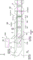
Fig. 3 is a diagram for explaining the overall flow of the manufacturing method of the absorbent body 15. The manufacturing method of the absorbent body 15 has at least the semi-finished product forming step S13, the body forming step S15, and the body cutting step S17. In the semi-finished product forming step S13, a plurality of semi-finished product absorbers 20S in which the absorbers 20 are continuous in the front-rear direction L are formed. In the body forming step S15, the semi-finished absorbent body 20S having the continuous absorbent body 20 is overlapped with the continuous sheet 30C having the continuous sheet 30, and the continuous body 15C having the continuous absorbent body 15 in the front-rear direction L is continuously formed in the conveyance direction MD. Therefore, the conveyance direction MD in the method of manufacturing the absorbent body 15 shown in fig. 3 is along the front-rear direction L of the absorbent body 15, and the orthogonal direction CD is along the width direction W of the absorbent body 15. The main body cutting step S17 is a step subsequent to the main body forming step S15, and cuts the main body continuous body 15C at the cutting position CL (the first cutting position CL1 and the second cutting position CL2) along the orthogonal direction CD orthogonal to the conveyance direction MD. The cutting position CL is a position corresponding to the front-rear direction end edge of the absorbent body 15. In this way, the respective absorbent bodies 15 are formed.
The body forming step S15 may have: a sheet conveyance step S151 of conveying a continuous sheet 30C in which the sheets 30 are continuous; and an absorber stacking step S152 of stacking the semi-finished absorber 20S on the sheet continuous body 30C. The sheet conveying step S151 can convey the leakproof sheet continuous body 32C continuous as the leakproof sheet 32 of the sheet 30, the exterior sheet continuous body 33C continuous as the exterior sheet 33 of the sheet 30, the surface sheet continuous body 31C continuous as the surface sheet 31 of the sheet 30, and the side sheet continuous body 34C continuous as the side sheet 34 of the sheet 30.
In the absorber stacking step S152, the semi-finished absorbers 20S are stacked on the sheet continuous body 30C at intervals in the front-rear direction L. The intermediate absorbent body 20S may be formed by connecting 2 absorbent bodies 20, or may be formed by connecting 3 or more absorbent bodies 20. Since the semi-finished absorbent bodies 20S in which a plurality of absorbent bodies are continuous are disposed on the sheet continuous body 30C, the plurality of absorbent bodies can be simultaneously positioned with respect to the sheet continuous body 30C. Therefore, the positioning of the absorber 20 can be simplified.
The absorber stacking step S152 may stack the semi-finished absorber 20S on the plurality of sheet continuous bodies 30C. Specifically, the semi-finished absorbent body 20S may be disposed between the leakproof sheet continuous body 32C and the topsheet continuous body 31C. In the present embodiment, the absorber stacking step S152 is performed between the second bonding step S1532 and the first bonding step S1531, which will be described later.
The joining portion forming step S153 forms the joining portion 80 joining the body constituent members 15P to each other. The joint forming step S153 will be described in detail later.
In the main body cutting step S17, the main body continuous body 15C is cut at a cutting position along the orthogonal direction CD orthogonal to the conveyance direction MD to form each absorbent main body 15. In the method for manufacturing an absorbent article, after each absorbent body 15 is obtained in the body cutting step S17, the absorbent body 15 and the outer package 50 can be joined together to obtain the absorbent article 1 as described above.
Next, a semi-finished product forming process will be described with reference to fig. 4. Fig. 4 is a diagram for explaining the flow of the semi-finished product forming step S13. The semi-finished product forming step S13 may have a core forming step S131, a core wrap covering step S132, and a continuous absorber cutting step S133. In the core forming step S131, each absorbent core 21 is formed, or a core continuum 21C in which a plurality of absorbent cores 21 are connected is formed. In the present embodiment, a core continuum 21C is formed in which 2 finished absorbent cores 21 are connected. The front end edges of the absorbent cores 21 of the core continuum 21C are connected to each other. In other forms, the rear end edges of the absorbent cores 21 of the core continuum 21C may be connected to each other. In the core forming step S131, the absorbent core 21 may be formed by laminating the absorbent material using a lamination drum not shown.
In the core cladding covering step S132, after the core cladding continuous body 22C in which the core cladding 22 is continuous is overlapped with the core continuous body 21C, the core continuous body 21C is covered with the core cladding continuous body 22C. In this way, since the core continuum 21C in which the 2 finished absorbent cores 21 are continuous is disposed on the core-clad continuum 22C, the alignment of the 2 finished absorbent cores 21 with respect to the core-clad continuum 22C can be performed simultaneously. Therefore, the positioning of the absorbent core 21 can be simplified.
In the present embodiment, the core continuous body 21C is disposed at a distance in the front-rear direction L at the center of the core layer continuous body 22C in the orthogonal direction CD. The front-rear direction L of the core continuous body 21C is along the conveyance direction MD. Then, the end portion in the orthogonal direction CD of the core-clad continuous body 22C (the portion outside the orthogonal direction CD of the core continuous body 21C) is folded along the conveyance direction MD to cover the upper surface of the absorbent core 21. This makes it possible to obtain a continuous absorber 20C in which the core continuum 21C is covered with the core-clad continuum 22C. In another manufacturing method, the core wrap covering step S132 may be configured to cover each absorbent core 21 without covering the core continuum 21C.
In the continuous absorber cutting step S133, the continuous absorber 20C is cut to form a semi-finished absorber 20S. In the continuous absorbent body cutting step S133, the continuous absorbent body 20C is cut along the orthogonal direction CD at a position corresponding to the boundary between the absorbent cores 21 (the front edges of the absorbent cores). The thus-obtained semi-finished absorbent body 20S includes 2 absorbent bodies 20, and the rear end edges of the absorbent bodies 20 are connected to each other. The edges of the semi-finished absorbent body 20S in the conveyance direction MD are aligned with the front edges of the absorbent body 20 and with the front edges of the absorbent core 21.
Fig. 5, 6, and 7 are views for explaining the joined portion forming step S153, and are views showing the joined portions (the first adhesive portion 81X, the second adhesive portion 82X, the third adhesive portion 83X, the side adhesive portion 84X, and the auxiliary joined portion 85X). Fig. 5 is a plan view of a continuous body of each sheet, and fig. 6 and 7 are cross-sectional views taken along the line shown in fig. 5. Fig. 6 is a cross-sectional view taken along a line perpendicular to the direction CD, and fig. 7 is a cross-sectional view taken along the direction MD. Specifically, fig. 7 is a sectional view taken along line 5F-5F shown in fig. 5 (d). In fig. 3, the joint portion forming step S153 is shown for convenience of explanation, but the joint portions are omitted. The first body constituting member 15P1 of the present embodiment is the front sheet 31, and the second body constituting member 15P2 is the leakage preventing sheet 32. The first body constituting member 15P1 and the second body constituting member 15P2 may be the absorbent body 20 and the sheet 30, the absorbent core 21 and the core wrap 22, the 2-layer core wrap 22 disposed with the absorbent core 21 interposed therebetween, a plurality of sheets disposed with the absorbent body 20 interposed therebetween in the thickness direction, a plurality of sheets disposed on the skin surface side of the absorbent body 20, or a plurality of sheets disposed on the non-skin surface side of the absorbent body 20. The joint portion 80 is provided in a joint region R31 of a part of the absorbent body 15 in a plan view. The absorbent body 15 may have: a joining region R31 provided with a joining portion 80 that joins the body constituting members 15P to each other; and a non-joining region R32 that does not join the body constituting members 15P to each other.
As shown in fig. 5, the joint forming step S153 may have: a first bonding step S1531 of applying an adhesive to the first body constituting member 15P1 to provide a first adhesive portion 81X; a second joining step S1532 of applying an adhesive to the second body constituting member 15P2 to provide a second adhesive portion 82X; a third joining step S1533 of applying an adhesive to a third body constituting member 15P3 other than the first body constituting member 15P1 and the second body constituting member 15P2 to provide a third adhesive portion 83X; and an auxiliary joining step S1535 of forming an auxiliary joining portion 85X joining the first body constituting member 15P1 and the second body constituting member 15P2 by any one of ultrasonic welding, thermal welding, and embossing. The order of the joining steps is not limited, and in the present embodiment, the third joining step S1533, the second joining step S1532, the first joining step S1531, and the auxiliary joining step S1535 are performed in this order. The joining portion forming step S153 may include a step of applying an adhesive to the side sheet continuous body 34C in which the side sheet is continuous to provide the side adhesive portion 84X between the first joining step S1531 and the auxiliary joining step S1535.
In the present embodiment, the length of the continuous sheet in the cross direction CD is constant for each continuous sheet conveyed in the main body forming step S15, and after the continuous sheets are stacked, the continuous sheet is cut along the shape of the leg hole opening 66. Fig. 5(d) is a plan view of the continuous body 15C in which the all-joint forming step S153 is performed. As shown in fig. 3, the continuous body 15C shown in fig. 5(d) is subjected to a body cutting step S17 after the cutting step along the shape of the leg hole opening 66 is performed.
As shown in fig. 5(a) and 6(a), the joint forming step S153 may have a third joining step S1533. In the third joining step S1533, an adhesive is applied to the third body constituting member 15P3 other than the first body constituting member 15P1 and the second body constituting member 15P2 to provide a third adhesive portion 83X. Third body constituting member 15P3 may be any body constituting member 15P other than first body constituting member 15P1 and second body constituting member 15P2, and is outer-sheet continuous body 33C in the present embodiment. Fig. 5(a) shows a state where the third adhesive portion 83X is provided on the exterior sheet continuous body 33C in the third bonding step S1533. Fig. 6(a) is a sectional view taken along line 5A-5A shown in fig. 5 (a). The 5A-5A line is a position corresponding to the first cut position CL 1.
The third adhesive portion 83X is a portion to which the adhesive is applied to the third body constituting member 15P3 in the third joining step S1533, and the third non-adhesive portion 83Y is a portion to which the adhesive is not applied to the third body constituting member 15P3 in the third joining step S1533. The third non-adhesive sections 83Y are continuous in the conveyance direction MD at both end portions of the continuous outer sheet body 33C in the orthogonal direction CD. The third adhesive section 83X continues in the conveyance direction MD at a position inside the orthogonal direction CD of the third non-adhesive section 83Y continuing in the conveyance direction MD. The third adhesive portions 83X and the third non-adhesive portions 83Y are alternately arranged in the conveyance direction MD at the center portion of the continuous outer sheet body 33C in the cross direction CD. The region where the third adhesive portions 83X are provided at intervals in the conveyance direction MD may be at least a part of the cross direction CD of the third body constituting member 15P3, or may be the entire cross direction CD of the third body constituting member 15P 3. As shown in fig. 6(a), at a position corresponding to the first cut position CL1, the third non-adhesive portion 83Y, the third adhesive portion 83X, and the third non-adhesive portion 83Y are arranged in this order from the center in the orthogonal direction CD toward the outside in the orthogonal direction.
The non-adhesive portion in the present invention includes not only a region where the adhesive is not applied but also a region where only the adhesive is applied but members are not adhered to each other via the adhesive. The adhesive portion in the present invention includes not only the area to which the adhesive is applied but also an area surrounded by the area to which the adhesive is applied (area surrounded by a spiral-coated curve). The region surrounded by the region to which the adhesive is applied may not surround the entire periphery, and may be a region surrounding at least half or more of the entire periphery.
As shown in fig. 5(b) and 6(b), the joint forming step S153 may have a second joining step S1532. In the second joining step S1532, the second body constituting member 15P2 is applied with an adhesive to provide the second adhesive portion 82X. The second body constituting member 15P2 is the other of the body constituting members 15P joined in the joining portion forming step S153, and is the leakproof sheet continuous body 32C in the present embodiment. In addition, the second body constituting member 15P2 to which the adhesive is applied in the second bonding step S1532 may be each body constituting member (1 finished body constituting member) or may be a continuous body of the body constituting member 15P. Fig. 5(b) shows a state where the second adhesive portion 82X is provided on the leakproof sheet continuous body 32C in the second bonding step S1532. Fig. 6(B) is a sectional view taken along line 5B-5B shown in fig. 5 (B). The 5B-5B line is a position corresponding to the first cut position CL 1. In fig. 5(b), the third adhesive portion 83X is omitted for convenience of explanation.
The second non-adhesive sections 82Y are continuous in the conveyance direction MD at both ends of the leakproof sheet continuous body 32C in the orthogonal direction CD. The second adhesive section 82X continues in the conveyance direction MD on the inner side in the cross direction CD than the second non-adhesive section 82Y continuing in the conveyance direction MD. The second non-adhesive section 82Y is continuous in the conveyance direction MD at the center portion of the leakproof sheet continuous body 32C in the cross direction CD. The second adhesive sections 82X and the second non-adhesive sections 82Y are alternately arranged in the conveyance direction MD between the second adhesive sections 82X and the second non-adhesive sections 82Y that are continuous in the conveyance direction MD in the direction perpendicular to the direction CD. The region where the second adhesive portions 82X are provided at intervals in the conveyance direction MD may be at least a part of the orthogonal direction CD of the second body constituting member 15P2, or may be the entire region of the orthogonal direction CD of the second body constituting member 15P 2. The length of the second non-adhesive section 82Y in the direction perpendicular to the conveyance direction MD, which is provided at intervals, may be the same as the length of the third non-adhesive section 83Y in the direction perpendicular to the CD. As shown in fig. 7, the second adhesive section 82X may overlap both ends of the third non-adhesive section 83Y in the conveyance direction MD. As shown in fig. 6(b), at a position corresponding to the first cut position CL1, the second non-adhesive portion 82Y, the second adhesive portion 82X, and the second non-adhesive portion 82Y are arranged in this order from the center in the orthogonal direction CD toward the outside in the orthogonal direction.
As shown in fig. 5(c) and 6(c), the joint forming step S153 has a first joining step S1531. In the first joining step S1531, an adhesive is applied to the first body constituting member 15P1 to provide the first adhesive portion 81X. The first body constituting member 15P1 is one of the body constituting members 15P joined in the joined portion forming step S153, and is the front sheet continuous body 31C in the present embodiment. The first body constituting member 15P1 may be each body constituting member (1 finished body constituting member) or may be a continuous body of the body constituting members. Fig. 5(C) shows a state where the first adhesive portion 81X is provided on the front sheet continuous body 31C in the first bonding step S1531. Fig. 6(C) is a sectional view taken along line 5C-5C shown in fig. 5 (C). The 5C-5C line is a position corresponding to the first cut position CL 1. In the first bonding step S1531, the first adhesive portions 81X are provided at intervals in the conveyance direction MD at least in a part of the first body constituting member 15P1 in the orthogonal direction CD. In the present embodiment, the absorber stacking step S152 is performed between the second bonding step S1532 and the first bonding step S1531, but the semifinished absorber 20S is omitted from fig. 5 (c). For convenience of explanation, the second adhesive portion 82X and the third adhesive portion 83X are omitted in fig. 5 (c).
As shown in fig. 5(d) and 6(d), the joint forming step S153 may have: a side bonding step S1534 of applying an adhesive to the side sheet continuous body 34C to provide a side adhesive portion 84X; and an auxiliary joining step S1535 of providing the auxiliary joining portion 85X. Fig. 5(d), 6(d), and 6(e) show a state where the side adhesive portion 84X and the auxiliary joining portion 85X are provided. Fig. 6(D) is a sectional view taken along the line 5D-5D shown in fig. 5 (D). The 5D-5D line is a position corresponding to the first cut position CL 1. Fig. 6(E) is a sectional view taken along the line 5E-5E shown in fig. 5 (d). The 5E-5E line is a position corresponding to the second cut position CL 2. For convenience of explanation, the first adhesive portion 81X, the second adhesive portion 82X, and the third adhesive portion 83X are omitted in fig. 5 (d).
In the first joining step S1531, the first adhesive portion 81X is provided in at least a part of the region overlapping with the semi-finished absorbent body 20S, and the first non-adhesive portion 81Y in which the first adhesive portion 81X is not provided is provided in the region not overlapping with the semi-finished absorbent body 20S. The first adhesive portion 81X is a portion to which the adhesive is applied to the first body constituting member 15P1 in the first bonding step S1531, and the first non-adhesive portion 81Y is a portion to which the adhesive is not applied to the first body constituting member 15P1 in the first bonding step S1531. The first adhesive portions 81X and the first non-adhesive portions 81Y are alternately arranged in the conveyance direction MD. As shown in fig. 7, the first adhesive portion 81X is provided over the entire area in the conveyance direction MD of the area overlapping with the semi-finished absorbent body 20S.
The method of manufacturing an absorbent article according to the present embodiment is configured to be able to suppress a load when the main continuous body 15C is cut. Specifically, the body cutting step S17 may have a first body cutting step S171 and a second body cutting step S172. As shown in fig. 3, in the first body cutting step S171, the body continuous body 15C is cut at a first cutting position CL1 in a separation region R41 where the semi-finished absorbent body 20S is separated in the front-rear direction L. The separation region R41 is a region that does not overlap with the semi-finished absorbent body 20S. The first main body cutting step S171 may be configured to cut other main body constituting members without cutting the semifinished absorbent body 20S, and in the present embodiment, only the continuous piece 30C is cut.
In the second body cutting step S172, the sheet continuous body 30C and the semi-finished absorbent body 20S are cut at the second cutting position CL2 in the lamination region R42 where the semi-finished absorbent body 20S and the sheet continuous body 30C overlap. The lamination region R42 is a region in which the semi-finished absorbent bodies 20S are arranged at least in part in the cross direction CD, and is located between the separation regions R41 in the conveyance direction MD. In addition, as long as a part of the orthogonal direction CD of the second cutting position CL2 overlaps the semi-finished absorbent body 20S, the entire region of the orthogonal direction CD of the second cutting position CL2 may not overlap the semi-finished absorbent body 20S. The first cut position CL1 may be a position corresponding to the front end edge 15F of the absorbent body 15, and the second cut position CL2 may be a position corresponding to the rear end edge 15R of the absorbent body 15.
The first cut position CL1 is provided in the separation region R41. Therefore, the first main body cutting step S171 can cut in a region where not only the absorbent core 21 but also the core clad 22 are not disposed, and the first cutting position CL1 is more easily stabilized. By providing both the first main body cutting step S171 and the second main body cutting step S172 in the main body cutting step S17, the load on the cutting blade and the load on the cutting of the peripheral members due to the force applied during cutting can be reduced as compared with the case of always cutting the continuous piece 30C and the semi-finished absorbent body 20S.
In the first joining step S1531 of the present embodiment, the first non-adhesive portion 81Y disposed between the conveyance directions MD is provided over the entire region in the orthogonal direction CD of the first body constituting member 15P1, and the first adhesive portion 81X continuous in the conveyance direction MD is not provided. The first non-adhesive portions 81Y are continuously provided in the conveyance direction MD at both ends in the orthogonal direction CD of the first body constituting member 15P1, and the first adhesive portions 81X and the first non-adhesive portions 81Y are alternately arranged in the conveyance direction MD between the first non-adhesive portions 81Y. Since the entire region in the orthogonal direction CD of the first cutting position CL1 overlaps the first non-adhesive portion 81Y, the adhesive is less likely to adhere to the cutting blade at the first cutting position, and even if the body continuous body 15C is repeatedly cut, the body continuous body 15C is easily and continuously cut. Further, since a part of the second cutting position CL2 in the cross direction CD overlaps the first non-adhesive portion 81Y, it is possible to suppress the adhesive from adhering to the cutting blade at the second cutting position, and to easily and appropriately continue cutting the main body continuous body 15C even if the main body continuous body 15C is repeatedly cut.
In a modification, in the first bonding step S1531, the first adhesive portions 81X may be provided at intervals in the conveyance direction MD at a part of the first body constituting member 15P1 in the orthogonal direction CD. That is, in the first body constituting member 15P1 of the modification, the first adhesive sections 81X that are continuous in the conveyance direction MD and the first adhesive sections 81X that are arranged at intervals in the conveyance direction MD may be provided adjacent to each other in the orthogonal direction. By not providing the first adhesive portion 81X in at least a part of the first body constituting member 15P1 in the orthogonal direction CD, the adhesive is less likely to adhere to the cutting blade, and the body continuous body 15C is easily and appropriately cut even if the body continuous body 15C is repeatedly cut, as compared with a configuration in which the first adhesive portion 81X is overlapped with the entire orthogonal direction CD of the cutting position CL.
At least a part of the first cut position CL1 and at least a part of the second cut position CL2 in the body cutting step may overlap with the non-joining region R32. The non-joined region R32 is a portion that does not overlap with the joined portion 80 (the first adhesive portion 81X, the second adhesive portion 82X, the third adhesive portion 83X, the side adhesive portion 84X, and the auxiliary joined portion 85X). The joining region R31 is a portion that overlaps at least one of the joining portions 80 (the first adhesive portion 81X, the second adhesive portion 82X, the third adhesive portion 83X, the side adhesive portion 84X, and the auxiliary joining portion 85X). As shown in fig. 6(d), at the first cutting position CL1 of the present embodiment, a non-junction region R32, a junction region R31, a non-junction region R32, a junction region R31, a non-junction region R32, a junction region R31, and a non-junction region R32 are arranged in this order from one end side toward the other end side in the orthogonal direction CD. As shown in fig. 6(e), at the second cutting position CL2 of the present embodiment, a non-joined region R32, a joined region R31, and a non-joined region R32 are arranged in this order from one end side to the other end side in the orthogonal direction CD.
Since the entire cross-direction CD perpendicular to the cutting position CL does not overlap the joint portion 80, excessive rigidity of the cut portion can be suppressed, and the load during cutting can be suppressed. In general, when the main continuous body 15C is cut, cutting is performed using a cutting device such as a cutter, and a cutting blade of the cutting device is brought into contact with the main continuous body 15C. In the case of the joint portion 80 including an adhesive such as HMA as in the first adhesive portion 81X and the second adhesive portion 82X, the adhesive is less likely to adhere to the cutting blade because the entire cutting position CL does not overlap the joint portion. Therefore, even if the cutting of the main body continuous body 15C is repeated, the cutting of the main body continuous body 15C is easily and appropriately continued.
In addition, at least a part of the first cut position CL1 and at least a part of the second cut position CL2 may overlap the engaging portion 80 that engages the body constituting members 15P with each other. Since the whole of the first cutting position and the second cutting position does not overlap the non-joined region, it is possible to suppress the rigidity of the cut portion from becoming too low, cut the cut object while applying a constant tension, cut the cut object appropriately at a desired cutting position, and suppress problems such as deviation in cutting and propagation of the cut portion to an undesired portion.
At least a part of the first cut position CL1 and at least a part of the second cut position CL2 may be disposed in a region overlapping the auxiliary joint portion 85X. In the present embodiment, a part of the first cut position CL1 in the orthogonal direction is provided in a region overlapping the auxiliary joint portion 85X. The auxiliary joining portion 85X joined by any one of ultrasonic welding, thermal welding, and embossing does not have an adhesive. Therefore, even if the auxiliary joining portion 85X is provided at the cutting position CL, the adhesive can be prevented from adhering to the cutting blade.
The bonding region R31 may be disposed on both sides of the non-bonding region R32 in the width direction W. Specifically, at the first cut position CL1, the joining region R31 is provided at a position outside the non-joining region R32 in the cross direction CD. This can suppress the body continuous body 15C from rolling up from the end portion in the cross direction CD of the body continuous body 15C when the body continuous body 15C is cut, and can stably cut the body continuous body 15C.
The first body constituting member 15P1 and the second body constituting member 15P2 may be the sheet 30 disposed with the absorbent core 21 interposed therebetween. The combination of the sheet 30 disposed with the absorbent core 21 interposed therebetween may be the topsheet 31 and the leakproof sheet 32, the topsheet 31 and the outer sheet 33, the core wrap 22 and the leakproof sheet 32 disposed on the skin surface side of the absorbent core 21, the core wrap 22 and the outer sheet 33 disposed on the skin surface side of the absorbent core 21, the core wrap 22 and the topsheet 31 disposed on the non-skin surface side of the absorbent core 21, or the core wrap 22 disposed with the absorbent core 21 interposed therebetween. According to this structure, the absorbent material that has flowed out of the absorbent core 21 can be held by the joint portions 80, and the absorbent material can be suppressed from spilling. In particular, the edges in the conveyance direction MD of the semi-finished absorbent body 20S of the present embodiment are aligned with the edges in the front-rear direction L of the absorbent core 21, and the core wrap 22 is not bonded to the positions further outward in the front-rear direction L than the edges in the front-rear direction L of the absorbent core 21. As described above, in the manufacturing method in which the plurality of absorbent cores 21 are integrally formed and the plurality of absorbers 20 are integrally formed, the entire periphery of the absorbent cores 21 in a plan view may not be covered with the core cladding 22. In this manufacturing method, the sheet 30 disposed with the absorbent core 21 interposed therebetween is preferably joined by the joining portion 80.
The joining portion 80 that joins the sheets 30 disposed with the absorbent core 21 interposed therebetween may overlap a central portion in the cross direction CD of the cutting position CL. In the present embodiment, the auxiliary joining portion 85X overlaps the center of the first cutting position CL1 in the orthogonal direction CD, and the first adhesive portion 81X and the third adhesive portion 83X overlap the center of the second cutting position CL2 in the orthogonal direction CD. The absorbent core 21 is usually disposed not over the entire region of the absorbent body 15 in the cross direction CD but in the center of the absorbent body in the cross direction CD. The absorbent core 21 contains absorbent materials such as pulp and SAP, and particularly SAP is in the form of particles and sometimes flows out from the absorbent core 21. Since the joining portion overlaps the central portion in the cross direction CD of the cutting position CL, the absorbent material can be blocked by the joining portion 80 and the absorbent material can be prevented from spilling when the absorbent material moves outward in the front-rear direction L from the absorbent core 21.
The body cutting step S17 may provide the cutting position CL in a region not overlapping the absorbent core 21. The cutting positions CL may be provided at intervals between the absorbent cores in the conveyance direction MD. The region where the absorbent core 21 is not disposed is thinner than the region where the absorbent material is not disposed and the absorbent core 21 is disposed. Therefore, the cutting position CL is easily stabilized, and the main continuous body 15C can be appropriately cut at the desired cutting position CL. In general, the absorbent core 21 is not disposed over the entire width direction W of the absorbent body 15, but is disposed in a partial region in the width direction W of the absorbent body 15. Therefore, when the absorbent core 21 is cut in a region overlapping with the absorbent core 21, the thickness varies depending on the presence or absence of the absorbent core 21 at the cut position CL. However, by providing the cutting position CL in a region not overlapping the absorbent core 21, the thickness does not change at the cutting position CL depending on the presence or absence of the absorbent core 21, the cutting position CL is stable, and the cutting can be appropriately performed at a desired cutting position CL.
The second body cutting step S172 in the body cutting step S17 may cut the sheet continuous body and the semi-finished absorbent body at the boundary of the absorbent bodies in the semi-finished absorbent body 20S with each other. In the present embodiment, the second cutting position CL2 is provided at a position corresponding to the boundary between the rear end edges of the absorbent body 20. Among the semifinished absorbers obtained by the semifinished product forming step, 2 finished absorbers were continuous. The intervals of the 2 finished absorbent cores in the semi-finished absorbent body from each other correspond to the intervals of the core continuous body 21C in the front-rear direction L in the core wrap covering step S132. In the second body cutting step S172, when the body continuous body 15C is cut at the boundary between the absorber 20 in the semi-finished absorber 20S, the body continuous body 15C can be cut in the region where the core continuous body 21C is spaced apart in the front-rear direction L. Therefore, in the second body cutting step S172, the body continuous body 15C can be cut in the region not overlapping the absorbent core 21, and the load at the time of cutting can be further suppressed.
In addition, in the body forming step S15, each of the semifinished absorbers 20S may be arranged with the first cutting position CL1 in the separation region R41 interposed therebetween. By spacing the absorbent cores 21 from each other in the semi-finished product forming step S13, and spacing the semi-finished product absorbers 20S from each other in the body forming step S15, the spacing of the absorbent cores 21 from each other on the body continuum 15C can be set. By cutting the body continuous body 15C thus configured, an absorbent body 15 having the absorbent core 21 spaced apart by a predetermined interval in the front-rear direction L can be obtained. Further, since the interval between the absorbent cores 21 in the main continuous body 15C can be set, the main continuous body 15C can be cut in a region not overlapping with the absorbent cores 21. Therefore, the cutting position is easily stabilized, and the cutting can be appropriately performed at a desired cutting position.
While the present invention has been described in detail with reference to the above embodiments, it will be apparent to those skilled in the art that the present invention is not limited to the embodiments described in the present specification. The present invention can be implemented as modifications and variations without departing from the spirit and scope of the present invention defined by the claims. Therefore, the description of the present specification is for illustrative purposes and does not have any limiting meaning to the present invention.
In the present embodiment, first body constituting member 15P1 is front sheet 31, and second body constituting member 15P2 is leakproof sheet 32. However, in other embodiments, first body constituting member 15P1 may be outer sheet 33 and second body constituting member 15P2 may be sheet 30 other than outer sheet 33, first body constituting member 15P1 may be leakage-preventing sheet 32 and second body constituting member 15P2 may be sheet 30 other than leakage-preventing sheet 32, first body constituting member 15P1 may be core wrap 22, second body constituting member 15P2 may be sheet 30 other than core wrap 22, first body constituting member 15P1 may be surface sheet 31, and second body constituting member 15P2 may be sheet 30 other than surface sheet. The adhesive portion having the adhesive for joining the body constituting members 15P to each other may be provided in a plurality of layers, and in a modification, the adhesive portion other than the first adhesive portion among the plurality of layers of adhesive portions may be provided over the entire region in the orthogonal direction of the body continuous body at the cutting position. Since at least a part of the cutting position is provided in the region overlapping the first non-adhesive portion where the first adhesive portion is not provided, an effect of easily and appropriately continuing cutting of the main body continuous body depending on the presence or absence of the first adhesive agent can be obtained.
It is noted that the entire contents of japanese patent application No. 2019-114979, which was filed on 20/6/2019, are incorporated herein by reference.
Industrial applicability
In a method for manufacturing an absorbent article in which a body continuous body in which absorbent bodies are continuous in the front-rear direction is formed and the body continuous body is cut to obtain the respective absorbent bodies, simplification of positioning of an absorbent body and suppression of a load at the time of cutting can be both achieved.
Description of reference numerals
1: absorbent article, 15: absorbent body, 15C: body continuum, 15P: body constituent member, 20: absorber, 20C: continuous absorbent, 20S: semi-finished product absorber, 21: absorbent core, 21C: core continuum, 22: core-cladding layer, 22C: core-cladding continuum, 30: sheet, 30C: sheet continuous body, 31: surface sheet, 31C: surface sheet continuous body, 32: leak-proof sheet, 32C: leakproof sheet continuous body, 33: leak-proof sheet, 33C: leakproof sheet continuous body, 50: exterior body, 51: front side exterior body, 52: rear-side outer body, 60: side joint, 80: joint, 81X: first adhesive portion, 81Y: first non-adhesive portion, 82X: second adhesive portion, 82Y: second non-adhesive portion, 83X: third adhesive portion, 83Y: third non-adhesive portion, 85X: auxiliary joint, CL: cutting position, CL 1: first cut position, CL 2: second cutting position, S13: semi-finished product forming step, S131: core forming step, S132: core-clad layer covering step, S133: continuous absorbent body cutting step, S15: body forming step, S151: sheet conveyance step, S152: absorber stacking step, S153: joint portion forming step, S1531: first bonding step, S1532: second bonding step, S1533: third joining step, S1535: auxiliary engagement step, S17: main body cutting step, S171: first body cutting step, S172: second body cutting step, R31: junction region, R32: non-junction region, R41: separation region, R42: laminated region, S1: front waistline region, S2: rear waist region, S3: crotch region, L: front-back direction, CD: orthogonal direction, MD: conveying direction, W: the width direction.
Claims (7)
1. A method for manufacturing an absorbent article having an absorbent body composed of a plurality of body constituting members, the plurality of body constituting members including: an absorbent body including an absorbent core and having a front-back direction and a width direction orthogonal to the front-back direction; and a sheet overlapping with the absorbent body,
it is characterized in that the preparation method is characterized in that,
the method for manufacturing the absorbent article comprises the following steps:
a semi-finished product forming step of forming a plurality of semi-finished product absorbers in which the absorbers are continuous in the front-rear direction;
a body forming step of forming a body continuum in which the absorbent bodies are continuous in the front-rear direction by overlapping the semi-finished absorbent bodies with respect to a sheet continuum in which the sheet is continuous in the front-rear direction at intervals in the front-rear direction; and
a body cutting step of cutting the body continuous body at a cutting position along the width direction to form each of the absorbent bodies,
the body cutting step includes: a first body cutting step of cutting the continuous sheet body at a first cutting position in a separation region where the semi-finished absorbent body is separated in the front-rear direction; and a second body cutting step of cutting the continuous sheet body and the semi-finished product absorber at a second cutting position in a lamination region where the semi-finished product absorber and the continuous sheet body overlap.
2. The method of manufacturing an absorbent article according to claim 1,
at least a part of the first cutting position and at least a part of the second cutting position overlap a non-joining region where the body constituent members are not joined to each other.
3. The method of manufacturing an absorbent article according to claim 1 or 2,
at least a part of the first cutting position and at least a part of the second cutting position overlap with a joining region provided with a joining portion that joins the body constituent members to each other.
4. The method of manufacturing an absorbent article according to claim 3,
the joining regions are disposed on both sides in the width direction of a non-joining region where the body constituent members are not joined to each other.
5. The method for manufacturing an absorbent article according to any one of claims 1 to 3,
at least a portion of the first cut location and at least a portion of the second cut location are disposed in a region that does not overlap the absorbent core.
6. The method for manufacturing an absorbent article according to any one of claims 1 to 5,
the semi-finished product forming step includes:
a core forming step of forming a core continuum in which the front end edges of the absorbent cores are adjacent to each other or the rear end edges of the absorbent cores are adjacent to each other, and 2 finished products of the absorbent cores are continuous;
an absorber forming step of forming a continuous absorber in which the absorber is continuous by overlapping a continuous core body with a continuous cladding layer covering the absorbent core in the front-rear direction at intervals in the front-rear direction; and
an absorbent cutting step of cutting the continuous absorbent body along the width direction at a boundary between the absorbent cores in the core continuum, forming the semi-finished absorbent body in which the absorbent bodies of 2 finished products are continuous in the front-rear direction,
in the second body cutting step, the sheet continuous body and the semi-finished absorbent body are cut at a boundary of the absorbent bodies with each other in the semi-finished absorbent body.
7. The method of manufacturing an absorbent article according to claim 6,
in the body forming step, each of the semifinished absorbers is disposed with the first cutting position in the separation region interposed therebetween.
Applications Claiming Priority (3)
| Application Number | Priority Date | Filing Date | Title |
|---|---|---|---|
| JP2019114979A JP6825045B2 (en) | 2019-06-20 | 2019-06-20 | Manufacturing method of absorbent articles |
| JP2019-114979 | 2019-06-20 | ||
| PCT/JP2020/023724 WO2020256003A1 (en) | 2019-06-20 | 2020-06-17 | Method for manufacturing absorbent article |
Publications (1)
| Publication Number | Publication Date |
|---|---|
| CN114040735A true CN114040735A (en) | 2022-02-11 |
Family
ID=73994513
Family Applications (1)
| Application Number | Title | Priority Date | Filing Date |
|---|---|---|---|
| CN202080044491.3A Pending CN114040735A (en) | 2019-06-20 | 2020-06-17 | Method for manufacturing absorbent article |
Country Status (3)
| Country | Link |
|---|---|
| JP (1) | JP6825045B2 (en) |
| CN (1) | CN114040735A (en) |
| WO (1) | WO2020256003A1 (en) |
Citations (7)
| Publication number | Priority date | Publication date | Assignee | Title |
|---|---|---|---|---|
| JPS5813701A (en) * | 1981-07-20 | 1983-01-26 | ユニ・チヤ−ム株式会社 | Production of disposable diaper |
| CN101849874A (en) * | 2009-09-18 | 2010-10-06 | 尤妮佳股份有限公司 | Absorbent article manufacturing method and manufacturing device |
| CN104203174A (en) * | 2012-05-10 | 2014-12-10 | 株式会社瑞光 | Method for producing disposable wearable article |
| CN104349754A (en) * | 2012-05-31 | 2015-02-11 | 尤妮佳股份有限公司 | Absorbent article manufacturing device and absorbent article manufacturing method |
| CN107456319A (en) * | 2017-09-12 | 2017-12-12 | 黄山富田精工制造有限公司 | A kind of manufacture method of absorbent commodity |
| CN108697540A (en) * | 2016-03-28 | 2018-10-23 | 金伯利-克拉克环球有限公司 | Method for applying elastic strands |
| CN109077853A (en) * | 2017-06-13 | 2018-12-25 | 法麦凯尼柯数据股份公司 | Device and method for producing the Elastic composite band with intermittent elastic part |
Family Cites Families (1)
| Publication number | Priority date | Publication date | Assignee | Title |
|---|---|---|---|---|
| JP2577095B2 (en) * | 1989-09-22 | 1997-01-29 | ユニ・チャーム株式会社 | Manufacturing method of disposable wearing article |
-
2019
- 2019-06-20 JP JP2019114979A patent/JP6825045B2/en active Active
-
2020
- 2020-06-17 CN CN202080044491.3A patent/CN114040735A/en active Pending
- 2020-06-17 WO PCT/JP2020/023724 patent/WO2020256003A1/en not_active Ceased
Patent Citations (7)
| Publication number | Priority date | Publication date | Assignee | Title |
|---|---|---|---|---|
| JPS5813701A (en) * | 1981-07-20 | 1983-01-26 | ユニ・チヤ−ム株式会社 | Production of disposable diaper |
| CN101849874A (en) * | 2009-09-18 | 2010-10-06 | 尤妮佳股份有限公司 | Absorbent article manufacturing method and manufacturing device |
| CN104203174A (en) * | 2012-05-10 | 2014-12-10 | 株式会社瑞光 | Method for producing disposable wearable article |
| CN104349754A (en) * | 2012-05-31 | 2015-02-11 | 尤妮佳股份有限公司 | Absorbent article manufacturing device and absorbent article manufacturing method |
| CN108697540A (en) * | 2016-03-28 | 2018-10-23 | 金伯利-克拉克环球有限公司 | Method for applying elastic strands |
| CN109077853A (en) * | 2017-06-13 | 2018-12-25 | 法麦凯尼柯数据股份公司 | Device and method for producing the Elastic composite band with intermittent elastic part |
| CN107456319A (en) * | 2017-09-12 | 2017-12-12 | 黄山富田精工制造有限公司 | A kind of manufacture method of absorbent commodity |
Also Published As
| Publication number | Publication date |
|---|---|
| JP2021000223A (en) | 2021-01-07 |
| JP6825045B2 (en) | 2021-02-03 |
| WO2020256003A1 (en) | 2020-12-24 |
Similar Documents
| Publication | Publication Date | Title |
|---|---|---|
| TW568777B (en) | Pants-type disposable wearing article | |
| US9084698B2 (en) | Absorbent article with folded liquid-absorbent structure | |
| US10098795B2 (en) | Absorbent article | |
| JP5250407B2 (en) | Disposable pants-type diaper and method for manufacturing the same | |
| CN101803975A (en) | Manufacturing method of disposable wearing article | |
| CN114025724B (en) | Method for manufacturing absorbent article | |
| WO2014178305A1 (en) | Absorbent article production method and absorbent article | |
| CN106102673A (en) | Absorbent commodity manufacture method | |
| CN101578082B (en) | Method for producing disposable underpants type diaper | |
| KR102419798B1 (en) | Absorbent article and method for manufacturing pant-type absorbent article | |
| CN114040735A (en) | Method for manufacturing absorbent article | |
| CN111511323B (en) | Absorbent article | |
| CN103189028B (en) | Production method for disposable item of clothing | |
| CN114845672B (en) | Method for manufacturing urine absorption pad | |
| CN111511324B (en) | Absorbent article | |
| JP7100977B2 (en) | Absorbent article | |
| CN105208985A (en) | Absorbent article with wings and manufacturing method therefor | |
| KR101847797B1 (en) | Absorbent article | |
| WO2020116591A1 (en) | Disposable diaper | |
| JP7149070B2 (en) | absorbent article | |
| JP7145756B2 (en) | absorbent article | |
| WO2024219426A1 (en) | Wearable article manufacturing method | |
| JP6567640B2 (en) | Absorbent articles | |
| JP2007296257A (en) | Method for manufacturing worn article |
Legal Events
| Date | Code | Title | Description |
|---|---|---|---|
| PB01 | Publication | ||
| PB01 | Publication | ||
| SE01 | Entry into force of request for substantive examination | ||
| SE01 | Entry into force of request for substantive examination | ||
| AD01 | Patent right deemed abandoned |
Effective date of abandoning: 20230331 |
|
| AD01 | Patent right deemed abandoned |