The priority and benefit of U.S. provisional patent application serial No. 62/842,178, entitled "orthoppedic IMPLANT SYSTEM WITH BONE connecting feeds," filed on 2/5 in 2019, which is expressly incorporated herein by reference in its entirety.
Disclosure of Invention
According to one aspect of the present disclosure, a unicompartmental tibial insert includes an anterior end, a posterior end, an articular surface extending from the anterior end to the posterior end, and a bottom surface opposite the articular surface and extending from the anterior end to the posterior end. The articular surface is configured to articulate with a corresponding condyle of a natural or prosthetic femur. The bottom surface is configured to couple with a unicompartmental tibial tray and is non-planar.
In some embodiments, the articular surface has a concave shape when viewed in the sagittal plane, and the bottom surface has a convex shape when viewed in the sagittal plane. Additionally or alternatively, the articular surface may have a concave shape when viewed in the coronal plane and the bottom surface may have a convex shape when viewed in the coronal plane.
The perpendicular distance between the articular surface and the bottom surface may define the thickness of the tibial insert. In some embodiments, the thickness of the tibial insert is constant between the anterior end and the posterior end. For example, the thickness of the tibial insert is about six millimeters. Further, in some embodiments, wherein the curvature of the articular surface matches the curvature of the bottom surface.
According to another aspect of the present disclosure, a unicompartmental tibial insert includes an anterior end, a posterior end, an articular surface extending from the anterior end to the posterior end, and a bottom surface opposite the articular surface and extending from the anterior end to the posterior end. The articular surface is configured to articulate with a corresponding condyle of a natural or prosthetic femur. The bottom surface is configured to couple with a unicompartmental tibial tray and is non-planar. The perpendicular distance between the articular surface and the bottom surface may define a thickness of the tibial insert that is constant between the anterior end and the posterior end.
According to further aspects of the present disclosure, a unicompartmental tibial insert may include an anterior end, a posterior end, an articular surface extending from the anterior end to the posterior end, and a bottom surface opposite the articular surface and extending from the anterior end to the posterior end. The articular surface is configured to articulate with a corresponding condyle of a natural or prosthetic femur. The bottom surface is configured to couple with a single compartment tibial tray and includes a planar base surface and a tab extending from the planar base surface. The protrusion has a curved outer surface.
In some embodiments, the articular surface can have a concave shape when viewed in the sagittal plane, and the protrusion of the bottom surface can have a convex shape when viewed in the sagittal plane. Additionally or alternatively, the articular surface may have a concave shape when viewed in the coronal plane and the protrusion of the bottom surface may have a convex shape when viewed in the coronal plane.
The perpendicular distance between the articular surface and the bottom surface may define the thickness of the tibial insert. In such embodiments, the thickness of the tibial insert may be constant between the anterior end and the posterior end. For example, the thickness of the tibial insert is about six millimeters.
In some embodiments, a first perpendicular distance between the articular surface and the planar base surface of the bottom surface defines a first thickness, and a second perpendicular distance between the articular surface and the curved outer surface of the protrusion defines a second perpendicular distance. The second vertical distance may be equal to the first vertical distance.
Additionally, in some embodiments, the perpendicular distance between the articular surface and the curved outer surface of the protrusion of the bottom surface can define the thickness of the protrusion. In some embodiments, the thickness of the protrusion may be constant. For example, the thickness of the protrusion may be about six millimeters. Additionally, in some embodiments, the shape of the protrusion of the bottom surface may be semi-elliptical. Additionally, in some embodiments, the projection of the bottom surface is offset toward the posterior end of the tibial insert from the medial to lateral axis of the tibial insert.
According to yet another aspect of the present disclosure, a tibial knee prosthesis may include an anterior side, a posterior side, a medial articular surface, a lateral articular surface, and a bottom surface, wherein the medial articular surface extends from the anterior side to the posterior side, the lateral articular surface extends from the anterior side to the posterior side, and the bottom surface is opposite the medial articular surface and the lateral articular surface and extends from the anterior side to the posterior side. The medial articular surface may be configured to articulate with the medial condyle of a natural or prosthetic femur. Similarly, the lateral articular surface may be configured to articulate with the lateral condyle of a natural or prosthetic femur. The bottom surface includes a planar base surface and a protrusion extending from the planar base surface below the medial articular surface or the lateral surface. The protrusion may have a curved outer surface.
In some embodiments, the tibial insert may further comprise a peg extending from a projection of the bottom surface. Additionally, in some embodiments, each of the medial and lateral articular surfaces can have a concave shape when viewed in the sagittal plane. In such embodiments, the protrusion of the bottom surface may have a convex shape when viewed in the sagittal plane.
In some embodiments, the perpendicular distance between the medial articular surface and the curved outer surface of the projection or between the lateral articular surface and the curved outer surface of the projection defines the thickness of the projection. In such embodiments, the thickness of the protrusion may be constant and about six millimeters.
In some embodiments, the tibial insert may be embodied as a single-piece prosthesis and include a polymeric bearing attached to a metal platform. In such embodiments, the polymeric bearing comprises a medial articular surface and a lateral articular surface, and the metal platform comprises a bottom surface having a planar base surface and a protrusion extending from the planar base surface to below the medial articular surface or the lateral articular surface.
Drawings
The detailed description refers specifically to the accompanying drawings in which:
FIG. 1 is an exploded perspective view of an embodiment of a typical orthopaedic knee prosthesis system for implantation in a patient's tibia;
FIG. 2 is a perspective view of the tibia of FIG. 1 after resection of the total knee prosthesis;
FIG. 3 is a perspective view of the tibia of FIG. 2 after resection of the unicompartmental knee prosthesis;
FIG. 4 is a medial to lateral cross-sectional view of a typical tibial insert that may form a component of the typical orthopaedic knee prosthesis system of FIG. 1;
FIG. 5 is an upper perspective view of an embodiment of a unicompartmental tibial insert having bone protection features;
FIG. 6 is a top plan view of the unicompartmental tibial insert of FIG. 5;
FIG. 7 is a lower plan view of the unicompartmental tibial insert of FIG. 5;
FIG. 8 is a medial elevational view of the unicompartmental tibial insert of FIG. 5;
FIG. 9 is a rear elevational view of the unicompartmental tibial insert of FIG. 5;
FIG. 10 is an anterior to posterior cross-sectional view of the unicompartmental tibial insert of FIG. 5;
FIG. 11 is an anterior to posterior cross-sectional view of the exemplary tibial insert similar to FIG. 4;
FIG. 12 is a medial to lateral cross-sectional view of the unicompartmental tibial insert of FIG. 5;
FIG. 13 is a medial to lateral cross-sectional view of the exemplary tibial insert of FIG. 11;
FIG. 14 is a perspective view of the tibia of the patient prepared to implant the unicompartmental tibial insert of FIG. 5 after resection of the unicompartmental tibial insert;
FIG. 15 is a cross-sectional evaluation of the tibia of the patient of FIG. 14 after implantation of a unicompartmental knee prosthesis including the unicompartmental tibial insert of FIG. 5;
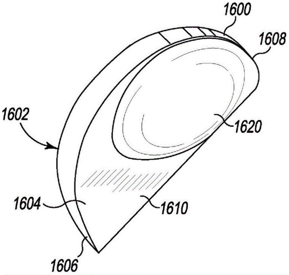
FIG. 16 is a lower perspective view of another embodiment of a unicompartmental tibial insert having a bone protection feature;
FIG. 17 is a top plan view of the unicompartmental tibial insert of FIG. 16;
FIG. 18 is a lower plan view of the unicompartmental tibial insert of FIG. 16;
FIG. 19 is a medial elevational view of the unicompartmental tibial insert of FIG. 16;
FIG. 20 is a rear elevational view of the unicompartmental tibial insert of FIG. 16;
FIG. 21 is an anterior to posterior cross-sectional view of the unicompartmental tibial insert of FIG. 16;
FIG. 22 is an anterior to posterior cross-sectional view of the exemplary tibial insert similar to FIG. 10;
FIG. 23 is a medial to lateral cross-sectional view of the unicompartmental tibial insert of FIG. 16;
FIG. 24 is a medial to lateral cross-sectional view of the exemplary tibial insert of FIG. 22;
FIG. 25 is a lower perspective view of a tibial total knee prosthesis having a bone protection feature;
FIG. 26 is a lower plan view of the tibial total knee prosthesis of FIG. 25;
FIG. 27 is a top plan view of the tibial total knee prosthesis of FIG. 25;
FIG. 28 is a rear elevational view of the tibial total knee prosthesis of FIG. 25;
FIG. 29 is an anterior elevational view of the tibial total knee prosthesis of FIG. 25;
FIG. 30 is a side elevational view of the tibial total knee prosthesis of FIG. 25; and is
Fig. 31 is another side elevational view of the tibial total knee prosthesis of fig. 25.
Detailed Description
While the concepts of the present disclosure are susceptible to various modifications and alternative forms, specific exemplary embodiments thereof have been shown by way of example in the drawings and will herein be described in detail. It should be understood, however, that there is no intention to limit the concepts of the disclosure to the specific forms disclosed, but on the contrary, the intention is to cover all modifications, equivalents, and alternatives falling within the spirit and scope of the invention as defined by the appended claims.
Throughout the specification, when referring to orthopaedic implants and surgical instruments described herein and the natural anatomy of a patient, terms denoting anatomical reference, such as anterior, posterior, medial, lateral, superior, inferior, and the like, may be used. These terms have well-known meanings in both the anatomical studies and orthopedic fields. Unless otherwise indicated, these anatomical reference terms used in the written detailed description and claims are intended to be consistent with their well-known meaning.
Referring now to fig. 1, an exemplary orthopaedic total knee prosthesis system 100 includes a typical "living" or "rotating" orthopaedic knee prosthesis 102 and a typical "fixed" orthopaedic knee prosthesis 104. Each of the orthopaedic knee prosthesis 102 and the orthopaedic knee prosthesis 104 is configured to be secured to a surgically-prepared proximal end of a patient's tibia 106, as discussed in more detail below.
The exemplary "living" orthopaedic knee prosthesis 102 includes a tibial insert 110 and a tibial tray 112. The tibial insert 110 is typically formed from a polymeric material such as Ultra High Molecular Weight Polyethylene (UHMWPE), while the tibial tray 112 is formed from a metallic material such as cobalt chromium or titanium.
The tibial insert 110 is configured to couple with a tibial tray 112 and includes a platform 120 having an upper bearing surface 122 and a bottom surface 124. To facilitate coupling of the tibial insert 110 and the tibial tray 112, the tibial insert 110 also includes a shaft 126 extending downwardly from the bottom surface 124 of the platform 120. The shaft 126 is configured to be received in the bore 138 of the tibial tray 112. In use, the tibial insert 110 is configured to rotate relative to the tibial tray 112 about an axis defined by the shaft 126.
As described below in connection with fig. 2, the tibial tray 112 is configured to be secured to a surgically-prepared proximal end of the patient's tibia 106. The tibial tray 112 may be secured to the patient's tibia via the use of bone cement or other attachment means. The tibial tray 112 includes a platform 130 having a top surface 132 and a bottom surface 134. The tibial tray 112 also includes a stem 136 extending downwardly from the bottom surface 134 of the platform 130. An aperture 138 is defined in the top surface 132 of the platform 130 and extends downwardly into the shaft 126.
The exemplary "fixed" orthopaedic knee prosthesis 104 includes a tibial insert or bearing 140 attached to a tibial plateau or base 142. The tibial insert 140 is typically formed from a polymeric material, such as ultra-high molecular weight polyethylene (UHMWPE), while the tibial plateau 142 is formed from a metallic material, such as cobalt chromium or titanium. The orthopaedic knee prosthesis 104 may also include one or more pegs or keels 150 extending downward from a bottom surface 152 of the tibial plateau 142 to facilitate fixation to the patient's tibia 106.
The tibial insert 140 and the tibial plateau 142 may be of modular design (e.g., the tibial insert 140 and the tibial plateau 142 may be separate components) or of unitary design. For example, in some embodiments, the tibial insert 140 may be permanently attached (e.g., molded) to the tibial plateau 142. Regardless, similar to the tibial tray 112, the tibial platform 142 is configured to be secured to a surgically-prepared proximal end of the patient's tibia 106.
As described above, either of the orthopaedic knee prosthesis 102 or the orthopaedic knee prosthesis 104 may be used for Total Knee Arthroplasty (TKA) to replace the proximal end of the patient's tibia 106. To do so, the patient's tibia 106 is resected via a planar cut across the tibial plateau to create a planar resected surface 200 at the proximal end of the patient's tibia 106, as shown in fig. 2. The planar resected surface 200 provides a base on which the bottom surface 134 of the platform 130 of the tibial tray 112 or the bottom surface 152 of the tibial platform 142 bears, depending on which orthopaedic knee prosthesis 102, 104 is used. In either case, the tibial inserts 110, 140 provide an artificial tibial articular surface on which a patient's natural or prosthetic femur can articulate. Of course, additional surgery (e.g., drilling of the tibia 106) may be required to fully implant the orthopaedic knee prostheses 102, 104.
In some cases, total knee arthroplasty may not be necessary because only one condyle of the patient's tibia and/or femur may be diseased or damaged. In such cases, the orthopaedic unicompartmental knee prosthesis may be used to replace the natural condyles of the patient's tibia 106 and/or femur. A typical unicompartmental knee prosthesis is similar to one half of a total knee prosthesis, but is configured to replace a single condyle or facet. Thus, a typical unicompartmental tibial prosthesis includes a tibial insert having a single articular surface and a tibial tray configured to be secured to the patient's tibia 106. Unicompartmental Knee Arthroplasty (UKA) surgery may be used to implant a typical unicompartmental tibial prosthesis. To do so, one of the articular surfaces of the patient's tibia 106 is resected via a planar cut across the tibial plateau to create a planar resected surface 300 on the medial or lateral side at the proximal end of the patient's tibia 106, as shown in fig. 3. Similar to the planar resected surface 200 discussed above with respect to fig. 2, the planar resected surface 300 provides a base on which the bottom surface of the platform of a typical unicompartmental tibial prosthesis is supported. Of course, if a bicompartmental knee prosthesis is used, both the medial and lateral sides of the proximal end of the patient's tibia 106 may be resected.
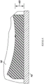
One criterion that is generally recommended and observed in orthopaedic tibial prostheses is a minimum distance between the articular surface of the tibial insert and the top surface of the tibial tray. As mentioned above, the tibial insert is typically formed of a polymeric material, while the tibial tray is metal. Therefore, a minimum thickness of the polymeric tibial insert should be maintained to ensure that the tibial insert does not crack or excessively wear during use. For example, as shown in fig. 4, a minimum distance 400 (i.e., the thickness of the tibial insert) of six to eight millimeters between the articular surface of the tibial insert 140 and the top surface of the tibial plateau 142 may be observed. However, maintaining a minimum tibial insert thickness, particularly at the point of dwell of the articular surface of the tibial insert, may result in the need to remove excess bone from the patient's tibia. That is, due to the curvature of the articular surface of a typical tibial insert, the patient's tibia 106 must be resected a distance equal to a minimum distance (e.g., 6 mm to 8 mm) beyond the dwell point of the articular surface, which can result in the resection of excess bone in those areas anterior and posterior to the dwell point of the articular surface where the articular surface is not as deep as the dwell point.
Additionally, in some cases, a planar resection of the patient's tibia 106 may result in a "teeter-totter" loading effect of the tibial knee prosthesis, wherein a compressive load on one side of the tibial knee prosthesis may result in lifting of the opposite side. In addition, flexion and extension of the artificial knee joint can transmit shear forces across the articular surfaces of the orthopaedic prosthesis of the artificial knee joint. Because the planar surface has reduced resistance to shear forces, pegs or keels may be required on the orthopaedic tibial prosthesis to resist such shear forces that require additional bone removal.
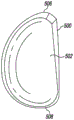
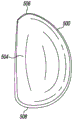
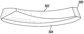
Referring now to fig. 5-9, the example unicompartmental tibial insert 500 includes bone protection features to reduce the amount of bone removed during implantation of the tibial insert 500 into the tibia of a patient. When viewed in plan as shown in fig. 6 and 7, the unicompartmental tibial insert 500 is generally "D-shaped" and includes an articular surface 502 and a bottom surface 504 opposite the articular surface 502. The articular surface 502 extending from the anterior end 506 to the posterior end 508 of the tibial insert 500 is curved and is configured to articulate with a corresponding natural or prosthetic condyle of the patient's femur. In addition, unlike typical unicompartmental tibial inserts, the bottom surface 504 is also curved and extends from the anterior end 506 to the posterior end 508 of the tibial insert 500.
Illustratively, the articular surface 502 has a concave curvature and the bottom surface 504 has a convex curvature such that the bottom surface 504 mirrors the curvature of the articular surface 502. For example, as shown in fig. 8, the articular surface 502 is concave in the anterior-posterior direction when viewed in the sagittal plane, and the bottom surface 504 is convex in the anterior-posterior direction when viewed in the sagittal plane. Similarly, as shown in fig. 9, the articular surface 502 is concave in the medial-lateral direction when viewed in the coronal plane, and the bottom surface 504 is convex in the medial-lateral direction when viewed in the coronal plane.
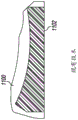
Referring now to fig. 10-13, in some embodiments, the curvature of the bottom surface 504 matches the curvature of the articular surface 502 such that the thickness of the unicompartmental tibial insert 500 is constant within manufacturing tolerances. For example, in the exemplary embodiment, the perpendicular distance 1000 defined between the articular surface 502 and the bottom surface 504 defines a thickness of the unicompartmental tibial insert 500 that is constant in the anterior-posterior direction as shown in fig. 10 and the medial-lateral direction as shown in fig. 12.
As shown in fig. 10 and 12, the perpendicular distance 1000 is defined by the length of an imaginary line (distance 1000) that is perpendicular to an imaginary tangent 503 to the articular surface 502 and perpendicular to an imaginary tangent 505 to the bottom surface 504. For example, the perpendicular distance 1000 may be measured as the distance between the contact point of the imaginary tangent line 503 with the articular surface 502 and the contact point of the imaginary tangent line 505 with the bottom surface 504.
In contrast, as shown in fig. 11 and 12, the exemplary unicompartmental tibial insert 1100 has a flat bottom surface 1102, which causes the thickness of the exemplary unicompartmental tibial insert 1100 to vary in both the anterior-posterior direction as shown in fig. 11 and the medial-lateral direction as shown in fig. 13. Thus, a typical unicompartmental tibial insert 1100 requires removal of additional bone of the patient's tibia in the peripheral anterior, posterior, medial, and lateral regions (i.e., regions away from the dwell point).
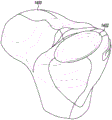
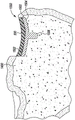
Referring now to fig. 14 and 15, it should be understood that the unicompartmental tibial insert 500 may include or otherwise be configured to mate with a unicompartmental tibial tray 1500 to form a unicompartmental tibial prosthesis 1550. In some embodiments, the unicompartmental tibial tray 1500 may include a tibial plateau 1502 having a curved top surface 1504 formed to couple with the unicompartmental tibial insert 500 and a bottom surface 1506 that is curved similar to the bottom surface 504 of the unicompartmental tibial insert 500 or otherwise matches the curvature of the bottom surface of the unicompartmental tibial insert to reduce the amount of bone removed during implantation. Thus, as shown in fig. 14, the unicompartmental tibial prosthesis 1550 may be implanted into a circular or semi-elliptical recess 1402 drilled or otherwise formed in the proximal end of the patient's tibia 1400 without the need for a planar cut into the patient's tibia 1400 as shown. Due to the curved bottom surfaces 504, 1506, the recess 1402 can be formed to have a minimum depth required to ensure a minimum distance between the articular surface 502 of the unicompartmental tibial insert 500 and the top surface 1504 of the tibial tray 1500. In this way, the planar resection of the bone of the patient's tibia 1400 relative to the patient's tibia is preserved. Additionally, it should be appreciated that the elliptical shape of the recess 1402 may provide improved shear resistance, which may reduce or eliminate the need for pegs or keels on the tibial tray 1500 and further protect the bone of the patient's tibia 1400.
Referring now to fig. 16-20, another example unicompartmental tibial insert 1600 includes bone protection features to reduce the amount of bone removed during implantation of the tibial insert 1600 into the tibia of a patient. The unicompartmental tibial insert 1600 is similar to the unicompartmental tibial insert 500 described above, and is generally "D-shaped" when viewed in plan view as shown in fig. 17 and 18. Unicompartmental tibial insert 1600 includes an articular surface 1602 and a bottom surface 1604 opposite articular surface 1602. Similar to the unicompartmental tibial insert 500, the articular surface 1602 extending from the anterior end 1606 to the posterior end 1608 of the tibial insert 1600 is curved and is configured to articulate with a corresponding natural or prosthetic condyle of the patient's femur. However, bottom surface 1604 of unicompartmental tibial insert 1600 has a planar base surface 1610 and a protrusion 1620 extending away (e.g., downward) from planar base surface 1610.
The protrusion 1620 has a curved outer surface with a convex curvature that mirrors the concave curvature of the articular surface 1602 in the region of the protrusion 1620. For example, as shown in fig. 19, the articular surface 1602 is concave in the anterior-posterior direction when viewed in the sagittal plane, and the curved outer surface of the protrusion 1620 is convex in the anterior-posterior direction when viewed in the sagittal plane. Similarly, as shown in fig. 20, the articular surface 1602 is concave in the medial-lateral direction when viewed in the coronal plane, and the curved outer surface of the protrusion 1620 is convex in the medial-lateral direction when viewed in the coronal plane.
The protrusion 1620 is illustratively semi-elliptical in shape, but may have a different shape in other embodiments. The protrusion 1620 is located on the planar base surface 1610 so as to align with the dwell point of the articular surface 1602 such that the thickness of the unicompartmental tibial insert 1600 meets a minimum thickness (e.g., 6 mm to 8 mm). For example, as shown in fig. 18, because the dwell point of the articular surface 1602 is located toward the posterior end 1608 of the unicompartmental tibial insert 1600, the projection 1620 is also offset toward the posterior end 1608 relative to the medial-lateral axis 1630 of the unicompartmental tibial insert 1600.
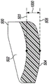
Referring now to fig. 21-24, in some embodiments, the curvature of the curved outer surface of protrusion 1620 matches the curvature of articular surface 1602 such that the thickness of unicompartmental tibial insert 1600 in the region of protrusion 1620 is constant within manufacturing tolerances. For example, in an exemplary embodiment, the perpendicular distance 2100 between the articular surface 1602 and the curved outer surface of the protrusion 1620 defines the thickness of the protrusion 1620, which is constant in the anterior-posterior direction as shown in fig. 21 and the medial-lateral direction as shown in fig. 23.
As shown in fig. 21 and 23, the perpendicular distance 2100 is defined by the length of an imaginary line (distance 2100) that is perpendicular to an imaginary tangent 1603 tangent to the articular surface 1602 and perpendicular to an imaginary tangent 1605 tangent to the curved outer surface of the protrusion 1620. For example, the perpendicular distance 2100 may be measured as the distance between the point of contact of the imaginary tangent line 1603 with the articular surface 1602 and the point of contact of the imaginary tangent line 1604 with the curved outer surface of the protrusion 1620.
In contrast, as shown in fig. 22 and 24, the exemplary unicompartmental tibial insert 1100 has a flat bottom surface 1102, which causes the thickness of the exemplary unicompartmental tibial insert 1100 to vary in both the anterior-posterior direction as shown in fig. 22 and the medial-lateral direction as shown in fig. 24.
Illustratively, the overall thickness of the unicompartmental tibial insert 1600 varies between the protrusion 1620 and the planar base surface 1610. For example, as shown in fig. 21, the perpendicular distance 2102 between the articular surface 1602 and the planar base surface 1610 defines a thickness of the unicompartmental tibial insert 1600 that is different than the thickness of the protrusion 1620 described above. However, in embodiments, the overall thickness of the unicompartmental tibial insert 1600 may not be very thick, and may be equal to the thickness of the protrusion 1620 (i.e., the vertical distance 2100).
The tibial inserts 500, 1600 have been shown and described as unicompartmental tibial inserts for replacing a single condyle of a patient's tibia. However, it should be understood that in some embodiments, the medial unicompartmental tibial insert 500 and the lateral unicompartmental tibial insert 1600 may be used to form a bicompartmental tibial insert to replace both condyles of a patient's tibia.
Referring now to fig. 25-31, exemplary tibial knee prosthesis 2500 includes bone protection features to reduce the amount of bone removed during implantation of the tibial knee prosthesis 2500 in a patient's tibia. Tibial knee prosthesis 2500 is embodied as a total knee prosthesis configured to replace a proximal end of a patient's tibia. As such, tibial knee prosthesis 2500 includes medial articular surface 2502, lateral articular surface 2522, and bottom surface 2504 opposite medial articular surface 2502 and lateral articular surface 2522. The medial articular surface 2502, which extends from the anterior end 2506 to the posterior end 2508 of the tibial knee prosthesis 2500, is curved and is configured to articulate with a corresponding natural or prosthetic medial condyle of the patient's femur. Similarly, a lateral articular surface 2522 extending from an anterior end 2506 to a posterior end 2508 of tibial knee prosthesis 2500 is curved and is configured to articulate with a corresponding natural or prosthetic lateral condyle of the patient's femur. However, bottom surface 2504 has a planar base surface 2510 and a pair of projections 2550, 2552 extending away (e.g., downward) from planar base surface 2510.
Each of the projections 2550, 2552 of the tibial knee prosthesis 2500 can be substantially similar to the projections 1620 described above. For example, each projection 2550, 2552 has a curved outer surface with a convex curvature that mirrors the concave curvature of the corresponding medial or lateral articular surface 2502, 2522 in the region of the corresponding projection 2550, 2552. For example, as best shown in fig. 28 and 29, the medial articular surface 2502 is concave in the anterior-posterior direction when viewed in the sagittal plane, and the curved outer surface of the projection 2550 is convex in the anterior-posterior direction when viewed in the sagittal plane. Similarly, the lateral articular surface 2522 is concave in the anterior-posterior direction when viewed in the sagittal plane, and the curved outer surface of the projection 2552 is convex in the anterior-posterior direction when viewed in the sagittal plane. In addition, as best shown in fig. 30 and 31, the medial articular surface 2502 is concave in the medial-lateral direction when viewed in the coronal plane, and the curved outer surface of the projection 2550 is convex in the medial-lateral direction when viewed in the coronal plane. Similarly, the lateral articular surface 2522 is concave in the medial-lateral direction when viewed in the coronal plane, and the curved outer surface of the projection 2552 is convex in the medial-lateral direction when viewed in the coronal plane.
Each of the projections 2550, 2552 is illustratively semi-elliptical in shape, respectively, but may have different shapes in other implementations. Additionally, although in the exemplary embodiment the tibial knee prosthesis 2500 includes two projections 2550, 2552, in other embodiments the tibial knee prosthesis 2500 can include additional or fewer projections 2550, 2552. Each of the projections 2550, 2552 is aligned with the dwell point of the corresponding medial/lateral articular surface 2502, 2522 such that the thickness of each projection 2550, 2552 (i.e., the perpendicular distance between the outer surface of each projection 2550, 2552 and the corresponding medial/lateral articular surface 2502, 2522) satisfies a minimum thickness (e.g., 6-8 millimeters). As described above, because the dwell point of the articular surfaces 2502, 2522 is located toward the posterior end 2508, each projection 2550, 2552 is likewise offset toward the posterior end 2508. Additionally, in the exemplary embodiment, each projection 2550, 2552 includes a peg 2560, 2562, respectively, extending from the curved outer surface of the corresponding projection 2550, 2552.
It should be appreciated that the tibial knee prosthesis 2500 may be of a modular or unitary design. For example, in some embodiments, the tibial knee prosthesis 2500 includes a tibial insert that includes articular surfaces 2502, 2522 and a tibial tray. In such embodiments, the tibial insert may be removably attached to a tibial tray to form a tibial knee prosthesis 2500. In other embodiments, the tibial insert of the tibial knee prosthesis 2500 is attached (e.g., molded) to the tibial tray of the tibial knee prosthesis 2500. For example, the tibial tray may have a porous coating or outer surface to facilitate attachment of the tibial insert. Such designs are commonly referred to as "monolithic" tibial prostheses.
While the disclosure has been illustrated and described in detail in the drawings and foregoing description, such illustration and description are to be considered as illustrative and not restrictive in character, it being understood that only illustrative embodiments have been shown and described and that all changes and modifications that come within the spirit of the disclosure are desired to be protected.
The various features of the methods, devices, and systems described herein provide the present disclosure with a number of advantages. It will be noted that alternative embodiments of the disclosed method, apparatus and system may not include all of the features described yet still benefit from at least some of the advantages of such features. Those of ordinary skill in the art may readily devise their own implementations of the methods, apparatus, and systems described above that incorporate one or more of the features of the present invention and fall within the spirit and scope of the present disclosure as defined by the appended claims.