This application claims the benefit of U.S. application No. 62/869,948 filed on 7/2/2019, which is incorporated herein by reference.
Detailed Description
General considerations of
For the purposes of this description, certain aspects, advantages, and novel features of embodiments of the disclosure are described herein. The disclosed methods, apparatus, and systems should not be construed as limiting in any way. Rather, the present disclosure is directed to all novel and non-obvious features and aspects of the various disclosed embodiments, alone and in various combinations and sub-combinations with one another. The methods, apparatus and systems are not limited to any specific aspect or feature or combination thereof, nor do the disclosed embodiments require that any one or more specific advantages be present or problems be solved.
Although the operations of some of the disclosed embodiments are described in a particular, sequential order for convenient presentation, it should be understood that this manner of description encompasses rearrangement, unless a particular order is required by specific language set forth below. For example, operations described sequentially may in some cases be rearranged or performed concurrently. Moreover, for the sake of brevity, the attached figures may not show the various ways in which the disclosed methods can be used in conjunction with other methods. Additionally, the description sometimes uses terms such as "providing" or "implementing" to describe the disclosed methods. These terms are high-level abstractions of the actual operations that are performed. The actual operations that correspond to these terms may vary depending on the particular implementation and are readily discernible by one of ordinary skill in the art.
As used in this application and the claims, the singular forms "a", "an" and "the" include the plural forms unless the context clearly dictates otherwise. In addition, the term "comprising" means "including". Further, the term "coupled" generally means physically, mechanically, chemically, magnetically, and/or electrically coupled or connected and does not exclude the presence of intervening elements between the coupled or associated items in the absence of a specific contrary language.
As used herein, the term "proximal" refers to a location, direction, or portion of the device that is closer to the user and further from the implantation site. As used herein, the term "distal" refers to a location, direction, or portion of the device that is further from the user and closer to the implantation site. Thus, for example, proximal movement of the device is movement of the device away from the implantation site and toward the user (e.g., away from the patient's body), while distal movement of the device is movement of the device away from the user and toward the implantation site (e.g., into the patient's body). Unless specifically defined otherwise, the terms "longitudinal" and "axial" refer to an axis extending in the proximal and distal directions.
Exemplary embodiments
Exemplary mechanically expandable prosthetic heart valves, delivery devices, and methods of implantation are described herein. The disclosed mechanically expandable prosthetic heart valves and methods can, for example, provide controlled and predictable expansion and contraction of the mechanically expandable prosthetic heart valve and provide the ability to lock the prosthetic heart valve in a desired configuration. The disclosed devices and methods may also facilitate mounting of the valve structure to the frame of a mechanically expandable prosthetic heart valve in a simple and reliable manner.
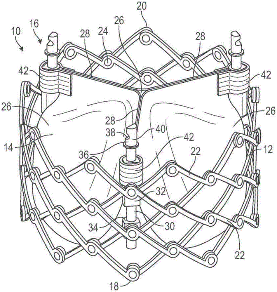
Fig. 1 shows a prosthetic heart valve 10 according to one embodiment. In an exemplary embodiment, the prosthetic valve 10 is configured to be implanted within a native aortic valve. In other embodiments, the prosthetic valve 10 can be configured to be implanted at other locations in the heart, including within a native mitral valve, a native pulmonary valve, and/or a native tricuspid valve.
The prosthetic valve 10 includes three main components: an annular stent or frame 12, a valve structure 14, and one or more actuators (e.g., three actuators 16 in the illustrated embodiment). The frame 12 is configured for supporting the valve structure 14 and for securing the prosthetic valve 10 within the native heart valve. The valve structure 14 is coupled to the frame 12 and/or to the actuator 16 and is configured to allow blood to flow in one direction through the prosthetic valve 10. The actuator 16 is coupled to the frame 12 and is configured to adjust expansion of the frame 12 to a variety of configurations, including one or more functional or expanded configurations (e.g., fig. 1), one or more delivery or compressed configurations (e.g., fig. 2), and/or one or more intermediate configurations. It should be noted that only the frame 12 of the prosthetic valve 10 is shown in fig. 2.
Referring to fig. 1, the frame 12 of the prosthetic valve 10 has a first end 18 and a second end 20. In the illustrated embodiment, the first end 18 of the frame 12 is an inflow end and the second end 20 of the frame 12 is an outflow end. In other embodiments, the first end 18 of the frame 12 may be an outflow end and the second end 20 of the frame 12 may be an inflow end.
The frame 12 of the prosthetic valve 10 can be made of any of a variety of suitable materials, including biocompatible metals and/or biocompatible polymers. Exemplary biocompatible metals that can form the frame include stainless steel, cobalt-chromium alloys, and/or nickel-titanium alloys (also referred to as "NiTi" or "nitinol"). Still referring to FIG. 1, the frame 12 includes a plurality of interconnected struts 22 arranged in a grid-type pattern. The struts 22 are shown in fig. 1 as being positioned diagonally from (or at an angular offset relative to and radially offset from) a longitudinal axis of the prosthetic valve 10 when the prosthetic valve 10 is in the expanded configuration. In other configurations, one or more of the struts 22 may be offset by an amount different than that depicted in fig. 1. Further, as shown in fig. 2, one or more of the struts 22 can be positioned parallel (or at least substantially parallel) to the longitudinal axis of the prosthetic valve 10.
To facilitate movement between the expanded and compressed configurations, the struts 22 are pivotably coupled to one another at one or more pivot joints along the length of each strut. For example, each of the struts 22 may be formed with holes at opposite ends and along the length of the strut. The frame 12 includes a hinge at a location where the posts 22 overlap and are pivotably coupled together via a fastener, such as a rivet or pin 24 extending through holes of the posts. The hinges allow the struts 22 to pivot relative to one another as the frame 12 moves between the radially expanded configuration and the radially compressed configuration, for example, during assembly, preparation, and/or implantation of the prosthetic valve 10.
In some embodiments, the frame 12 may be constructed by forming separate components (e.g., the posts 22 and the pins 24 of the frame 12) and then mechanically assembling and coupling the separate components together. In other embodiments, the struts are not coupled to one another by respective hinges, but are otherwise pivotable or bendable relative to one another to allow radial expansion and contraction of the frame. For example, the frame may be formed (e.g., via laser cutting, electroforming, or physical vapor deposition) from a single piece of material (e.g., a metal tube). Further details regarding the construction of the frame and prosthetic valve are described in U.S. patent No. 10,603,165, U.S. publication nos. 2018/0344456 and 2019/0060057, and international publication No. WO 2020/081893, which are incorporated herein by reference. Additional examples of expandable prosthetic valves that can be used with the delivery devices disclosed herein are described in U.S. patent nos. 9,700,442 and 9,827,093, which are incorporated herein by reference.
The valve structure 14 of the prosthetic valve 10 is coupled to the frame 12 and is configured to regulate blood flow through the prosthetic valve 10 from the inflow end 18 to the outflow end 20. The valve structure 14 can include, for example, a leaflet assembly that includes one or more (e.g., three) leaflets 26 made of a flexible material. The leaflets 26 of the leaflet assembly can be made, in whole or in part, of a biological material, a biocompatible synthetic material, or other such material. Suitable biological materials may include, for example, bovine pericardium (or pericardium from other sources). The leaflets 26 can be arranged to form commissures 28 (e.g., pairs of adjacent leaflets), which commissures 28 can be mounted, for example, to respective actuators 16. Further details regarding transcatheter prosthetic heart valves, including the manner in which the valve structure 14 may be coupled to the frame 12 of the prosthetic valve 10, may be found below by reference to other embodiments and/or in U.S. Pat. nos. 6,730,118, 7,393,360, 7,510,575, 7,993,394, and 8,652,202, and U.S. publication No. 2018/0325665, which are incorporated herein by reference.
The actuator 16 of the prosthetic valve 10 is configured to radially expand and compress the frame 12. For this reason, the actuator 16 may also be referred to as an "expansion mechanism". Actuators 16 are mounted to and spaced about the inner surface of frame 12. Each of the actuators 16 may be configured to form a releasable connection with one or more corresponding actuators of the delivery device, as described further below.
Each of the actuators 16 includes a screw or threaded rod 30, a first anchor 32 (e.g., a cylinder or sleeve), and a second anchor 34 (e.g., a threaded nut). The rod 30 extends through a first anchor 32 and a second anchor 34. The first anchor 32 and the second anchor 34 may be fixed to the frame 12, for example, by respective pins 24 forming a hinge at the junction between the two struts 22. Each actuator 16 is configured to adjust the distance between the attachment locations of the respective first and second anchors 32, 34. Rotating the actuator in a first direction relative to the respective first and second anchors increases the distance between the attachment locations of the respective first and second anchors and axially elongates and radially compresses the frame (e.g., fig. 2). Rotating the actuator relative to the respective first and second anchors in the second direction reduces the distance between the attachment locations of the respective first and second anchors and axially shortens and radially expands the frame (e.g., fig. 1).
For example, each rod 30 may have external threads that engage internal threads of the second anchor 34 such that rotation of the rod 30 causes corresponding axial movement of the first anchor 32 toward or away from the second anchor 34 (depending on the direction of rotation of the rod 30). This causes the hinges supporting the first and second anchors 32, 34 to move closer to one another to radially expand the frame 12 or move farther from one another to radially compress the frame 12 (depending on the direction of rotation of the rod 30).
In other embodiments, the actuator may be a linear-type actuator configured to apply an axially-directed force to the frame to produce radial expansion and compression of the frame. For example, the stem of each actuator may be fixed relative to one of the anchors and slidable relative to the other anchor. For example, the rod may be fixed relative to the second anchor and slidable relative to the first anchor. Thus, in this manner, moving the rod distally relative to the first anchor and/or moving the first anchor proximally relative to the rod causes the frame to compress radially. Conversely, moving the rod proximally relative to the first anchor and/or moving the first anchor distally relative to the rod causes the frame to radially expand.
When reciprocating-type actuators are used, the prosthetic valve can further include one or more locking mechanisms that maintain the frame in the expanded state. The locking mechanism may be a separate component mounted on the frame from the actuator, or it may be a sub-component of the actuator itself. In particular embodiments, the actuator may include a combination expansion and locking mechanism, as further described below and/or in U.S. publication No. 2018/0153689.
Each rod 30 may include an attachment member 36 at a proximal portion of the rod 30. The attachment member may be configured to form a releasable connection with a corresponding actuator of the delivery device. The actuator(s) of the delivery device can apply a force to the stem 30 of the prosthetic valve 10 to radially compress or expand the prosthetic valve 10. The attachment member 36 in the example embodiment includes a notch 38 and a projection 40 that are engageable with corresponding structure of the actuator of the delivery apparatus.
In the illustrated embodiment, the prosthetic valve 10 includes three actuators 16, but in other embodiments a greater or lesser number of actuators can be used. For example, in one embodiment, the prosthetic valve can have one actuator.
The leaflets 26 of the valve structure 14 can have commissure attachment members 42 wrapped around the first anchor 32 of the actuator 16. Further details of the actuator, locking mechanism, and delivery apparatus for actuating the actuator can be found in U.S. publication nos. 2018/0153689, 2018/0325665, and 2019/0060057. Any of the actuators and locking mechanisms disclosed in the previously filed applications can be incorporated into any of the prosthetic valves disclosed herein. Further, any of the locking mechanisms disclosed herein can be incorporated into any of the prosthetic valves disclosed in the previously filed applications. Further, any of the delivery devices disclosed in the previously filed applications may be used to deliver and implant any of the prosthetic valves disclosed herein, and vice versa.
Although not shown in fig. 1, the prosthetic valve 10 can also include one or more skirts (skirts) or sealing members. For example, the prosthetic valve 10 can include an inner skirt mounted on an inner surface of the frame 12. The inner skirt may act as a sealing member to prevent or reduce paravalvular leakage, anchor the leaflets 26 to the frame 12, and/or protect the leaflets from damage caused by contact with the frame during crimping and during the duty cycle of the prosthetic valve. The prosthetic valve 10 can also include an outer skirt mounted on an outer surface of the frame 12. The outer skirt may act as a sealing member for the prosthetic valve by sealing against the tissue of the native valve annulus and thus reducing paravalvular leakage around the prosthetic valve. The inner and outer skirts may be formed of any of a variety of suitable biocompatible materials, including any of a variety of synthetic materials (e.g., PET) or natural tissue (e.g., pericardial tissue). The inner and outer skirts may be mounted to the frame using sutures, adhesives, welding, and/or other means for attaching the skirts to the frame.
Fig. 3 shows a prosthetic heart valve 100 according to another embodiment. The prosthetic valve 100 can include three main components: an annular stent or frame 102, a valve structure (not shown), and one or more actuators 104 (e.g., three in the illustrated embodiment). The frame 102 can be configured to support a valve structure and secure the prosthetic valve 100 within a native heart valve. The valve structure may be coupled to the frame 12 and/or to the actuator 104 and may be configured to allow blood to flow in one direction through the prosthetic valve 100 and restrict blood flow in another direction. The actuator 104 may be coupled to the frame 102 and may be configured to adjust expansion of the frame 102 to a variety of configurations, including one or more functional or expanded configurations (e.g., fig. 3), one or more delivery or compressed configurations (e.g., fig. 4), and/or one or more intermediate configurations. The actuator 104 may also be configured to secure or lock the frame 102 in a desired configuration.
In this manner, the prosthetic valve 100 is generally similar to the prosthetic valve 10. One difference between prosthetic valve 100 and prosthetic valve 10 is that actuator 104 of prosthetic valve 100 separates the expansion/contraction actuation from the locking actuation; while the actuator 16 of the prosthetic valve 10 combines the expansion/contraction actuation with the locking actuation. More specifically, the actuator 104 of the prosthetic valve 100 is configured such that axial (push/pull) actuation of the components adjusts expansion of the frame 102, while separate rotational actuation of the other components locks the frame in a desired configuration. Instead, the actuator 16 of the prosthetic valve 10 is configured such that rotational movement of the components simultaneously adjusts and secures the frame 12 of the prosthetic valve 10. Configuring the actuator 104 with separate expansion and locking actuations may provide several advantages. Additional details and advantages of the actuator 104 of the prosthetic valve 100 are provided below.
The frame 102 of the prosthetic valve 100 includes a first end 106 and a second end 108, and a plurality of struts 110. The struts 110 are connected to one another at joints and are pivotably coupled together (e.g., via pins, rivets, etc.). In this manner, struts 110 form joints that allow frame 102 to be selectively adjusted to an expanded configuration (e.g., fig. 3), a compressed configuration (e.g., fig. 4), and one or more intermediate configurations between the expanded configuration and the compressed configuration.
Although the valve structure of prosthetic valve 100 is not shown for better illustration of actuator 104, the valve structure can include a plurality of leaflets. One or more portions (e.g., commissures) of the leaflets may be coupled to the frame 102 and/or the actuator 104. For example, in one embodiment, the valve structure of the prosthetic valve 100 can be configured to resemble the valve structure 14 of the prosthetic valve 10.
For the sake of brevity, the following description primarily describes a single actuator 104 and its components, even though the prosthetic valve 100 includes three actuators 104 distributed circumferentially around the frame 102. It should be understood that each actuator 104 may be similarly configured and/or operated. It is also understood that in other embodiments, the prosthetic valve 100 can include less than three actuators (e.g., 1-2) or more than three actuators (e.g., 4-6).
Referring now to fig. 5, each actuator 104 of the prosthetic valve 100 can include a first or proximal support member 112, a second or intermediate support member 114, and a third or distal support member 116 (collectively or generally "support members"). The proximal support member 112 may be coupled to the frame 102 at a first location (e.g., at or near the first end 106 of the frame 102), the distal support member 116 may be coupled to the frame 102 at a second location (e.g., at or near the second end 108 of the frame 102), and the intermediate support member 114 may be coupled to the frame 102 at a third location between the first and second locations.
Each actuator 104 may further include a locking member 118 and a locking nut 120. The locking member 118 may be fixedly coupled to the distal support member 116. The locking member 118 extends through the intermediate support member 114 and the proximal support member 112 and is movable (e.g., axially) relative thereto. A lock nut 120 is disposed on the lock member 118 at a location between the proximal and intermediate support members 112, 114. The locking nut 120 is movable relative to the locking member 118.
It should be noted that in some embodiments, the intermediate support member 114 may be omitted.
As shown in fig. 6, the support member of the actuator 104 may be coupled to the frame 102 at a joint of the strut 110. For example, in some embodiments, the support member may include an extension 122, the extension 122 configured to extend through the aperture of the strut 110. In other embodiments, the support member may be coupled to the frame at various other locations (e.g., between joints) and/or by various other means for coupling (e.g., welding, adhesives, fasteners, etc.).
Referring to fig. 7, each support member may include a locking cavity 124 and an actuation cavity 126 extending axially through at least a portion of the support member. The locking cavity 124 and the actuation cavity 126 of each support member may be spaced apart from and parallel to each other. The locking cavity 124 of the actuator 104 extends coaxially through the support member and is configured to receive the locking member 118. An actuation lumen 126 of the actuator 104 extends coaxially through the support member and is configured to receive an actuation shaft of the delivery device.
Still referring to fig. 7, the locking member 118 of the actuator 104 may include a distal portion 128 and a proximal portion 130. The distal end portion 128 of the locking member 118 may be disposed within the locking lumen 124 of the distal support member 116. The locking member 118 can be coupled to the distal support member 116 in various ways (e.g., threads, fasteners, adhesives, welding, and/or other means for coupling). In other embodiments, the locking member 118 and the distal support member 116 may be integrally formed as a single, unitary component. The locking member 118 may extend proximally from the distal support member 116 and through the locking lumen 124 of the intermediate support member 114 toward the proximal support member 112.
As the struts 110 of the frame 102 pivot relative to one another and the frame 102 moves between the expanded, compressed, and intermediate configurations, the proximal and intermediate support members 112, 114 move axially relative to the locking member 118. This is because the locking member 118 is fixed relative to the distal support member 116, and because the axial spacing between the support members changes as the frame 102 moves between the radially expanded/axially shortened configuration and the radially compressed/axially elongated configuration. For example, when the frame 102 is in a radially expanded configuration (e.g., fig. 5), the axial spacing between the support members is relatively small, and thus the proximal end portion 130 of the locking member 118 can extend into the locking lumen 124 of the proximal support member 112. When the frame 102 is in a radially compressed configuration (e.g., fig. 10), the axial spacing between the support members is relatively large, and thus the proximal end portion 130 of the locking member 118 may be axially disposed between the distal end of the proximal support member 112 and the proximal end of the intermediate support member 114.
As described above, the locking nut 120 may be disposed on the locking member 118 and adjustably coupled to the locking member 118. For example, the locking member 118 may include external threads and the locking nut 120 may include corresponding internal threads. In such embodiments, rotating the lock nut 120 in a first rotational direction (e.g., clockwise) relative to the lock member 118 moves the lock nut 120 in a first axial direction (e.g., distal) along the lock member 118, and rotating the lock nut 120 in a second rotational direction (e.g., counterclockwise) relative to the lock member 118 moves the lock nut 120 in a second axial direction (e.g., proximal) along the lock member 118.
The axial position of the lock nut 120 along the length of the lock member 118 limits the extent to which the intermediate support member 114 can move proximally relative to the lock member 118 and the distal support member 116. This is because the lock nut 120 is radially larger than the lock cavity 124 of the intermediate support member 114 and cannot pass therethrough. Thus, the intermediate support member 114 can be slid proximally along the locking member 118 until the locking nut 120 abuts the proximal end of the intermediate support member 114, as shown in fig. 5 and 7. Thus, when the locking nut 120 is disposed toward the proximal end portion 130 of the locking member 118, the frame 102 of the prosthetic valve 100 can be radially compressed to a greater extent than when the locking nut 120 is disposed toward the distal end portion 128 of the locking member 118. In this manner, the lock nut 120 may act as a proximal stop for the intermediate support member 114 along the lock member 118 and as a locking mechanism to prevent the frame 102 from being radially compressed beyond a desired degree.
The intermediate support member 114 and/or the distal support member 116 can limit the extent to which the frame 102 of the prosthetic valve 100 can radially expand. This is because the frame 102 of the prosthetic valve 100 can expand radially outward until the intermediate support members 114 and the distal support members 116 contact each other, which limits further radial expansion of the frame 102 of the prosthetic valve 100. More specifically, the intermediate support member 114 may be translated distally on the locking member 118 until the distal end of the intermediate support member 114 abuts the proximal end of the distal support member 116.
In this manner, the distal support member 116 may act as a distal stop and/or locking mechanism for the intermediate support member 114 along the locking member 118, which prevents the frame 102 from radially expanding beyond a desired degree. Accordingly, the axial length of the intermediate support member 114 and/or the distal support member 116 can be selected to determine the extent to which the frame 102 of the prosthetic valve 100 can be radially expanded. For example, when the intermediate support member 114 and/or the distal support member 116 are relatively long, the frame 102 of the prosthetic valve 100 can expand radially outward to a lesser extent because the intermediate support member 114 travels a shorter distance along the locking member 118 before the distal end of the intermediate support member 114 abuts the proximal end of the distal support member 116 than when the intermediate support member 114 and/or the distal support member 116 are relatively short.
As described above, actuation lumen 126 of actuator 104 may be configured to receive an actuation shaft of a delivery device such that the actuation shaft of the delivery device may extend through proximal support member 112, through intermediate support member 114, and selectively couple to distal support member 116. Additional details regarding the actuator 104 of the prosthetic valve 100 and the actuation shaft of the delivery device are provided below. The actuation shaft can, for example, be used to axially move the distal support member relative to the middle support member 114 and the proximal support member 112 to move the prosthetic valve 100 between the compressed configuration and the expanded configuration.
Fig. 8 shows a schematic view of a delivery device 200. The delivery device 200 can be used, for example, to deliver and manipulate a prosthetic valve to an implantation site within a patient. Exemplary manipulations include: positioning the prosthetic valve relative to the implantation site, radially expanding and compressing the prosthetic valve, securing the prosthetic valve at the implantation site, releasing the prosthetic valve from the delivery device 200, and the like.
Still referring to fig. 8, the delivery device 200 may include one or more catheters. For example, in the illustrated embodiment, the delivery apparatus 200 includes a first or outer catheter 202 and a second or valve catheter 204. The valve catheter 204 may extend axially through the outer catheter 202. In general, the outer catheter 202 can be configured to receive and hold a prosthetic valve in a radially compressed configuration when the prosthetic valve is inserted into a patient and advanced to an implantation location, while the valve catheter 204 can be configured to have a prosthetic valve that can be coupled to a distal portion of the valve catheter and manipulate the prosthetic valve at the implantation location. In some embodiments, the delivery device 200 can include one or more other components (e.g., a guidewire 203, a nose cone 205, etc. (see fig. 13)) and/or one or more additional catheters (e.g., introducers). In other embodiments, the delivery device may omit one or more components (e.g., outer catheter 202).
The outer catheter 202 of the delivery device 200 may include a first handle portion 206 and a first shaft 208. The handle portion 206 may be disposed at a proximal end of the outer catheter 202, and may be configured to be disposed outside of the patient during an implantation procedure. The first shaft 208 may extend distally from the handle portion 206 and may include one or more lumens (not shown), at least one of which is configured such that the valve catheter 204 may extend therethrough. The distal end portion of the first shaft 208 can include a sheath 210, the sheath 210 configured to receive and retain the prosthetic valve in a radially compressed configuration when the prosthetic valve is inserted into a patient and advanced to an implantation location. The sheath 210 can protect the prosthetic valve and/or the patient's native anatomy (e.g., the patient's femoral artery and/or aorta), for example, as the prosthetic valve is advanced to an implantation location (e.g., the patient's native aorta).
In some embodiments, the outer catheter 202 can include a positioning mechanism 212, the positioning mechanism 212 configured to move the outer catheter 202 relative to the valve catheter 204. The positioning mechanism 212 can be used, for example, to deploy a prosthetic valve from the sheath 210 of the outer catheter 202. In some cases, the positioning mechanism 212 may be disposed within the handle portion 206 of the outer catheter 202. Additional details regarding the positioning mechanism can be found, for example, in U.S. patent nos. 8,652,202, 9,155,619, 9,867,700, and 10,588,744, which are incorporated herein by reference.
The outer catheter 202 may, in some embodiments, include a steering mechanism 214, the steering mechanism 214 being configured such that a user may position the distal end portion of the first shaft 208 relative to the patient's natural anatomy from a location outside of the patient's body. In some cases, the steering mechanism 214 may be disposed within the handle portion 206 of the outer catheter 202. Additional details regarding the outer catheter and steering mechanism can be found, for example, in U.S. patent nos. 10,076,638 and 10,653,862, which are both incorporated herein by reference.
The valve catheter 204 of the delivery device 200 can include a second handle portion 216, a second shaft 218, one or more third shafts 220, one or more actuation shafts 222, and one or more locking shafts 224. For example, in the illustrated embodiment, there are three each of the shafts 220, 222, 224. In other embodiments, each of the shafts 220, 222, 224 may be less than three (e.g., 1-2) or more than three (e.g., 4-6).
The proximal end portions of the shafts 218, 220, 222, 224 may be coupled to and/or housed within the second handle portion 216. The shafts 218, 220, 222, 224 can extend distally from the second handle portion 216, and the shafts 218, 220, 222, 224 can move (e.g., axially and/or rotationally) relative to the second handle portion 216 and relative to each other. The second handle portion 216 may be configured to move the valve catheter 204 relative to the outer catheter 202 and/or move the shafts 218, 220, 222, 224 relative to each other and/or other components of the delivery device. The second shaft 218 may be configured to receive a third shaft 220. The third shaft 220 may extend axially through the second shaft 218 and may be configured to receive at least portions of the shafts 222, 224 and engage an actuator of the prosthetic valve. The actuation shaft 222 can extend axially through the third shaft 220 and can be configured to actuate an actuator of the prosthetic valve. The locking shaft 224 may extend axially through the third shaft 220 and may be configured to actuate and/or lock an actuator of the prosthetic valve. Additional details of these components and their interaction together and/or with the prosthetic valve are described below.
In some embodiments, the second handle portion 216 can include a second positioning mechanism 226, a second manipulation mechanism 228, an actuation mechanism 230, and/or a locking mechanism 232. The second positioning mechanism 226 may be configured to move the third shaft 220 relative to the second shaft 218. The second steering mechanism 228 may be configured to steer a distal portion of the second shaft 218 (and thus the shafts 220, 222, 224). The actuation mechanism 230 may be configured to move (e.g., collectively or individually) the actuation shaft 222 relative to the third shaft 220. The locking mechanism 232 may be configured to move the locking shaft 224 relative to the third shaft 220 (e.g., collectively or individually). The mechanism of the delivery device 200 may include mechanical components (e.g., knobs, handles, buttons, levers, gears, drive screws, nuts, pull wires, etc.) and/or electronic components (e.g., motors, circuits, wires, etc.). These mechanisms may, for example, make positioning and/or movement of the shafts relative to each other relatively easier than manual operation. These mechanisms may also allow one or more of these movements to be automated.
In other embodiments, one or more of the mechanisms 226, 228, 230, 232 may be omitted from the second handle portion 216, and the shafts 218, 220, 222, 224 may be manually positioned and/or moved (e.g., pushed/pulled, rotated, etc.) relative to one another. Configuring the second handle portion 216 in this manner may, for example, reduce the number of components and/or make the device simpler and/or more cost effective to manufacture.
The second shaft 218 of the valve catheter 204 can be configured to extend distally from the second handle portion 216 of the valve catheter 204 and through the first handle portion 206 of the outer catheter 202 and the first shaft 208 such that a distal end portion 234 of the second shaft extends distally beyond a distal end portion of the first shaft 208. This may allow deployment of the prosthetic valve (which may be coupled to the distal end portion of the valve catheter 204) from the sheath 210 of the outer catheter 202 by moving the second shaft 218 (and thus the shafts 220, 222, 224) relative to the first shaft 208.
The second shaft 218 may include one or more (e.g., three) cavities. Each cavity may be configured to receive a respective third shaft 220.
Each of the third shafts 220 may be configured to extend distally from the second handle portion 216 through a respective cavity of the second shaft 218 such that a distal end portion of the third shaft 220 may be disposed distally relative to a distal end portion of the second shaft 218. In this manner, the distal end portion 236 of the third shaft 220 can contact the proximal support member of the actuator of the prosthetic valve, as shown in fig. 10. Thus, third shaft 220 may, for example, be used to exert a distally directed force on proximal support member 112 (e.g., while actuating shaft 222 exerts a proximally directed force on distal support member 116).
As shown in fig. 9, each of the third shafts 220 may include a plurality of cavities, including an actuation cavity 238 and a locking cavity 240. The actuation cavity 238 of each third shaft 220 may be configured to receive a respective actuation shaft 222. The lock cavity 240 of each third shaft 220 may be configured to receive a respective lock shaft 224.
Still referring to fig. 9, each actuation shaft 222 may be configured to extend distally from the second handle portion 216 through the actuation lumen 238 of the respective third shaft 220 such that a distal end portion of the actuation shaft 222 may be disposed distally relative to the distal end portion 236 of the third shaft 220. Thus, the prosthetic valve 100 can be releasably coupled to the distal end portion of the actuation shaft 222.
The distal portion of each actuation shaft 222 can include a coupling element configured to releasably couple the actuation shaft 222 to a respective actuator of the prosthetic valve. The coupling element may be coupled to the actuation shaft 222 or integrally formed with the actuation shaft 222. For example, in the illustrated embodiment, the coupling element of the actuation shaft 222 includes a threaded element 242 disposed at a distal portion of the actuation shaft 222. The threaded element 242 includes external threads configured to mate with corresponding internal threads disposed within the actuation lumen 126 of the distal support member 116 of the prosthetic valve 100, as shown in fig. 10. When the threaded element 242 is coupled to the distal support member 116 of the prosthetic valve 100, the actuation shaft 222 can be used to actuate the actuator 104 of the prosthetic valve 100 and thereby move the prosthetic valve 100 between a radially expanded configuration and a radially compressed configuration, as explained further below.
Referring again to fig. 9, each locking shaft 224 may be configured to extend distally from the second handle portion 216 through the locking cavity 240 of the respective third shaft 220 such that a distal end portion of the locking shaft 224 may be disposed distally relative to the distal end portion 236 of the third shaft 220. Thus, the prosthetic valve 100 can be releasably coupled to the distal end portion of the locking shaft 224.
The distal portion of each locking shaft 224 can include a cavity or aperture 244 configured to receive the locking member 118 of the prosthetic valve 100. In some embodiments, the bore 244 of the locking shaft 224 can include internal threads configured to mate with corresponding external threads of the locking member 118 of the prosthetic valve 100 such that the locking shaft 224 can be releasably coupled to the locking member 118. Thus, rotating the locking shaft 224 of the delivery device 200 relative to the locking member 118 of the prosthetic valve 100 causes the locking shaft 224 to translate proximally or distally along the locking member 118, depending on the direction in which the locking shaft 224 is rotated.
The distal portion of each locking shaft 224 can include a mating element (e.g., an extension 246) configured to mate with a corresponding mating element (e.g., an extension 132) of the locking nut 120 of the prosthetic valve 100. The mating elements of the lock shaft 224 and the lock nut 120 may allow the lock shaft 224 and the lock nut 120 to be selectively mated together. The mating elements may be configured such that when the lock shaft 224 and the lock nut 120 are mated together by the mating elements, rotating the lock shaft 224 relative to the lock member 118 in a first direction (e.g., clockwise) causes the lock nut 120 along with the lock shaft 224 to rotate relative to the lock member 118 in the first direction. The mating elements may also be configured such that when the lock shaft 224 and the lock nut 120 are mated together by the mating elements, rotating the lock shaft 224 relative to the lock member 118 in a second direction (e.g., counterclockwise) causes the lock shaft 224 to rotate relative to the lock nut 120 and the lock nut 120 to retain its position relative to the lock member 118. In other words, the mating feature may be configured such that the lock shaft 224 may be used to move the lock nut 120 in a first axial direction (e.g., distally) rather than in a second axial direction (e.g., proximally). In this manner, the locking shaft 224 along with the locking nut 120 can be used to lock the frame 102 of the prosthetic valve 100 in a desired radially expanded configuration, as described further below.
The prosthetic valve 100 can be releasably coupled to the distal end portion of the delivery apparatus 200 to form a delivery assembly, as shown in fig. 11. This can be accomplished, for example, by positioning the first end 106 of the prosthetic valve 100 near the distal end portion of the delivery device 200 such that the distal end portion 236 of the third shaft 220 is aligned with the proximal support member 112 of the prosthetic valve 100. The actuation shaft 222 of the delivery device 200 can then be distally advanced through the respective actuation lumen 126 of the prosthetic valve 100 until the threaded element 242 of the actuation shaft 222 contacts the respective actuation lumen 126 of the distal support member 116. Actuation shaft 222 may then be releasably coupled to distal support member 116 by rotating actuation shaft 222 in a first direction (e.g., clockwise) relative to distal support member 116 such that threaded element 242 of actuation shaft 222 mates with distal support member 116. The locking shaft 224 of the delivery device 200 can then be advanced distally through the respective locking lumen 124 of the prosthetic valve 100 until the distal end portion of the locking shaft 224 contacts the respective locking member 118 of the prosthetic valve 100. The locking shaft 224 may then be releasably coupled to the locking member 118 by: the locking shaft 224 is rotated in a first direction (e.g., clockwise) relative to the locking member 118 such that the internal threads of the locking shaft 224 threadably mate with the external threads of the respective locking member 118 and the proximal end of the locking member 118 is disposed within the respective bore 244 of the locking shaft 224.
The locking nut 120 of the prosthetic valve 100 can be disposed at or near the proximal end portion 130 of the locking member 118. This can allow the intermediate support member 114 of the prosthetic valve 100 to slide proximally relative to the locking member 118, which allows the prosthetic valve 100 to move to the radially compressed configuration. With the locking nut 120 disposed at or near the proximal end portion 130 of the locking member, the intermediate support member 114 of the prosthetic valve 100 can also slide distally relative to the locking member 118, which allows the prosthetic valve to be moved to a radially expanded configuration.
With the prosthetic valve 100 coupled to the delivery apparatus 200, the prosthetic valve 100 can be moved to a radially compressed configuration. This can be accomplished by moving the actuation shaft 222 distally relative to the third shaft 220, which applies an axial tension to the frame 102 of the prosthetic valve 100. Additionally or alternatively, this can be achieved by applying a radial compressive force to the frame 102 of the prosthetic valve (e.g., by a crimping device). This causes the frame 102 of the prosthetic valve 100 to axially elongate and radially compress, as shown in fig. 12.
The radially compressed prosthetic valve 100 can then be loaded into the sheath 210 of the delivery apparatus 200 (see fig. 13) (or advanced into the vasculature of a patient in a sheath-less configuration). This may be achieved by moving the outer catheter 202 distally relative to the valve catheter 204 and/or by moving the valve catheter proximally relative to the outer catheter 202.
The delivery assembly can then be inserted into the patient, and the prosthetic valve 100 can be advanced to the implantation location. The delivery assembly can be configured for various implantation locations (e.g., native aortic, mitral, tricuspid, and/or pulmonary valves) and/or delivery routes (e.g., transfemoral, transapical, transseptal, etc.). For example, in an exemplary embodiment, the delivery assembly is configured for implantation of the prosthetic valve 100 within a native aortic valve using a transfemoral approach.
Fig. 13 shows the distal portion of the delivery device 200, the delivery device 200 being inserted through the patient's native aortic annulus 300 such that the nose cone 205 and sheath 210 are disposed within the patient's left ventricle 302. The prosthetic valve 100 can then be deployed from the sheath 210 of the delivery device 200, as shown in fig. 14. This may be accomplished, for example, by moving the first shaft 208 of the outer catheter 202 proximally relative to the valve catheter 204 (e.g., via the positioning mechanism 212). To better illustrate the prosthetic valve 100, the guidewire 203 and nose cone 205 are not shown in fig. 14-16.
With the prosthetic valve 100 exposed from the sheath 210 of the delivery device 200, the delivery device 200 can be used to position the prosthetic valve 100 within the native annulus and radially expand the prosthetic valve 100. Positioning the prosthetic valve 100 can include axial and/or rotational movement of the first and second shafts 208, 218 and/or actuating one or more of the first and second manipulation mechanisms 214, 228.
Referring to fig. 10, the prosthetic valve 100 can be radially expanded by moving the actuation shaft 222 of the delivery device 200 proximally relative to the third shaft 220 of the delivery device 200 (e.g., by actuating the actuation mechanism 230) and/or by moving the third shaft 220 distally relative to the actuation shaft 222. This causes the delivery device 200 to exert an axial compressive force on the actuator 104 frame 102 of the prosthetic valve 100. Specifically, the actuation shaft 222 applies a proximally directed force to the distal support member 116 of the prosthetic valve 100, and the third shaft 220 applies an opposing distally directed force to the proximal support member 112 of the prosthetic valve 100. As a result, struts 110 of frame 102 pivot relative to one another and prosthetic valve 100 radially expands, as shown in fig. 15.
The user can select the degree to which prosthetic valve 100 is radially expanded. For example, the user can radially expand prosthetic valve 100 to a predetermined radial expansion. The user can then determine whether paravalvular leakage is present. If the user determines that adjustments are needed (e.g., in positioning and/or expansion), the user can further radially expand the prosthetic valve 100 by moving the actuation shaft 222 proximally relative to the third shaft 220. Alternatively, the user can radially compress prosthetic valve 100 by moving actuation shaft 222 distally relative to third shaft 220, and vice versa. This reduces axial compression on the frame 102 of the prosthetic valve 100, which allows the frame 102 to axially elongate and radially compress. The prosthetic valve 100 can be repositioned relative to the native aortic annulus 300. Prosthetic valve 100 can be further compressed and retracted into sheath 210 of delivery device 200.
Once the prosthetic valve 100 is desirably positioned and radially expanded relative to the native aortic annulus 300, the prosthetic valve 100 can be locked in a desired radially expanded configuration. This can be achieved by actuating the locking mechanism 232 of the delivery device 200 such that the locking shaft 224 is rotated in a first direction and moved distally relative to the locking member 118 of the prosthetic valve 100. Referring again to fig. 10, when the locking shaft 224 engages the locking nut 120, the locking nut 120 of the prosthetic valve 100 also rotates in the first direction and moves distally relative to the locking member 118. The locking nut 120 can be moved distally relative to the locking member 118 until the locking nut 120 contacts the intermediate support member 114 (see, e.g., fig. 5). Thus, the locking nut 120 limits proximal movement of the intermediate support member 114 relative to the locking member 118, thereby limiting radial compression of the frame 102 of the prosthetic valve 100.
Because the actuation shaft 222 is subject to the load used to expand the prosthetic valve 100, the locking shaft 224 can rotate relative to the locking member 118 with relative ease. This may, for example, reduce the likelihood that the lock shaft 224, lock nut 120, and/or lock member 118 will bind and/or be damaged (e.g., stripped threads).
With the prosthetic valve 100 secured within the native aortic annulus and the radial expansion of the prosthetic valve 100 locked, the prosthetic valve 100 can be released from the delivery device 200 and the delivery device 200 can be removed from the patient. The locking shaft 224 of the delivery device 200 can be released from the prosthetic valve 100 by actuating the locking mechanism 232 of the delivery device 200 such that the locking shaft 224 is rotated in the second direction and moved proximally relative to the locking nut 120 and the locking member 118 of the prosthetic valve 100 until the locking shaft 224 is decoupled from the proximal end portion 130 of the locking member 118 and the locking member 118 is withdrawn from the aperture 244 of the locking shaft 224. The actuation shaft 222 of the delivery device 200 can be released from the prosthetic valve 100 by rotating the actuation shaft 222 relative to the distal support member 116 of the prosthetic valve 100 in a second direction until the actuation shaft 222 is withdrawn from the locking lumen 126 of the distal support member 116.
With the prosthetic valve 100 released from the delivery apparatus 200, the third shaft 220 of the delivery apparatus 200, along with the actuation shaft 222 and the locking shaft 224, can be moved proximally relative to the second shaft 218 such that the shafts 220, 222, 224 are disposed within the second shaft 218 (see fig. 16). The first catheter 202 and the second catheter 204 may be withdrawn from the patient.
A delivery assembly including prosthetic valve 100 and delivery apparatus 200 can provide one or more advantages over existing mechanically expandable prosthetic valves. For example, the delivery assembly separates the actuation mechanism from the locking mechanism. This can reduce the radial profile of the actuator 104 of the prosthetic valve 100 because the actuation component and the locking component are adjacent rather than coaxial, which in turn can reduce the radial profile of the prosthetic valve in the compressed configuration. Yet another advantage of this configuration is that when the locking shaft 224 and locking nut 120 are rotated, there is little or no load thereon, as the actuation shaft 222 bears the load (e.g., tension) required to expand the prosthetic valve 100, which can reduce binding and improve reliability of the assembly. Further, the locking shaft 224 may be solid (except for the aperture 244 at the distal portion), which may increase the strength of the shaft against forces that may damage the shaft.
The separation of the actuation mechanism from the locking mechanism may also increase the redundancy (redundancy) and thus the safety of the prosthetic valve by providing multiple actuation mechanisms and multiple locking mechanisms. For example, if one of the locking mechanisms of the prosthetic valve 100 fails, there are other locking mechanisms that will prevent the prosthetic valve from radially compressing. Further, instead of or in addition to the actuation shaft, the prosthetic valve 100 can be expanded by rotating the locking nut 120 via the locking shaft 224 to expand/compress the prosthetic valve 100. In this manner, the locking nut 120 and locking member 118 function similarly to the stem 30 of the prosthetic valve 10.
Such a configuration can allow the prosthetic valve 100 to expand relatively quickly via an axial (also can be referred to as "linear") actuation mechanism, while also ensuring that the prosthetic valve 100 is secured in the expanded configuration via a rotational locking mechanism.
Fig. 17 shows a prosthetic heart valve 400 according to another embodiment. Prosthetic valve 400 is similar to prosthetic valve 100 in that it includes a frame 402, one or more actuators 404 for expanding/compressing frame 402, and a valve structure 406 configured to allow blood to flow through frame 402 in one direction. One difference between prosthetic valve 400 and prosthetic valve 100 is that proximal support member 408 of actuator 404 includes a window 410, window 410 being configured to receive leaflet commissures 412 of valve structure 406, as shown in fig. 18-19. Additional details regarding these components are provided below.
Referring to fig. 18, the actuators 404 of the prosthetic valve 400 can each include a proximal support member 408, a middle support member 414, a distal support member 416, a locking member 418, and a locking nut 420. As shown in fig. 19, the support members 408, 414, 416 may each have an actuation cavity 421 and a locking cavity 423. The actuation lumen 421 may be configured to receive an actuation shaft of a delivery device. The locking cavity 423 may be configured to receive the locking member 418 and the locking shaft of the delivery device.
The middle support member 414, distal support member 416, locking member 418, and locking nut 420 of the prosthetic valve 400 can be configured similar to the middle support member 114, distal support member 116, locking member 118, and locking nut 120, respectively, of the prosthetic valve 100.
Referring again to fig. 18, the proximal support member 408 of each actuator 404 may include an actuation tube 422, a locking tube 424, and one or more connecting portions 426 (e.g., two in the illustrated embodiment). The actuation lumen 421 may extend axially through the actuation tube 422, and the locking lumen 423 may extend axially through the locking tube 424. The tubes 422, 424 may be spaced apart from one another, and a connecting portion 426 may be disposed at and extend between proximal and/or distal portions of the tubes 422, 424. In this manner, the tubes 422, 424 and the connecting portion 426 define the window 410. As shown in fig. 19, the window 410 can be configured to receive a commissure 412 of the valve structure 406. The connecting portion 426 may also be configured to mount the proximal support member 408 to the frame 402.
Referring now to fig. 20, the commissures 412 can be formed by the lugs 428 of adjacent pairs of leaflets 430. The lugs 428 of the pair of leaflets 430 can extend radially through the windows 410 of the proximal support member 408. The lugs 428 may then circumferentially splay away from each other and extend at least partially around the respective tubes 422, 424 of the proximal support member 408.
In some embodiments, a coupling member 432 (e.g., a fabric strip) can be provided that is configured to secure the tabs 428 of the leaflets 430 to the tubes 422, 424 and/or to protect the leaflets 430 from the frame 402 and the actuators 404. The coupling member 432 can extend between the leaflet 430 and the tubes 422, 424. The coupling member 432 and the lug 428 may be coupled together in various ways (e.g., via a suture 434, an adhesive, and/or other coupling means).
In some embodiments, the prosthetic valve 400 can include a wedge element 436. Wedge-shaped elements 436 can be radially disposed between commissures 412 of leaflets 430 and frame 402. Wedge-shaped element 436 can, for example, help secure tabs 428 of leaflets 430 together (e.g., via sutures 434) and/or reduce wear between leaflets 430 and frame 402.
Attaching the commissures 412 of the leaflets 430 to the proximal support member 408 of the actuator 404 in this manner can provide several advantages. For example, such a configuration may provide a radial space between the commissures 412 and the frame 402, as shown in fig. 21. The radial space can reduce the likelihood that the leaflets 430 will rub against the frame 402, which can extend the life of the prosthetic valve 400. The radial space may also prevent smooth muscle cells from proliferating from the native tissue toward the commissures 412, which may improve the functionality and/or longevity of the prosthetic valve 400.
Fig. 22 shows a proximal support member 500 according to another embodiment. The proximal support member 500 can be used, for example, in place of the proximal support member 408 of the prosthetic valve 400. The proximal support member 500 is configured to be generally similar to the proximal support member 408, but the proximal support member 500 has an open slot 502 instead of the closed window 410 of the proximal support member 408. As shown in fig. 23, forming the proximal support member 500 in this manner can allow the valve structure (e.g., valve structure 406) to be at least partially pre-assembled, and the commissures 412 can then be inserted into the open slots 502 of the proximal support member 500. This may, for example, make assembly of the prosthetic valve easier, improve manufacturing yield, and/or improve quality.
The proximal support member 500 may include an actuation tube 504, a locking tube 506, and a connecting portion 508. The tubes 504, 506 may be spaced apart from each other and the connecting portion 508 may extend between the distal portions of the tubes 504, 506. The actuation tube 504 may include an actuation lumen 510, the actuation lumen 510 configured to receive an actuation shaft of a delivery device (e.g., actuation shaft 222). The locking tube 506 may include a locking lumen 512, the locking lumen 512 configured to receive a locking shaft of a delivery device (e.g., locking shaft 224). The connecting portion 508 can be configured to mount the proximal support member 500 to a frame (e.g., frame 402) of a prosthetic valve.
The slot 502 of the proximal support member 500 is defined by tubes 504, 506 and a connecting portion 508. In the illustrated embodiment, the slot 502 is generally "U" shaped. In other embodiments, the slots 502 can be tapered or "V" shaped or include other shapes configured to receive the commissures of the valve structure.
As shown in fig. 23, the commissures 412 of the valve structure 406 can be inserted into the slots 502 of the proximal support member 500. The valve structure can couple the tabs 428 of the leaflets 430 together via coupling members 432, wedges 436, and sutures 434. With the commissures 412 disposed in the slots 502, the commissures 412 can be secured to the proximal support member 500 by wrapping the coupling member 432 around the tubes 504, 506 of the proximal support member 500 and suturing the coupling member 432 to the tubes 504, 506 in a manner similar to that shown in fig. 20. Additionally or alternatively, the commissures 412 may be secured to the proximal support member 500 by other coupling means, such as adhesives, fasteners, and the like.
Fig. 24 shows a prosthetic heart valve 600 according to another embodiment. The prosthetic valve 600 can include a frame 602 and one or more actuators 604. Although not shown, the prosthetic valve 600 can also include a valve structure and/or one or more sealing skirts. The prosthetic valve 600 is configured to be generally similar to the prosthetic valve 400, except that the frame 602 of the prosthetic valve 600 includes one or more flared apices 606 at the outflow end 608 of the frame and adjacent to the actuator 604, as best shown in fig. 25.
Referring to fig. 25, each flared apex 606 of frame 602 may include a first portion or segment 606a and a second portion or segment 606 b. The first segment 606a can extend radially outward relative to the body 610 of the frame 602 and relative to the actuator 604 to create a space or gap between the frame 602 and the actuator 604 (and a commissure that can be coupled to the actuator). The second segment 606b may extend radially inward from the first segment 606b and radially overlap (at least partially) with the actuator 604. The second segment 606b may help reduce contact between the apex of the frame 602 and the native tissue, which may reduce trauma to the native tissue (e.g., at the sinotubular junction).
In some embodiments, the body 610 of the frame 602 may taper radially outward from the inflow end 612 to the outflow end 608. The taper or bevel angle alpha can be measured relative to the vertical line. The mold angle α can vary. For example, in some embodiments, the mold angle α can be in the range of 2-15 degrees. In some embodiments, the tilt angle α can be in the range of 5-10 degrees.
As shown in fig. 24, the frame 602 of the prosthetic valve 600 has three flared apices 606 that are circumferentially aligned with the actuators 604. In other embodiments, the frame may include fewer or more than three open vertices. For example, in some embodiments, each vertex of the outflow end of the frame can be flared. As another example, the prosthetic valve can have two actuators, and the frame can include two flared vertices circumferentially aligned with the actuators.
Fig. 26 shows a prosthetic heart valve 700 according to yet another embodiment. The prosthetic valve 700 can include a frame 702 and one or more actuators 704 (e.g., three in the illustrated embodiment). The frame 702 of the prosthetic valve 700 can be configured to support a valve structure (not shown) and anchor the prosthetic valve 700 in a native annulus (e.g., the native aortic annulus). An actuator 704 is coupled to the frame 702 and is configured to move the frame 702 between a radially expanded configuration and a radially compressed configuration. The actuator 704 is also configured to lock the frame 702 in a desired radial configuration.
The frame 702 of the prosthetic valve 700 can include a plurality of pivotally connected struts configured in a manner similar to the frame 12 of the prosthetic valve 10.
As shown in fig. 26-29, each actuator 704 may include an actuation plate 706 and a locker housing 708. The actuation plate 706 can be coupled to a first end (e.g., an inflow end portion) of the frame 702, and the locker housing 708 can be coupled to a second end (e.g., an outflow end portion) of the frame 702. The actuation plate 706 may be radially disposed within the locker housing 708 in a piston-cylinder like manner and may be selectively axially movable relative to the locker housing 708, with the actuation plate 706 acting like a piston and the locker housing 708 acting like a cylinder. Thus, when actuation plate 706 and lock housing 708 are moved axially toward one another, frame 702 expands radially and contracts axially, and when actuation plate 706 and lock housing 708 are moved axially away from one another, frame 702 compresses radially and elongates axially.
Referring now to fig. 27, the actuation plate 706 of the actuator 704 may include a base 710 and a plurality of jaws extending from the base 710. For example, the illustrated embodiment includes a first jaw 712a and a second jaw 712b (collectively or collectively "jaws 712"). In other embodiments, actuation plate 706 may include additional jaws (e.g., 3-4 jaws). The base 710 may be configured to couple the actuation plate 706 to the frame 702. The jaws 712 may be configured to releasably couple the actuation plate 706 to a delivery device, and the delivery device may be configured to move the jaws 712 relative to the locker housing 708, which results in expansion and compression of the frame 702. Jaws 712 may also be configured to selectively engage lock housing 708 to limit relative movement between actuation plate 706 and lock housing 708 and to limit further radial expansion and compression of frame 702.
The base 710 of the actuation plate 706 may be coupled to the frame 702 in various ways. For example, the base 710 may include an opening 714, the opening 714 configured to receive a fastener (e.g., a rivet or screw) that couples the actuation plate 706 to the frame 702. In addition to or as an alternative to fasteners, the base 710 may be coupled to the frame by welding, adhesives, and/or other coupling means.
Referring to fig. 27, the jaws 712 of the actuation plate 706 may include distal portions 716 and proximal portions 718. The distal end portions 716 of the jaws 712 may be coupled to the base 710 of the actuation plate 706.
As shown in fig. 27-28, the jaws 712 may be configured to be movable relative to each other between an open state (e.g., fig. 27) and a closed state (e.g., fig. 28). In the open state, the jaws 712 are spaced apart from each other such that an actuation shaft of the delivery device may be disposed between the jaws 712 (see fig. 32). In the closed state, the jaws 712 are relatively closer together so that the jaws 712 can engage the actuation shaft and secure it between the jaws 712 (see fig. 33). Additional details regarding the interaction between the actuation plate 706 and the delivery device 800 are provided below.
Referring to fig. 28, the jaw 712 may be configured such that in a closed state, a proximal portion 718 of the jaw 712 includes an opening 720. The opening 720 may be configured to receive an actuation shaft of a delivery device and limit relative movement between the jaws 712 and the actuation shaft, as shown in fig. 33. Referring again to fig. 28, the opening 720 includes a first portion 722 and a second portion 724 configured to receive respective portions of an actuation shaft.
The jaw 712 may include a projection or lug 726 extending outwardly therefrom. The jaws 712 may be configured such that when the jaws 712 are in an open state, the lugs 726 engage the latch housing 708, thereby restricting relative movement between the actuation plate 706 and the latch housing 708. The ledge 726 may also act as a distal stop for a locking shaft of a delivery device (see fig. 36), as described further below.
In some embodiments, the jaws 712 of the actuation plate 706 may be configured to be biased toward an open state. This may be accomplished, for example, by forming the jaws 712 of the actuation plate 706 from a flexible, resilient material (e.g., stainless steel, nitinol, and/or other biocompatible metals and/or polymers) and forming (e.g., shaping) the jaws 712 in an open state. Additionally or alternatively, a biasing member (e.g., a spring) configured to bias the jaws to the open state may be coupled to the jaws.
Referring now to fig. 29, the locker housing 708 of the actuator 704 may comprise a cavity 728 and one or more slots 730. Cavity 728 of lock housing 708 may be configured such that actuation plate 706 and one or more components of a delivery device may be disposed therein. The slot 730 may be configured to receive the tab 726 (fig. 28) of the actuation plate 706 when the jaws 712 of the actuation plate 706 are in the open state. When the jaws 712 of the actuation plate 706 are in the open state, the ledge 726 of the actuation plate 706 may extend into the slot 730, thereby restricting relative movement between the actuation plate 706 and the latch housing 708. When the jaws 712 of the actuation plate 706 are in the closed state, the tabs 726 of the actuation plate 706 disengage the slots 730, thereby allowing relative movement between the actuation plate 706 and the latch housing 708. The delivery device can be used to selectively engage/disengage the tabs 726 of the actuation plate 706 with the slots 730 of the locker housing 708 to move the prosthetic valve 700 between the expanded and compressed configurations.
The slots 730 may be axially spaced relative to one another. In some embodiments, the slots 730 may also be arranged in one or more rows distributed circumferentially around the sleeve. For example, in the illustrated embodiment, the locker housing 708 includes two columns of slots 730, each column including 11 slots. In other embodiments, the locker housing 708 may include less or more than two columns of slots (e.g., 1 column or 3-4 columns).
The locker housing 708 may also include an opening 732 disposed at a distal portion of the locker housing 708. The opening 732 of the locker housing 708 may be configured such that the base 710 of the actuation plate 706 is exposed from the locker housing 708 when the actuation plate 706 is disposed within the locker housing 708. This may, for example, allow the base 710 of the actuation plate 706 to be coupled to the frame 702, as shown in fig. 26.
Fig. 30 shows a delivery device 800 according to an embodiment. The prosthetic valve 700 can be coupled to a distal portion of the delivery apparatus 800 to form a delivery assembly, and the delivery apparatus 800 can be used to implant the prosthetic valve 700 within a patient.
Referring to fig. 30-31, a delivery apparatus 800 (which may also be referred to as a "valve catheter") may include a handle 802, a first shaft 804, one or more second shafts 806, one or more locking shafts 808, one or more actuation shafts 810, and an irrigation mechanism 812. The handle 802 may be configured to steer the shafts relative to each other. The shafts 804, 806, 808, 810 can be configured to couple the prosthetic valve 700 to the delivery device 800, to position the prosthetic valve 700, and/or to expand, compress, and lock the prosthetic valve 700 in a desired radially expanded configuration.
In some embodiments, the delivery apparatus 800 includes three each of the shafts 806, 808, 810 (i.e., one set of shafts 806, 808, 810 for each actuator 704 of the prosthetic valve 700). For purposes of illustration, only one set of axes 806, 808, 810 is shown in FIG. 31. In other embodiments, the delivery apparatus 800 can include less than three (e.g., 1-2) or more than three (e.g., 4-5) of each of the shafts 806, 808, 810 (e.g., depending on the number of actuators included with the prosthetic valve).
The handle 802 may include a first portion 814 and a second portion 816 movably coupled together. The shafts 804, 806 may be coupled to a first portion 814 of the handle 802, and the shafts 808, 810 may be coupled to a second portion 816 of the handle 802. Thus, the first and second portions 814, 816 of the handle 802 may be used to move the shafts 804, 806 relative to the shafts 808, 810.
Referring now to fig. 30-31, the first shaft 804 may extend distally from the first portion 814 of the handle 802 and may include one or more lumens for accommodating other shafts of the delivery device. For example, the first shaft 804 may include one or more first cavities 818 (e.g., three in the illustrated embodiment). Each of the first cavities 818 of the first shafts 804 may be configured to receive a respective second shaft 806. In some embodiments, the first shaft 804 may further include one or more additional lumens, such as a guidewire lumen 820. The guidewire lumen 820 may be centrally disposed. The first lumens 818 may be disposed radially outward relative to the guidewire lumen 820 and circumferentially spaced relative to each other.
The second shaft 806 may extend distally from a respective first lumen 818 of the first shaft 804 and may be configured to contact a locker housing 708 (fig. 26) of the prosthetic valve 700. Thus, the second shaft 806 of the delivery device 800 can be used to apply a distally directed force to the lock housing 708 of the prosthetic valve 700, which can oppose the proximally directed force applied by the actuation shaft 810 of the delivery device 800 to the actuation plate 706 of the prosthetic valve 700, thereby enabling expansion of the prosthetic valve 700 by relative axial movement between the actuation plate 706 of the prosthetic valve 700 and the lock housing 708.
In some embodiments, a proximal portion of the second shaft 806 may be coupled to the first portion 814 of the handle 802, and the second shaft 806 may extend through the respective first lumen 818 of the first shaft 804 to the distal end of the first shaft 804. In other embodiments, the second shaft 806 may be a relatively short tube coupled to the distal end portion of the first shaft 804 but not extending proximally to the handle 802. In either case, each of the second shafts 806 may include a second cavity 822, and the second cavities 822 may be configured to receive the respective locking shafts 808.
The locking shafts 808 may extend distally from the second portion 816 of the handle 802 and through the respective second lumens 822 of the second shaft 806 (and, in embodiments where the second shaft 806 is disposed only at the distal end of the first shaft 804, through the respective first lumens 818 of the first shaft 804 before extending through the second lumens 822). Each of the locking shafts 808 may include a third cavity 824. The third cavities 824 may be configured to receive respective actuation shafts 810. The third lumen 824 can also be configured such that the locking shaft 808 can be advanced over a respective pair of jaws 712 of the prosthetic valve 700 to move and/or maintain the jaws 712 of the actuator 704 of the prosthetic valve 700 in a closed state.
The actuation shafts 810 may extend distally from the second portion 816 of the handle 802 and through the third lumen of the respective locking shaft 808. The actuation shaft 810 can be releasably coupled to the jaws 712 of the actuator 704 of the prosthetic valve 700 via the locking shaft 808 of the delivery apparatus 800. The actuation shaft 810 can thus be used to radially expand and compress the prosthetic valve 700 when the actuation shaft 810 is moved relative to the second shaft 806 (along with the locking shaft 808).
The distal end portion of the actuation shaft 810 can include mating features configured such that the actuation shaft 810 can be releasably coupled to the jaws 712 of the actuator 704 of the prosthetic valve 700. For example, referring to fig. 31, the distal portion of each actuation shaft 810 may include a neck 826 and a head 828. The neck 826 may include a radially recessed portion (which may also be referred to as "flats"). Thus, the neck 826 defines a proximal shoulder 830 at the proximal end of the neck 826 and a distal shoulder 832 at the distal end of the neck 826. A distal shoulder 832 may define the proximal end of the head 828. In this manner, the neck 826 and head 828 of the actuation shaft 810 may be disposed in the first and second portions 722, 724 of the opening 720 of the jaw 712, respectively, to releasably couple the actuation shaft 810 to the actuation plate 706, as shown in fig. 32-33.
In some embodiments, the prosthetic valve 700 can be coupled to, for example, a distal portion of the delivery apparatus 800. Referring to fig. 35, the prosthetic valve 700 can be in an expanded configuration, the jaws 712 of the actuation plate 706 can be in an open state due to their bias toward the open state, and the tabs 726 of the actuation plate 706 can extend into the slots 730 of the locker housing 708. Thus, the tabs 726 of the actuation plate 706 engage the latch housing 708 and limit axial movement of the actuation plate 706 relative to the latch housing 708. This locks the prosthetic valve 700 in the expanded state. With the actuator 704 of the prosthetic valve 700 in the locked configuration, the distal end portion of the actuation shaft 810 can be inserted into the lumen 728 of the actuator 704 of the prosthetic valve 700 (fig. 29). The actuation shaft 810 may be advanced distally until the neck 826 and head 828 of the actuation shaft 810 may be disposed in the first and second portions 722, 724, respectively, of the opening 720 of the jaw 712 (see, e.g., fig. 32).
In some embodiments, the second jaw 712b of the actuation plate 706 may include a projection 734, the projection 734 defining a proximal end of the second portion 724 of the opening 720 of the jaw 712. The projection 734 of the second jaw 712b may act as a distal stop for the actuation shaft 810 when the head 828 of the actuation shaft 810 is inserted between the jaws 712. Accordingly, the extension 734 may facilitate axially aligning the head 828 of the actuation shaft 810 with the second portion 724 of the opening 720 and the neck 826 with the first portion 722 of the opening 720.
The jaws 712 of the actuation plate 706 may then be moved from the open state to the closed state to releasably couple the actuation plate 706 to the actuation shaft 810 of the delivery device 800. This may be accomplished, for example, by moving the locking shaft 808 distally relative to the actuation shaft 810 and actuation plate 706. As the locking shaft 808 advances over the jaws 712, the jaws 712 move inwardly toward each other and against the actuating shaft 810, as shown in fig. 36.
In some embodiments, the proximal end portion 718 of the jaw 712 can include a beveled outer surface 736, as shown in fig. 33. The sloped outer surface 736 can, for example, facilitate sliding of the locking shaft 808 over the proximal portions 718 of the jaws 712.
As the jaws 712 move inward and contact the actuation shaft 810 in the closed state, the tabs 726 of the actuation plate 706 are withdrawn from the slots 730 of the latch housing 708. The lock shaft 808 may be moved distally relative to the actuation plate 706 until the distal end of the lock shaft 808 abuts a ledge 726 of the actuation plate 706, as shown in fig. 36. In this manner, the lug 726 acts as a distal stop for the lock shaft 808.
With the tabs 726 of the actuation plate 706 disengaged from the slots 730 of the locker housing 708 and the jaws 712 of the actuation plate 706 releasably coupled to the actuation shaft 810, the actuation plate 706 can be moved relative to the locker housing 708 so that the prosthetic valve 700 can be moved between the expanded and compressed configurations. This may be accomplished, for example, by moving the actuation shaft 810, the locking shaft 808, and the actuation plate 706 relative to the locker housing 708. As the actuation shaft 810, the locking shaft 808, and the actuation plate 706 move proximally relative to the locker housing 708, the frame 702 of the prosthetic valve 700 radially expands. As the actuation shaft 810, the locking shaft 808, and the actuation plate 706 move distally relative to the locker housing 708, the frame 702 of the prosthetic valve 700 contracts radially.
The second shaft 806 of the delivery device 800 can be used, for example, to provide a force against the locker housing 708 of the prosthetic valve 700 that opposes the force applied to the actuation plate 706 of the prosthetic valve 700 by the actuation shaft 810 of the delivery device 800. For example, when actuation shaft 810 exerts a proximally directed force on actuation plate 706, second shaft 806 may be used to exert a distally directed force on lock housing 708. In some embodiments, the distal end of the second shaft 806 may abut the proximal end of the locker housing 708.
When the frame 702 of the prosthetic valve 700 is expanded to a desired configuration, the prosthetic valve 700 can be locked in the desired configuration and released from the delivery device 800. The prosthetic valve 700 can be locked in a desired configuration by moving the locking shaft 808 proximally relative to the actuation shaft 810 and the actuation plate 706 until the distal end of the locking shaft 808 is disposed proximal of the proximal end of the actuation plate 706. This allows the jaws 712 of the actuation plate 706 to move from the closed configuration to the open configuration (due to their bias to the open configuration). When the jaws 712 of the actuation plate 706 are opened, the lugs 726 of the actuation plate may extend into the slots 730 of the latch housing 708. The engagement between the lugs 726 and the locker housing 708 can limit further relative movement between the actuation plate 706 and the locker housing 708, thus locking the prosthetic valve 700 in a desired configuration. When the jaws 712 open, they also disengage the actuation shaft 810, releasing the prosthetic valve 700 from the delivery apparatus 800.
In the event that the tab 726 of the actuation plate 706 is not axially aligned with the slot 730 of the locker housing 708 when the locking shaft 808 is retracted relative to the actuation shaft 810, the jaws 712 of the actuation plate 706 may not fully open and the actuation plate 706 may remain coupled to the actuation shaft 810. In this case, the actuation plate 706 can be moved slightly proximally or distally relative to the latch housing 708 via actuation shaft 810 until the tabs 726 of the actuation plate 706 axially align with and expand outwardly into the slots 730 of the latch housing 708. Once the tabs 726 of the actuation plate 706 are disposed in the slots 730, the prosthetic valve 700 is locked in the expanded configuration and released from the actuation shaft 810.
To reduce the likelihood that the tabs 726 of the actuation plate 706 will be axially positioned between the slots 730, the spacing between the slots may be reduced. Additionally or alternatively, the slots 730 may be configured such that a first row of slots 730 on a first side of the lock housing 708 (e.g., slots on the left side of the locking sleeve in the orientation shown in fig. 35-36) is axially offset or staggered from a second row of slots 730 on a second side of the lock housing 708 (e.g., slots on the right side of the locking sleeve in the orientation shown in fig. 35-36). Examples of locking sleeves having axially offset slots are shown in fig. 42-44.
Referring again to fig. 30 and as described above, the handle 802 of the delivery device 800 can be configured to manipulate the shaft and move the prosthetic valve 700 to the expanded configuration. The handle 802 may include a first portion 814 and a second portion 816 movably coupled together. The shafts 804, 806 may be coupled to a first portion 814 of the handle 802, and the shafts 808, 810 may be coupled to a second portion 816 of the handle 802. Thus, the first and second portions 814, 816 of the handle 802 may be used to move the shafts 804, 806 relative to the shafts 808, 810.
Still referring to fig. 30, the first portion 814 of the handle 802 may, in some cases, include a steering mechanism 834 and/or an actuation mechanism 836. The steering mechanism 834 may be configured to steer (e.g., flex and/or bend) the distal portion of the first shaft 804. The manipulation mechanism 834 can, for example, be used to guide the prosthetic valve 700 through the patient's vasculature (e.g., aorta) and/or position the prosthetic valve 700 relative to an implantation site (e.g., native aortic valve). The actuation mechanism 836 may be configured to move the locking shaft 808 and the actuation shaft 810 relative to the first shaft 804 and the second shaft 806.
In some embodiments, the steering mechanism 834 can include one or more pull wires coupled to the first portion 814 of the handle 802 and extending through the first portion 814 of the handle 802 and through the first shaft 804. The steering mechanism 834 may also include one or more actuators (e.g., rotatable steering knob 838) configured to adjust the tension of the pull wire and thus the bending of the first shaft 804. In other embodiments, the steering mechanism may include electronic components (e.g., motors, circuits, switches, etc.) configured to actuate the steering mechanism.
In some embodiments, the actuation mechanism 836 may include one or more actuators configured to move the locking shaft 808 and the actuation shaft 810 relative to the first shaft 804 and the second shaft 806. For example, in some embodiments, the actuation mechanism may include a rotatable actuation knob 840, and the actuation mechanism 836 may be configured such that rotating the actuation knob 840 relative to the first and second portions 814, 816 of the handle 802 causes the locking shaft 808 and the actuation shaft 810 to move axially relative to the first and second shafts 804, 806. For example, rotating the actuation knob 840 in a first rotational direction (e.g., clockwise) may cause the locking shaft 808 and the actuation shaft 810 to move proximally relative to the first shaft 804 and the second shaft 806. This moves the first and second portions 814, 816 of the handle 802 toward each other. It can also cause the prosthetic valve 700 to radially expand when the prosthetic valve 700 is coupled to the delivery apparatus 800. Rotating the actuation knob 840 in a second rotational direction (e.g., counterclockwise) may cause the locking shaft 808 and the actuation shaft 810 to move distally relative to the first shaft 804 and the second shaft 806. This moves the first and second portions 814, 816 of the handle 802 away from each other. It can also cause the prosthetic valve 700 to radially compress when the prosthetic valve 700 is coupled to the delivery apparatus 800. Additional details regarding the actuation mechanism, particularly configuring the actuation mechanism to translate rotational motion of a knob or motor into axial movement between two shafts, may be found, for example, in U.S. patent nos. 8,652,202, 9,155,619, and 9,867,700 and U.S. publication No. 2017/0065415.
In other embodiments, the actuation mechanism may include electronic components (e.g., motors, circuits, switches, etc.) configured to actuate the actuation mechanism.
In some embodiments, the actuation mechanism 836 of the handle 802 can include a connecting member 842 extending between the first and second portions 814, 816 of the handle 802, as shown in fig. 38-39. The connecting member 842 may in some cases include a tube or shaft.
With reference to fig. 38-39, the actuation mechanism can, in some embodiments, include an indicator configured to indicate expansion of the prosthetic valve. For example, the indicator may be a symbol, a marker, a display, and/or other type of indicia. For example, in the illustrated embodiment, the actuation mechanism 836 includes a symbol 844, the symbol 844 configured to indicate that the diameter of the prosthetic valve 700 is larger when the first and second portions of the handle are moved toward one another, and that the diameter of the prosthetic valve 700 is smaller when the first and second portions of the handle are moved away from one another.
Still referring to fig. 38-39, the second portion 816 of the handle 802 may, in some embodiments, include a locking mechanism 846. The locking mechanism 846 may be configured to selectively control relative movement between the locking shaft 808 and the actuation shaft 810. For example, the locking mechanism 846 may include a first mode or state in which the locking shaft 808 and the actuation shaft 810 move axially together and a second mode or state in which the locking shaft 808 moves axially relative to the actuation shaft 810. In some embodiments, the locking mechanism 846 may be biased toward one mode (e.g., a first mode) and selectively movable to another mode (e.g., a second mode), or vice versa.
Referring to fig. 38, in addition to the locking mechanism 846, the second portion 816 of the handle 802 includes a distal cap 848, a body 850, and a proximal cap 852. The locking mechanism 846 may be disposed within the body 850 of the second portion 816 of the handle 802 and/or coupled to the body 850 of the second portion 816 of the handle 802.
The locking mechanism 846 of the second handle portion 816 may include one or more slider members 854 (e.g., one in the illustrated embodiment), one or more retaining members 856 (e.g., three in the illustrated embodiment) (e.g., handle bolts), and one or more biasing members 858 (e.g., one in the illustrated embodiment).
The distal cap 848 of the handle 802 may be coupled to the connecting member 842 (e.g., via fasteners, adhesives, and/or other means for coupling). The distal cap 848 may also be coupled to a distal portion of the body 850. The locking shaft 808 and the actuation shaft 810 may extend proximally through the distal cap and into the interior of the body 850. A proximal end portion of the lock shaft 808 may be coupled to the slider member 854. A proximal portion of the actuation shaft 810 may extend through the slider member 854, through the biasing member 858, and couple to the proximal cap 852.
A biasing member 858 (e.g., a compression spring) can be axially disposed between the slider member 854 and the proximal cap 852. In this manner, the biasing member 858 distally biases the slider member 854 relative to the proximal cap 852. Since the lock shaft 808 is coupled to the slider member 854 and the actuation shaft 810 is coupled to the proximal cap 852, the biasing member biases the lock shaft 808 distally relative to the actuation shaft 808. This may, for example, help maintain the locking shaft 808 over the distal portion of the actuation shaft 810. Thus, when the prosthetic valve 700 is coupled to the delivery apparatus 800, the locking mechanism 846 can be biased to a position in which the locking shaft 808 extends over the jaws 712 of the prosthetic valve 700, with the jaws 712 gripping on the actuation shaft 810 (see, e.g., fig. 36). Thus, the locking mechanism 846 may secure the prosthetic valve 700 to the delivery device 800 in a default position (due to the bias) and may move from the default position (by overcoming the bias) to release the prosthetic valve 700 from the delivery device 800.
Referring again to fig. 38-39, the locking mechanism 846 may be coupled to the second portion 816 of the handle 802 by removing the retaining member 856 from the slider member 854 and positioning the slider member 854 and the biasing member 858 within the main body 850 of the handle 802.
In some embodiments, the body 850 may include one or more slots 860 extending axially from the proximal end of the body 850 toward the distal end of the body. Each slot 860 may be configured to receive a respective protrusion 862 extending radially outward from the slider member 854.
With the projections 862 of the slider member 854 circumferentially aligned with the slots 860 of the body 850, the slider member 854, the biasing member 858, and the proximal cap 852 can be moved distally relative to the body 850 such that the projections 862 of the slider member 854 are disposed within the slots 860 of the body 850 and the proximal cap 852 abuts the proximal end of the body 850. The proximal cap 852 can be coupled to the body 850 in various ways (e.g., via fasteners, adhesives, and/or other means for coupling). In this manner, the proximal cap 852 may secure the slider member 854 and the biasing member 858 within the main body 850. The protrusion 862 of the slider member 854 along with the slot 860 of the body 850 may prevent relative rotational movement between the slider member 854 and the body 850. The biasing member 858 may urge (urge) the slider member 854 toward the distal portion of the slot 860.
The body 850 may also include one or more windows 864 extending axially along the body 850. Each window 864 of the body 850 may be configured to receive a respective retaining member 856 of the locking mechanism 846. The slider member 854 can include one or more apertures 866. Each aperture 866 may be configured to receive a respective retaining member 856. In this manner, the retaining member 856 can be inserted through the window 864 of the body 850 and into the aperture 866 of the slider member 854. The retaining member 856 and the slider member 854 may be configured such that the extent to which the retaining member extends into the aperture 866 may be adjusted. For example, the retaining member 856 can comprise a shaft with external threads configured to mate with corresponding internal threads of the bore 866.
Referring to fig. 38, the retaining member 856 and the slider member 854 are biased toward the distal end portion of the body 850 due to the biasing member 858. This locking mechanism 846 may be referred to as a "locked mode" or "locked position" and corresponds to the relative positioning of the locking shaft 808 and the actuation shaft 810 shown in fig. 36. The bias to the locked mode can, for example, help reduce the likelihood that the prosthetic valve 700 will be inadvertently released from the delivery device 800.
Locking mechanism 846 may be moved from the locked mode to an "unlocked mode" or "unlocked position" by grasping retaining member 856 with sufficient force and moving retaining member 856 proximally relative to body 850 to overcome the biasing force of biasing member 858. This causes the locking shaft 808 to move proximally relative to the actuation shaft 810 to the configuration shown in fig. 35.
The retaining member 856 can be used to lock the position of the slider member 854 (and thus the locking shaft 808) relative to the actuation shaft 810. This may be accomplished by adjusting the retaining member 856 relative to the slider member 854 such that the retaining member 856 extends radially inward beyond an inner diameter of the slider member 854 and presses against the actuation shaft 810. In this manner, the retaining member 856 acts like a set screw that frictionally engages the actuation shaft 810 and may limit relative axial movement between the locking shaft 808 (which is coupled to the slider member 854) and the actuation shaft 810. Thus, in some cases, the retaining member 856 can act as an additional locking mechanism (in addition to the biasing member 858) to prevent the locking shaft 808 from moving proximally relative to the actuation shaft 810, thereby preventing the prosthetic valve 700 from being released from the delivery device 800. The retaining member 856 may also be used, for example, to secure the locking mechanism in the unlocked mode by clamping the slider member 854 relative to the actuation shaft 810 in the unlocked position with sufficient force to resist the force of the biasing member 858. This can be helpful, for example, when coupling the prosthetic valve to the delivery device 800 and/or when releasing the prosthetic valve from the delivery device 800.
In some embodiments, the locking mechanism 846 of the handle 802 may include more than one slider member 854. For example, in certain embodiments, the locking mechanism 846 may include a slider member 854 (e.g., three slider members) for each of the locking shafts 808. This can, for example, allow each actuator 704 of the prosthetic valve 700 to be individually coupled to the delivery device 800 and/or released from the delivery device 800.
The prosthetic valve 700 can be coupled to the delivery apparatus 800 by moving the locking mechanism 846 to the unlocked mode. Referring to fig. 38, a user may grasp the retaining member 856 and move the retaining member 856 proximally relative to the body 850 of the handle 802 to overcome the bias of the biasing member 858. This moves the locking shaft 808 proximally relative to the actuation shaft 810 and exposes the neck 826 and head 828 at the distal end portion of the actuation shaft 810 (see, e.g., fig. 31). If desired, a user may secure locking mechanism 846 in the unlocked mode by adjusting retaining member 856 so that it presses against actuation shaft 810. This prevents the biasing member 858 from pushing the slider member 854 distally relative to the main body 850 of the handle 802. Otherwise, the user may simply hold the retaining member 856 in the proximal position.
With the locking mechanism 846 in the unlocked mode, the distal end portion of the actuation shaft 810 can be inserted into the proximal end portion of the lumen 728 of the actuator 704 of the prosthetic valve 700. The actuation shaft 810 may be positioned within the opening 720 of the jaws 712 of the actuation plate 706, as shown in fig. 32. The retaining member 856 of the locking mechanism 846 may then be released such that the biasing member 858 may move the slider member 854 distally relative to the main body 850 of the handle 802. This causes locking shaft 808 to move distally relative to actuation shaft 810 and jaws 712 of actuation plate 706. Thus, the locking shaft 808 may move over the jaws 712, which may force the jaws 712 inward to a closed position and couple the actuation plate 706 to the actuation shaft 810 (see, e.g., fig. 34 and 36).
In the coupled configuration, radial expansion of the prosthetic valve 700 can be adjusted by actuating the actuation mechanism 836 on the handle 802. This is accomplished by rotating the actuation knob 840 relative to the handle 802, which causes the locking shaft 808, actuation shaft 810, and actuation plate 706 to move axially relative to the locker housing 708, first shaft 804, and second shaft 806.
Once the prosthetic valve 700 is in the desired radial configuration, the prosthetic valve 700 can be locked in the radial configuration by moving the locking mechanism to the unlocked mode again. A user may grasp the retaining member 856 and move the retaining member 856 proximally relative to the body 850 of the handle 802 to overcome the bias of the biasing member 858. This retracts the locking shaft 808 relative to the actuation shaft 810 and actuation plate 706, allowing the jaws 712 of the actuation plate 706 to move to the open position. As a result, the tabs 726 of the actuation plate 706 extend radially outward into the slots 730 of the locker housing 708 (see, e.g., fig. 35), which locks the position of the frame 702 of the prosthetic valve 700 in a radial configuration. This also releases the jaws 712 of the actuation plate 706 from the actuation shaft 810, which releases the prosthetic valve 700 from the delivery device 800.
Fig. 40-41 show a lock housing 900. The locker housing 900 is functionally similar to the locker housing 708 of the prosthetic valve 700 and can serve as a substitute therefor. The lock housing 900 has a relatively flat U-shaped cross-sectional profile taken in a plane perpendicular to the longitudinal axis of the lock housing 900 (see fig. 40-42); and the locker housing 708 has a rounded circular cross-sectional profile taken in a plane perpendicular to the longitudinal axis of the locker housing 708 (see fig. 26 and 37). In some embodiments, the locker housing 900 may have a generally rectangular cross-sectional profile.
Referring to fig. 40, the lock housing 900 can be coupled to the frame of the prosthetic valve in various ways. For example, the locker housing 900 may include one or more coupling elements 902 extending therefrom. The coupling element 902 may be a pin or protrusion coupled to or integrally formed with the locker housing 900. The coupling element 902 can extend through pivot openings of struts of a frame of a prosthetic valve in some embodiments. Instead of or in addition to the coupling elements 902, the lock housing 900 can be coupled to the frame of the prosthetic valve by adhesives, sutures, welds, and/or other coupling means.
The low profile configuration of the locker housing 900 may provide several advantages. For example, the lock housing 900 provides additional interior space within the prosthetic heart valve. This can be seen, for example, by comparing fig. 37 (which shows prosthetic valve 700 configured with locker housing 708) with fig. 42 (which shows prosthetic valve 700 configured with locker housing 900). The locker housing 708 may provide an inner diameter D for the prosthetic valve 7001(ii) a And the locker house 900 can provide for a prosthetic valve 700 greater than D1Inner diameter D of2. The increased interior space can, for example, provide additional space for a valve structure (e.g., leaflets) and/or allow the prosthetic valve to be compressed into a smaller radial profile (e.g., for delivery).
As shown in fig. 41, the locker housing 900 may include a proximal end portion 904, a distal end portion 906, and a central passage 908 extending from the proximal end portion 904 to the distal end portion 906. The central channel 908 may be configured to receive an actuation plate (e.g., actuation plate 706), as shown in fig. 43-45.
Referring to fig. 41 and 43-45, the locker housing 900 may further comprise a plurality of slots 910 extending outwardly from the central channel 908. The slots 910 can be configured to receive the tabs 726 of the actuation plate 706 to lock the prosthetic valve in a desired radially expanded state. In some embodiments, the slots 910 on one side of the lock housing 900 may be axially offset or staggered relative to the slots 910 on the other side of the lock housing 900. This may, for example, help ensure that at least one tab 726 of the actuation plate 706 is disposed within a slot 910 of the latch housing 900 regardless of the axial position of the actuation plate 706 relative to the latch housing 900. The staggered slots 910 may also provide additional locking positions so that the radial expansion of the prosthetic valve may be more finely adjusted.
In some embodiments, the slots 910 may be configured to extend outwardly and distally at an angle θ of less than 90 degrees relative to the longitudinal axis 912 of the lock housing 900. For example, in some embodiments, the angle θ may be in the range of 45-85 degrees. In particular embodiments, the angle θ may be in the range of 60-80 degrees. In one example, the angle θ may be 70 degrees. The angled slots can, for example, enhance the locking force and help prevent distal movement of the actuation plate 706 relative to the lock housing 900, which can reduce the likelihood that the prosthetic valve 700 will inadvertently compress radially.
Fig. 43-44 also show the lock shaft 1000. The locking shaft 1000 may be configured to be generally similar to the locking shaft 808, except that the distal portion of the locking shaft 1000 includes teeth (tins) or slats (slats)1002 instead of a hollow tube. The lock shaft 1000 may be used with the delivery apparatus 800, for example, in place of the lock shaft 808.
As shown in fig. 43, a strip 1002 of the locking shaft 1000 may be configured to extend between the jaws 712 of the actuation plate 706 and the lock housing 900 to retain the jaws 712 in the closed position to couple the actuation plate 706 to the actuation shaft 810. The locking shaft 1000 can move with the actuation shaft 810 and the actuation plate 706 during expansion and/or compression of the prosthetic valve. As shown in fig. 44, the locking shaft 1000 can also be moved relative to the actuation shaft 810 and the actuation plate 706 to lock the expansion of the prosthetic valve and release the prosthetic valve from the delivery device.
Unless otherwise specified, features described herein with respect to any example may be combined with other features described in any one or more of the other examples. For example, any one or more of the features of the handle of a delivery device (e.g., delivery device 200) may be combined with any one or more of the features of another handle of another delivery device (e.g., delivery device 800). As another example, any of the actuators (e.g., actuators 16, 104, 404, 604, 704) may be used with any of the frames.
In view of the many possible embodiments to which the principles of this disclosure may be applied, it should be recognized that the illustrated embodiments are only preferred examples and should not be taken as limiting the scope of the claims. Rather, the scope of the claimed subject matter is defined by the appended claims and equivalents thereof.