KR20230019449A - Method and device for leaflet folding or capture - Google Patents
Method and device for leaflet folding or capture Download PDFInfo
- Publication number
- KR20230019449A KR20230019449A KR1020227045498A KR20227045498A KR20230019449A KR 20230019449 A KR20230019449 A KR 20230019449A KR 1020227045498 A KR1020227045498 A KR 1020227045498A KR 20227045498 A KR20227045498 A KR 20227045498A KR 20230019449 A KR20230019449 A KR 20230019449A
- Authority
- KR
- South Korea
- Prior art keywords
- leaflet
- examples
- valve
- clip member
- heart valve
- Prior art date
Links
- 238000000034 method Methods 0.000 title claims abstract description 224
- 210000003709 heart valve Anatomy 0.000 claims abstract description 203
- 230000008878 coupling Effects 0.000 claims description 43
- 238000010168 coupling process Methods 0.000 claims description 43
- 238000005859 coupling reaction Methods 0.000 claims description 43
- 239000000463 material Substances 0.000 claims description 22
- 230000007704 transition Effects 0.000 claims description 22
- 239000008280 blood Substances 0.000 claims description 20
- 210000004369 blood Anatomy 0.000 claims description 20
- 239000011248 coating agent Substances 0.000 claims description 14
- 238000000576 coating method Methods 0.000 claims description 14
- 239000002184 metal Substances 0.000 claims description 14
- 229910001000 nickel titanium Inorganic materials 0.000 claims description 11
- 230000000149 penetrating effect Effects 0.000 claims description 11
- 229910052751 metal Inorganic materials 0.000 claims description 10
- 229910001092 metal group alloy Inorganic materials 0.000 claims description 10
- 229910000831 Steel Inorganic materials 0.000 claims description 9
- 239000010959 steel Substances 0.000 claims description 9
- WAIPAZQMEIHHTJ-UHFFFAOYSA-N [Cr].[Co] Chemical class [Cr].[Co] WAIPAZQMEIHHTJ-UHFFFAOYSA-N 0.000 claims description 8
- 229910045601 alloy Inorganic materials 0.000 claims description 8
- 239000000956 alloy Substances 0.000 claims description 8
- 238000003780 insertion Methods 0.000 claims description 7
- 230000037431 insertion Effects 0.000 claims description 7
- 210000005166 vasculature Anatomy 0.000 claims description 6
- 229910001285 shape-memory alloy Inorganic materials 0.000 claims description 5
- 230000005540 biological transmission Effects 0.000 claims description 4
- 229910000684 Cobalt-chrome Inorganic materials 0.000 claims description 3
- 210000003850 cellular structure Anatomy 0.000 claims description 3
- 230000008859 change Effects 0.000 claims description 3
- 239000010952 cobalt-chrome Substances 0.000 claims description 3
- 238000012546 transfer Methods 0.000 claims description 3
- 229920000249 biocompatible polymer Polymers 0.000 claims description 2
- 210000004351 coronary vessel Anatomy 0.000 abstract description 74
- 238000009434 installation Methods 0.000 abstract description 12
- 230000017531 blood circulation Effects 0.000 abstract description 6
- 210000000709 aorta Anatomy 0.000 description 69
- 210000002216 heart Anatomy 0.000 description 34
- 210000001765 aortic valve Anatomy 0.000 description 29
- 238000013459 approach Methods 0.000 description 29
- 238000002513 implantation Methods 0.000 description 23
- 230000033001 locomotion Effects 0.000 description 22
- 210000005240 left ventricle Anatomy 0.000 description 17
- 210000003484 anatomy Anatomy 0.000 description 11
- 230000006835 compression Effects 0.000 description 10
- 238000007906 compression Methods 0.000 description 10
- 238000005520 cutting process Methods 0.000 description 8
- 238000004873 anchoring Methods 0.000 description 7
- 230000015572 biosynthetic process Effects 0.000 description 7
- 210000001715 carotid artery Anatomy 0.000 description 7
- 238000005516 engineering process Methods 0.000 description 7
- 239000007943 implant Substances 0.000 description 6
- 210000004115 mitral valve Anatomy 0.000 description 6
- 238000010276 construction Methods 0.000 description 5
- 230000014759 maintenance of location Effects 0.000 description 5
- 230000007246 mechanism Effects 0.000 description 5
- 230000009467 reduction Effects 0.000 description 5
- 238000007789 sealing Methods 0.000 description 5
- 230000009471 action Effects 0.000 description 4
- 230000008901 benefit Effects 0.000 description 4
- HLXZNVUGXRDIFK-UHFFFAOYSA-N nickel titanium Chemical compound [Ti].[Ti].[Ti].[Ti].[Ti].[Ti].[Ti].[Ti].[Ti].[Ti].[Ti].[Ni].[Ni].[Ni].[Ni].[Ni].[Ni].[Ni].[Ni].[Ni].[Ni].[Ni].[Ni].[Ni].[Ni] HLXZNVUGXRDIFK-UHFFFAOYSA-N 0.000 description 4
- 239000004033 plastic Substances 0.000 description 4
- 229920003023 plastic Polymers 0.000 description 4
- 230000000717 retained effect Effects 0.000 description 4
- 238000004381 surface treatment Methods 0.000 description 4
- 238000001356 surgical procedure Methods 0.000 description 4
- 210000000591 tricuspid valve Anatomy 0.000 description 4
- 238000011144 upstream manufacturing Methods 0.000 description 4
- 238000000429 assembly Methods 0.000 description 3
- 230000000712 assembly Effects 0.000 description 3
- 238000007675 cardiac surgery Methods 0.000 description 3
- 230000001413 cellular effect Effects 0.000 description 3
- 230000006870 function Effects 0.000 description 3
- 210000004072 lung Anatomy 0.000 description 3
- 239000000696 magnetic material Substances 0.000 description 3
- -1 polyethylene terephthalate Polymers 0.000 description 3
- 230000008439 repair process Effects 0.000 description 3
- 210000001519 tissue Anatomy 0.000 description 3
- MAYZWDRUFKUGGP-VIFPVBQESA-N (3s)-1-[5-tert-butyl-3-[(1-methyltetrazol-5-yl)methyl]triazolo[4,5-d]pyrimidin-7-yl]pyrrolidin-3-ol Chemical compound CN1N=NN=C1CN1C2=NC(C(C)(C)C)=NC(N3C[C@@H](O)CC3)=C2N=N1 MAYZWDRUFKUGGP-VIFPVBQESA-N 0.000 description 2
- WNEODWDFDXWOLU-QHCPKHFHSA-N 3-[3-(hydroxymethyl)-4-[1-methyl-5-[[5-[(2s)-2-methyl-4-(oxetan-3-yl)piperazin-1-yl]pyridin-2-yl]amino]-6-oxopyridin-3-yl]pyridin-2-yl]-7,7-dimethyl-1,2,6,8-tetrahydrocyclopenta[3,4]pyrrolo[3,5-b]pyrazin-4-one Chemical compound C([C@@H](N(CC1)C=2C=NC(NC=3C(N(C)C=C(C=3)C=3C(=C(N4C(C5=CC=6CC(C)(C)CC=6N5CC4)=O)N=CC=3)CO)=O)=CC=2)C)N1C1COC1 WNEODWDFDXWOLU-QHCPKHFHSA-N 0.000 description 2
- GISRWBROCYNDME-PELMWDNLSA-N F[C@H]1[C@H]([C@H](NC1=O)COC1=NC=CC2=CC(=C(C=C12)OC)C(=O)N)C Chemical compound F[C@H]1[C@H]([C@H](NC1=O)COC1=NC=CC2=CC(=C(C=C12)OC)C(=O)N)C GISRWBROCYNDME-PELMWDNLSA-N 0.000 description 2
- AYCPARAPKDAOEN-LJQANCHMSA-N N-[(1S)-2-(dimethylamino)-1-phenylethyl]-6,6-dimethyl-3-[(2-methyl-4-thieno[3,2-d]pyrimidinyl)amino]-1,4-dihydropyrrolo[3,4-c]pyrazole-5-carboxamide Chemical compound C1([C@H](NC(=O)N2C(C=3NN=C(NC=4C=5SC=CC=5N=C(C)N=4)C=3C2)(C)C)CN(C)C)=CC=CC=C1 AYCPARAPKDAOEN-LJQANCHMSA-N 0.000 description 2
- PXHVJJICTQNCMI-UHFFFAOYSA-N Nickel Chemical compound [Ni] PXHVJJICTQNCMI-UHFFFAOYSA-N 0.000 description 2
- 206010061876 Obstruction Diseases 0.000 description 2
- RTAQQCXQSZGOHL-UHFFFAOYSA-N Titanium Chemical compound [Ti] RTAQQCXQSZGOHL-UHFFFAOYSA-N 0.000 description 2
- LXRZVMYMQHNYJB-UNXOBOICSA-N [(1R,2S,4R)-4-[[5-[4-[(1R)-7-chloro-1,2,3,4-tetrahydroisoquinolin-1-yl]-5-methylthiophene-2-carbonyl]pyrimidin-4-yl]amino]-2-hydroxycyclopentyl]methyl sulfamate Chemical compound CC1=C(C=C(S1)C(=O)C1=C(N[C@H]2C[C@H](O)[C@@H](COS(N)(=O)=O)C2)N=CN=C1)[C@@H]1NCCC2=C1C=C(Cl)C=C2 LXRZVMYMQHNYJB-UNXOBOICSA-N 0.000 description 2
- 239000000853 adhesive Substances 0.000 description 2
- 230000001070 adhesive effect Effects 0.000 description 2
- 210000001367 artery Anatomy 0.000 description 2
- 239000000560 biocompatible material Substances 0.000 description 2
- 239000012620 biological material Substances 0.000 description 2
- 239000002775 capsule Substances 0.000 description 2
- 239000000788 chromium alloy Substances 0.000 description 2
- 230000008602 contraction Effects 0.000 description 2
- 201000010099 disease Diseases 0.000 description 2
- 208000037265 diseases, disorders, signs and symptoms Diseases 0.000 description 2
- 239000004744 fabric Substances 0.000 description 2
- 239000013305 flexible fiber Substances 0.000 description 2
- 210000004731 jugular vein Anatomy 0.000 description 2
- 210000003516 pericardium Anatomy 0.000 description 2
- 229920000139 polyethylene terephthalate Polymers 0.000 description 2
- 239000005020 polyethylene terephthalate Substances 0.000 description 2
- 229920000642 polymer Polymers 0.000 description 2
- 210000003102 pulmonary valve Anatomy 0.000 description 2
- 229910001220 stainless steel Inorganic materials 0.000 description 2
- 239000010935 stainless steel Substances 0.000 description 2
- 229920002994 synthetic fiber Polymers 0.000 description 2
- 229910052719 titanium Inorganic materials 0.000 description 2
- 239000010936 titanium Substances 0.000 description 2
- 210000001631 vena cava inferior Anatomy 0.000 description 2
- 210000002620 vena cava superior Anatomy 0.000 description 2
- VCGRFBXVSFAGGA-UHFFFAOYSA-N (1,1-dioxo-1,4-thiazinan-4-yl)-[6-[[3-(4-fluorophenyl)-5-methyl-1,2-oxazol-4-yl]methoxy]pyridin-3-yl]methanone Chemical compound CC=1ON=C(C=2C=CC(F)=CC=2)C=1COC(N=C1)=CC=C1C(=O)N1CCS(=O)(=O)CC1 VCGRFBXVSFAGGA-UHFFFAOYSA-N 0.000 description 1
- ZGYIXVSQHOKQRZ-COIATFDQSA-N (e)-n-[4-[3-chloro-4-(pyridin-2-ylmethoxy)anilino]-3-cyano-7-[(3s)-oxolan-3-yl]oxyquinolin-6-yl]-4-(dimethylamino)but-2-enamide Chemical compound N#CC1=CN=C2C=C(O[C@@H]3COCC3)C(NC(=O)/C=C/CN(C)C)=CC2=C1NC(C=C1Cl)=CC=C1OCC1=CC=CC=N1 ZGYIXVSQHOKQRZ-COIATFDQSA-N 0.000 description 1
- MOWXJLUYGFNTAL-DEOSSOPVSA-N (s)-[2-chloro-4-fluoro-5-(7-morpholin-4-ylquinazolin-4-yl)phenyl]-(6-methoxypyridazin-3-yl)methanol Chemical compound N1=NC(OC)=CC=C1[C@@H](O)C1=CC(C=2C3=CC=C(C=C3N=CN=2)N2CCOCC2)=C(F)C=C1Cl MOWXJLUYGFNTAL-DEOSSOPVSA-N 0.000 description 1
- APWRZPQBPCAXFP-UHFFFAOYSA-N 1-(1-oxo-2H-isoquinolin-5-yl)-5-(trifluoromethyl)-N-[2-(trifluoromethyl)pyridin-4-yl]pyrazole-4-carboxamide Chemical compound O=C1NC=CC2=C(C=CC=C12)N1N=CC(=C1C(F)(F)F)C(=O)NC1=CC(=NC=C1)C(F)(F)F APWRZPQBPCAXFP-UHFFFAOYSA-N 0.000 description 1
- ABDDQTDRAHXHOC-QMMMGPOBSA-N 1-[(7s)-5,7-dihydro-4h-thieno[2,3-c]pyran-7-yl]-n-methylmethanamine Chemical compound CNC[C@@H]1OCCC2=C1SC=C2 ABDDQTDRAHXHOC-QMMMGPOBSA-N 0.000 description 1
- HCDMJFOHIXMBOV-UHFFFAOYSA-N 3-(2,6-difluoro-3,5-dimethoxyphenyl)-1-ethyl-8-(morpholin-4-ylmethyl)-4,7-dihydropyrrolo[4,5]pyrido[1,2-d]pyrimidin-2-one Chemical compound C=1C2=C3N(CC)C(=O)N(C=4C(=C(OC)C=C(OC)C=4F)F)CC3=CN=C2NC=1CN1CCOCC1 HCDMJFOHIXMBOV-UHFFFAOYSA-N 0.000 description 1
- BYHQTRFJOGIQAO-GOSISDBHSA-N 3-(4-bromophenyl)-8-[(2R)-2-hydroxypropyl]-1-[(3-methoxyphenyl)methyl]-1,3,8-triazaspiro[4.5]decan-2-one Chemical compound C[C@H](CN1CCC2(CC1)CN(C(=O)N2CC3=CC(=CC=C3)OC)C4=CC=C(C=C4)Br)O BYHQTRFJOGIQAO-GOSISDBHSA-N 0.000 description 1
- SRVXSISGYBMIHR-UHFFFAOYSA-N 3-[3-[3-(2-amino-2-oxoethyl)phenyl]-5-chlorophenyl]-3-(5-methyl-1,3-thiazol-2-yl)propanoic acid Chemical compound S1C(C)=CN=C1C(CC(O)=O)C1=CC(Cl)=CC(C=2C=C(CC(N)=O)C=CC=2)=C1 SRVXSISGYBMIHR-UHFFFAOYSA-N 0.000 description 1
- YFCIFWOJYYFDQP-PTWZRHHISA-N 4-[3-amino-6-[(1S,3S,4S)-3-fluoro-4-hydroxycyclohexyl]pyrazin-2-yl]-N-[(1S)-1-(3-bromo-5-fluorophenyl)-2-(methylamino)ethyl]-2-fluorobenzamide Chemical compound CNC[C@@H](NC(=O)c1ccc(cc1F)-c1nc(cnc1N)[C@H]1CC[C@H](O)[C@@H](F)C1)c1cc(F)cc(Br)c1 YFCIFWOJYYFDQP-PTWZRHHISA-N 0.000 description 1
- KVCQTKNUUQOELD-UHFFFAOYSA-N 4-amino-n-[1-(3-chloro-2-fluoroanilino)-6-methylisoquinolin-5-yl]thieno[3,2-d]pyrimidine-7-carboxamide Chemical compound N=1C=CC2=C(NC(=O)C=3C4=NC=NC(N)=C4SC=3)C(C)=CC=C2C=1NC1=CC=CC(Cl)=C1F KVCQTKNUUQOELD-UHFFFAOYSA-N 0.000 description 1
- IRPVABHDSJVBNZ-RTHVDDQRSA-N 5-[1-(cyclopropylmethyl)-5-[(1R,5S)-3-(oxetan-3-yl)-3-azabicyclo[3.1.0]hexan-6-yl]pyrazol-3-yl]-3-(trifluoromethyl)pyridin-2-amine Chemical compound C1=C(C(F)(F)F)C(N)=NC=C1C1=NN(CC2CC2)C(C2[C@@H]3CN(C[C@@H]32)C2COC2)=C1 IRPVABHDSJVBNZ-RTHVDDQRSA-N 0.000 description 1
- KCBWAFJCKVKYHO-UHFFFAOYSA-N 6-(4-cyclopropyl-6-methoxypyrimidin-5-yl)-1-[[4-[1-propan-2-yl-4-(trifluoromethyl)imidazol-2-yl]phenyl]methyl]pyrazolo[3,4-d]pyrimidine Chemical compound C1(CC1)C1=NC=NC(=C1C1=NC=C2C(=N1)N(N=C2)CC1=CC=C(C=C1)C=1N(C=C(N=1)C(F)(F)F)C(C)C)OC KCBWAFJCKVKYHO-UHFFFAOYSA-N 0.000 description 1
- CYJRNFFLTBEQSQ-UHFFFAOYSA-N 8-(3-methyl-1-benzothiophen-5-yl)-N-(4-methylsulfonylpyridin-3-yl)quinoxalin-6-amine Chemical compound CS(=O)(=O)C1=C(C=NC=C1)NC=1C=C2N=CC=NC2=C(C=1)C=1C=CC2=C(C(=CS2)C)C=1 CYJRNFFLTBEQSQ-UHFFFAOYSA-N 0.000 description 1
- 241000283690 Bos taurus Species 0.000 description 1
- VYZAMTAEIAYCRO-UHFFFAOYSA-N Chromium Chemical compound [Cr] VYZAMTAEIAYCRO-UHFFFAOYSA-N 0.000 description 1
- 206010011086 Coronary artery occlusion Diseases 0.000 description 1
- 239000004593 Epoxy Substances 0.000 description 1
- 208000034693 Laceration Diseases 0.000 description 1
- ZOKXTWBITQBERF-UHFFFAOYSA-N Molybdenum Chemical compound [Mo] ZOKXTWBITQBERF-UHFFFAOYSA-N 0.000 description 1
- IDRGFNPZDVBSSE-UHFFFAOYSA-N OCCN1CCN(CC1)c1ccc(Nc2ncc3cccc(-c4cccc(NC(=O)C=C)c4)c3n2)c(F)c1F Chemical compound OCCN1CCN(CC1)c1ccc(Nc2ncc3cccc(-c4cccc(NC(=O)C=C)c4)c3n2)c(F)c1F IDRGFNPZDVBSSE-UHFFFAOYSA-N 0.000 description 1
- HZEWFHLRYVTOIW-UHFFFAOYSA-N [Ti].[Ni] Chemical compound [Ti].[Ni] HZEWFHLRYVTOIW-UHFFFAOYSA-N 0.000 description 1
- 210000003157 atrial septum Anatomy 0.000 description 1
- 238000005452 bending Methods 0.000 description 1
- 210000004204 blood vessel Anatomy 0.000 description 1
- 230000000747 cardiac effect Effects 0.000 description 1
- 238000005266 casting Methods 0.000 description 1
- 229910052804 chromium Inorganic materials 0.000 description 1
- 239000011651 chromium Substances 0.000 description 1
- PRQRQKBNBXPISG-UHFFFAOYSA-N chromium cobalt molybdenum nickel Chemical compound [Cr].[Co].[Ni].[Mo] PRQRQKBNBXPISG-UHFFFAOYSA-N 0.000 description 1
- SZMZREIADCOWQA-UHFFFAOYSA-N chromium cobalt nickel Chemical compound [Cr].[Co].[Ni] SZMZREIADCOWQA-UHFFFAOYSA-N 0.000 description 1
- 238000005352 clarification Methods 0.000 description 1
- 239000010941 cobalt Substances 0.000 description 1
- 229910017052 cobalt Inorganic materials 0.000 description 1
- GUTLYIVDDKVIGB-UHFFFAOYSA-N cobalt atom Chemical compound [Co] GUTLYIVDDKVIGB-UHFFFAOYSA-N 0.000 description 1
- 238000001514 detection method Methods 0.000 description 1
- 230000002542 deteriorative effect Effects 0.000 description 1
- 230000003205 diastolic effect Effects 0.000 description 1
- 238000005323 electroforming Methods 0.000 description 1
- 125000003700 epoxy group Chemical group 0.000 description 1
- 239000000835 fiber Substances 0.000 description 1
- 230000004927 fusion Effects 0.000 description 1
- 230000004217 heart function Effects 0.000 description 1
- 239000004615 ingredient Substances 0.000 description 1
- 238000005304 joining Methods 0.000 description 1
- 238000003698 laser cutting Methods 0.000 description 1
- 230000007257 malfunction Effects 0.000 description 1
- 150000002739 metals Chemical class 0.000 description 1
- 229910052750 molybdenum Inorganic materials 0.000 description 1
- 239000011733 molybdenum Substances 0.000 description 1
- 238000000465 moulding Methods 0.000 description 1
- 229910052759 nickel Inorganic materials 0.000 description 1
- 230000035515 penetration Effects 0.000 description 1
- 230000010412 perfusion Effects 0.000 description 1
- 238000005240 physical vapour deposition Methods 0.000 description 1
- 238000007747 plating Methods 0.000 description 1
- 229920000647 polyepoxide Polymers 0.000 description 1
- 229920006393 polyether sulfone Polymers 0.000 description 1
- 229920001343 polytetrafluoroethylene Polymers 0.000 description 1
- 239000004810 polytetrafluoroethylene Substances 0.000 description 1
- 229920002635 polyurethane Polymers 0.000 description 1
- 239000004814 polyurethane Substances 0.000 description 1
- 238000003825 pressing Methods 0.000 description 1
- 230000002685 pulmonary effect Effects 0.000 description 1
- 210000002321 radial artery Anatomy 0.000 description 1
- 230000008707 rearrangement Effects 0.000 description 1
- XIIOFHFUYBLOLW-UHFFFAOYSA-N selpercatinib Chemical compound OC(COC=1C=C(C=2N(C=1)N=CC=2C#N)C=1C=NC(=CC=1)N1CC2N(C(C1)C2)CC=1C=NC(=CC=1)OC)(C)C XIIOFHFUYBLOLW-UHFFFAOYSA-N 0.000 description 1
- 239000012781 shape memory material Substances 0.000 description 1
- XGVXKJKTISMIOW-ZDUSSCGKSA-N simurosertib Chemical compound N1N=CC(C=2SC=3C(=O)NC(=NC=3C=2)[C@H]2N3CCC(CC3)C2)=C1C XGVXKJKTISMIOW-ZDUSSCGKSA-N 0.000 description 1
- 210000003270 subclavian artery Anatomy 0.000 description 1
- 229910000811 surgical stainless steel Inorganic materials 0.000 description 1
- 238000012360 testing method Methods 0.000 description 1
- 239000004753 textile Substances 0.000 description 1
- 230000002792 vascular Effects 0.000 description 1
- 239000000602 vitallium Substances 0.000 description 1
- 238000003466 welding Methods 0.000 description 1
Images


Classifications
-
- A—HUMAN NECESSITIES
- A61—MEDICAL OR VETERINARY SCIENCE; HYGIENE
- A61F—FILTERS IMPLANTABLE INTO BLOOD VESSELS; PROSTHESES; DEVICES PROVIDING PATENCY TO, OR PREVENTING COLLAPSING OF, TUBULAR STRUCTURES OF THE BODY, e.g. STENTS; ORTHOPAEDIC, NURSING OR CONTRACEPTIVE DEVICES; FOMENTATION; TREATMENT OR PROTECTION OF EYES OR EARS; BANDAGES, DRESSINGS OR ABSORBENT PADS; FIRST-AID KITS
- A61F2/00—Filters implantable into blood vessels; Prostheses, i.e. artificial substitutes or replacements for parts of the body; Appliances for connecting them with the body; Devices providing patency to, or preventing collapsing of, tubular structures of the body, e.g. stents
- A61F2/02—Prostheses implantable into the body
- A61F2/24—Heart valves ; Vascular valves, e.g. venous valves; Heart implants, e.g. passive devices for improving the function of the native valve or the heart muscle; Transmyocardial revascularisation [TMR] devices; Valves implantable in the body
- A61F2/2412—Heart valves ; Vascular valves, e.g. venous valves; Heart implants, e.g. passive devices for improving the function of the native valve or the heart muscle; Transmyocardial revascularisation [TMR] devices; Valves implantable in the body with soft flexible valve members, e.g. tissue valves shaped like natural valves
- A61F2/2418—Scaffolds therefor, e.g. support stents
-
- A—HUMAN NECESSITIES
- A61—MEDICAL OR VETERINARY SCIENCE; HYGIENE
- A61F—FILTERS IMPLANTABLE INTO BLOOD VESSELS; PROSTHESES; DEVICES PROVIDING PATENCY TO, OR PREVENTING COLLAPSING OF, TUBULAR STRUCTURES OF THE BODY, e.g. STENTS; ORTHOPAEDIC, NURSING OR CONTRACEPTIVE DEVICES; FOMENTATION; TREATMENT OR PROTECTION OF EYES OR EARS; BANDAGES, DRESSINGS OR ABSORBENT PADS; FIRST-AID KITS
- A61F2/00—Filters implantable into blood vessels; Prostheses, i.e. artificial substitutes or replacements for parts of the body; Appliances for connecting them with the body; Devices providing patency to, or preventing collapsing of, tubular structures of the body, e.g. stents
- A61F2/02—Prostheses implantable into the body
- A61F2/24—Heart valves ; Vascular valves, e.g. venous valves; Heart implants, e.g. passive devices for improving the function of the native valve or the heart muscle; Transmyocardial revascularisation [TMR] devices; Valves implantable in the body
-
- A—HUMAN NECESSITIES
- A61—MEDICAL OR VETERINARY SCIENCE; HYGIENE
- A61B—DIAGNOSIS; SURGERY; IDENTIFICATION
- A61B17/00—Surgical instruments, devices or methods, e.g. tourniquets
- A61B17/12—Surgical instruments, devices or methods, e.g. tourniquets for ligaturing or otherwise compressing tubular parts of the body, e.g. blood vessels, umbilical cord
- A61B17/122—Clamps or clips, e.g. for the umbilical cord
-
- A—HUMAN NECESSITIES
- A61—MEDICAL OR VETERINARY SCIENCE; HYGIENE
- A61B—DIAGNOSIS; SURGERY; IDENTIFICATION
- A61B17/00—Surgical instruments, devices or methods, e.g. tourniquets
- A61B17/04—Surgical instruments, devices or methods, e.g. tourniquets for suturing wounds; Holders or packages for needles or suture materials
- A61B17/0482—Needle or suture guides
-
- A—HUMAN NECESSITIES
- A61—MEDICAL OR VETERINARY SCIENCE; HYGIENE
- A61B—DIAGNOSIS; SURGERY; IDENTIFICATION
- A61B17/00—Surgical instruments, devices or methods, e.g. tourniquets
- A61B17/04—Surgical instruments, devices or methods, e.g. tourniquets for suturing wounds; Holders or packages for needles or suture materials
- A61B17/0487—Suture clamps, clips or locks, e.g. for replacing suture knots; Instruments for applying or removing suture clamps, clips or locks
-
- A—HUMAN NECESSITIES
- A61—MEDICAL OR VETERINARY SCIENCE; HYGIENE
- A61B—DIAGNOSIS; SURGERY; IDENTIFICATION
- A61B17/00—Surgical instruments, devices or methods, e.g. tourniquets
- A61B17/064—Surgical staples, i.e. penetrating the tissue
- A61B17/0643—Surgical staples, i.e. penetrating the tissue with separate closing member, e.g. for interlocking with staple
-
- A—HUMAN NECESSITIES
- A61—MEDICAL OR VETERINARY SCIENCE; HYGIENE
- A61B—DIAGNOSIS; SURGERY; IDENTIFICATION
- A61B17/00—Surgical instruments, devices or methods, e.g. tourniquets
- A61B17/064—Surgical staples, i.e. penetrating the tissue
- A61B17/0644—Surgical staples, i.e. penetrating the tissue penetrating the tissue, deformable to closed position
-
- A—HUMAN NECESSITIES
- A61—MEDICAL OR VETERINARY SCIENCE; HYGIENE
- A61F—FILTERS IMPLANTABLE INTO BLOOD VESSELS; PROSTHESES; DEVICES PROVIDING PATENCY TO, OR PREVENTING COLLAPSING OF, TUBULAR STRUCTURES OF THE BODY, e.g. STENTS; ORTHOPAEDIC, NURSING OR CONTRACEPTIVE DEVICES; FOMENTATION; TREATMENT OR PROTECTION OF EYES OR EARS; BANDAGES, DRESSINGS OR ABSORBENT PADS; FIRST-AID KITS
- A61F2/00—Filters implantable into blood vessels; Prostheses, i.e. artificial substitutes or replacements for parts of the body; Appliances for connecting them with the body; Devices providing patency to, or preventing collapsing of, tubular structures of the body, e.g. stents
- A61F2/02—Prostheses implantable into the body
- A61F2/24—Heart valves ; Vascular valves, e.g. venous valves; Heart implants, e.g. passive devices for improving the function of the native valve or the heart muscle; Transmyocardial revascularisation [TMR] devices; Valves implantable in the body
- A61F2/2412—Heart valves ; Vascular valves, e.g. venous valves; Heart implants, e.g. passive devices for improving the function of the native valve or the heart muscle; Transmyocardial revascularisation [TMR] devices; Valves implantable in the body with soft flexible valve members, e.g. tissue valves shaped like natural valves
-
- A—HUMAN NECESSITIES
- A61—MEDICAL OR VETERINARY SCIENCE; HYGIENE
- A61F—FILTERS IMPLANTABLE INTO BLOOD VESSELS; PROSTHESES; DEVICES PROVIDING PATENCY TO, OR PREVENTING COLLAPSING OF, TUBULAR STRUCTURES OF THE BODY, e.g. STENTS; ORTHOPAEDIC, NURSING OR CONTRACEPTIVE DEVICES; FOMENTATION; TREATMENT OR PROTECTION OF EYES OR EARS; BANDAGES, DRESSINGS OR ABSORBENT PADS; FIRST-AID KITS
- A61F2/00—Filters implantable into blood vessels; Prostheses, i.e. artificial substitutes or replacements for parts of the body; Appliances for connecting them with the body; Devices providing patency to, or preventing collapsing of, tubular structures of the body, e.g. stents
- A61F2/02—Prostheses implantable into the body
- A61F2/24—Heart valves ; Vascular valves, e.g. venous valves; Heart implants, e.g. passive devices for improving the function of the native valve or the heart muscle; Transmyocardial revascularisation [TMR] devices; Valves implantable in the body
- A61F2/2427—Devices for manipulating or deploying heart valves during implantation
-
- A—HUMAN NECESSITIES
- A61—MEDICAL OR VETERINARY SCIENCE; HYGIENE
- A61F—FILTERS IMPLANTABLE INTO BLOOD VESSELS; PROSTHESES; DEVICES PROVIDING PATENCY TO, OR PREVENTING COLLAPSING OF, TUBULAR STRUCTURES OF THE BODY, e.g. STENTS; ORTHOPAEDIC, NURSING OR CONTRACEPTIVE DEVICES; FOMENTATION; TREATMENT OR PROTECTION OF EYES OR EARS; BANDAGES, DRESSINGS OR ABSORBENT PADS; FIRST-AID KITS
- A61F2/00—Filters implantable into blood vessels; Prostheses, i.e. artificial substitutes or replacements for parts of the body; Appliances for connecting them with the body; Devices providing patency to, or preventing collapsing of, tubular structures of the body, e.g. stents
- A61F2/02—Prostheses implantable into the body
- A61F2/24—Heart valves ; Vascular valves, e.g. venous valves; Heart implants, e.g. passive devices for improving the function of the native valve or the heart muscle; Transmyocardial revascularisation [TMR] devices; Valves implantable in the body
- A61F2/2442—Annuloplasty rings or inserts for correcting the valve shape; Implants for improving the function of a native heart valve
- A61F2/2463—Implants forming part of the valve leaflets
-
- A—HUMAN NECESSITIES
- A61—MEDICAL OR VETERINARY SCIENCE; HYGIENE
- A61F—FILTERS IMPLANTABLE INTO BLOOD VESSELS; PROSTHESES; DEVICES PROVIDING PATENCY TO, OR PREVENTING COLLAPSING OF, TUBULAR STRUCTURES OF THE BODY, e.g. STENTS; ORTHOPAEDIC, NURSING OR CONTRACEPTIVE DEVICES; FOMENTATION; TREATMENT OR PROTECTION OF EYES OR EARS; BANDAGES, DRESSINGS OR ABSORBENT PADS; FIRST-AID KITS
- A61F2/00—Filters implantable into blood vessels; Prostheses, i.e. artificial substitutes or replacements for parts of the body; Appliances for connecting them with the body; Devices providing patency to, or preventing collapsing of, tubular structures of the body, e.g. stents
- A61F2/02—Prostheses implantable into the body
- A61F2/24—Heart valves ; Vascular valves, e.g. venous valves; Heart implants, e.g. passive devices for improving the function of the native valve or the heart muscle; Transmyocardial revascularisation [TMR] devices; Valves implantable in the body
- A61F2/2442—Annuloplasty rings or inserts for correcting the valve shape; Implants for improving the function of a native heart valve
- A61F2/2466—Delivery devices therefor
-
- A—HUMAN NECESSITIES
- A61—MEDICAL OR VETERINARY SCIENCE; HYGIENE
- A61B—DIAGNOSIS; SURGERY; IDENTIFICATION
- A61B17/00—Surgical instruments, devices or methods, e.g. tourniquets
- A61B17/04—Surgical instruments, devices or methods, e.g. tourniquets for suturing wounds; Holders or packages for needles or suture materials
- A61B17/0467—Instruments for cutting sutures
-
- A—HUMAN NECESSITIES
- A61—MEDICAL OR VETERINARY SCIENCE; HYGIENE
- A61B—DIAGNOSIS; SURGERY; IDENTIFICATION
- A61B17/00—Surgical instruments, devices or methods, e.g. tourniquets
- A61B17/068—Surgical staplers, e.g. containing multiple staples or clamps
-
- A—HUMAN NECESSITIES
- A61—MEDICAL OR VETERINARY SCIENCE; HYGIENE
- A61B—DIAGNOSIS; SURGERY; IDENTIFICATION
- A61B17/00—Surgical instruments, devices or methods, e.g. tourniquets
- A61B17/12—Surgical instruments, devices or methods, e.g. tourniquets for ligaturing or otherwise compressing tubular parts of the body, e.g. blood vessels, umbilical cord
- A61B17/122—Clamps or clips, e.g. for the umbilical cord
- A61B17/1227—Spring clips
-
- A—HUMAN NECESSITIES
- A61—MEDICAL OR VETERINARY SCIENCE; HYGIENE
- A61B—DIAGNOSIS; SURGERY; IDENTIFICATION
- A61B17/00—Surgical instruments, devices or methods, e.g. tourniquets
- A61B17/12—Surgical instruments, devices or methods, e.g. tourniquets for ligaturing or otherwise compressing tubular parts of the body, e.g. blood vessels, umbilical cord
- A61B17/128—Surgical instruments, devices or methods, e.g. tourniquets for ligaturing or otherwise compressing tubular parts of the body, e.g. blood vessels, umbilical cord for applying or removing clamps or clips
- A61B17/1285—Surgical instruments, devices or methods, e.g. tourniquets for ligaturing or otherwise compressing tubular parts of the body, e.g. blood vessels, umbilical cord for applying or removing clamps or clips for minimally invasive surgery
-
- A—HUMAN NECESSITIES
- A61—MEDICAL OR VETERINARY SCIENCE; HYGIENE
- A61B—DIAGNOSIS; SURGERY; IDENTIFICATION
- A61B17/00—Surgical instruments, devices or methods, e.g. tourniquets
- A61B17/00234—Surgical instruments, devices or methods, e.g. tourniquets for minimally invasive surgery
- A61B2017/00349—Needle-like instruments having hook or barb-like gripping means, e.g. for grasping suture or tissue
-
- A—HUMAN NECESSITIES
- A61—MEDICAL OR VETERINARY SCIENCE; HYGIENE
- A61B—DIAGNOSIS; SURGERY; IDENTIFICATION
- A61B17/00—Surgical instruments, devices or methods, e.g. tourniquets
- A61B2017/00831—Material properties
- A61B2017/00876—Material properties magnetic
-
- A—HUMAN NECESSITIES
- A61—MEDICAL OR VETERINARY SCIENCE; HYGIENE
- A61B—DIAGNOSIS; SURGERY; IDENTIFICATION
- A61B17/00—Surgical instruments, devices or methods, e.g. tourniquets
- A61B2017/00831—Material properties
- A61B2017/00946—Material properties malleable
-
- A—HUMAN NECESSITIES
- A61—MEDICAL OR VETERINARY SCIENCE; HYGIENE
- A61B—DIAGNOSIS; SURGERY; IDENTIFICATION
- A61B17/00—Surgical instruments, devices or methods, e.g. tourniquets
- A61B17/04—Surgical instruments, devices or methods, e.g. tourniquets for suturing wounds; Holders or packages for needles or suture materials
- A61B17/0401—Suture anchors, buttons or pledgets, i.e. means for attaching sutures to bone, cartilage or soft tissue; Instruments for applying or removing suture anchors
- A61B2017/0406—Pledgets
-
- A—HUMAN NECESSITIES
- A61—MEDICAL OR VETERINARY SCIENCE; HYGIENE
- A61B—DIAGNOSIS; SURGERY; IDENTIFICATION
- A61B17/00—Surgical instruments, devices or methods, e.g. tourniquets
- A61B17/04—Surgical instruments, devices or methods, e.g. tourniquets for suturing wounds; Holders or packages for needles or suture materials
- A61B17/0401—Suture anchors, buttons or pledgets, i.e. means for attaching sutures to bone, cartilage or soft tissue; Instruments for applying or removing suture anchors
- A61B2017/0409—Instruments for applying suture anchors
-
- A—HUMAN NECESSITIES
- A61—MEDICAL OR VETERINARY SCIENCE; HYGIENE
- A61B—DIAGNOSIS; SURGERY; IDENTIFICATION
- A61B17/00—Surgical instruments, devices or methods, e.g. tourniquets
- A61B17/04—Surgical instruments, devices or methods, e.g. tourniquets for suturing wounds; Holders or packages for needles or suture materials
- A61B17/0401—Suture anchors, buttons or pledgets, i.e. means for attaching sutures to bone, cartilage or soft tissue; Instruments for applying or removing suture anchors
- A61B2017/0464—Suture anchors, buttons or pledgets, i.e. means for attaching sutures to bone, cartilage or soft tissue; Instruments for applying or removing suture anchors for soft tissue
-
- A—HUMAN NECESSITIES
- A61—MEDICAL OR VETERINARY SCIENCE; HYGIENE
- A61B—DIAGNOSIS; SURGERY; IDENTIFICATION
- A61B17/00—Surgical instruments, devices or methods, e.g. tourniquets
- A61B17/04—Surgical instruments, devices or methods, e.g. tourniquets for suturing wounds; Holders or packages for needles or suture materials
- A61B17/0469—Suturing instruments for use in minimally invasive surgery, e.g. endoscopic surgery
- A61B2017/047—Suturing instruments for use in minimally invasive surgery, e.g. endoscopic surgery having at least one proximally pointing needle located at the distal end of the instrument, e.g. for suturing trocar puncture wounds starting from inside the body
-
- A—HUMAN NECESSITIES
- A61—MEDICAL OR VETERINARY SCIENCE; HYGIENE
- A61B—DIAGNOSIS; SURGERY; IDENTIFICATION
- A61B17/00—Surgical instruments, devices or methods, e.g. tourniquets
- A61B17/04—Surgical instruments, devices or methods, e.g. tourniquets for suturing wounds; Holders or packages for needles or suture materials
- A61B17/0469—Suturing instruments for use in minimally invasive surgery, e.g. endoscopic surgery
- A61B2017/0474—Knot pushers
-
- A—HUMAN NECESSITIES
- A61—MEDICAL OR VETERINARY SCIENCE; HYGIENE
- A61B—DIAGNOSIS; SURGERY; IDENTIFICATION
- A61B17/00—Surgical instruments, devices or methods, e.g. tourniquets
- A61B17/04—Surgical instruments, devices or methods, e.g. tourniquets for suturing wounds; Holders or packages for needles or suture materials
- A61B17/0469—Suturing instruments for use in minimally invasive surgery, e.g. endoscopic surgery
- A61B2017/0475—Suturing instruments for use in minimally invasive surgery, e.g. endoscopic surgery using sutures having a slip knot
-
- A—HUMAN NECESSITIES
- A61—MEDICAL OR VETERINARY SCIENCE; HYGIENE
- A61B—DIAGNOSIS; SURGERY; IDENTIFICATION
- A61B17/00—Surgical instruments, devices or methods, e.g. tourniquets
- A61B17/064—Surgical staples, i.e. penetrating the tissue
- A61B2017/0649—Coils or spirals
-
- A—HUMAN NECESSITIES
- A61—MEDICAL OR VETERINARY SCIENCE; HYGIENE
- A61F—FILTERS IMPLANTABLE INTO BLOOD VESSELS; PROSTHESES; DEVICES PROVIDING PATENCY TO, OR PREVENTING COLLAPSING OF, TUBULAR STRUCTURES OF THE BODY, e.g. STENTS; ORTHOPAEDIC, NURSING OR CONTRACEPTIVE DEVICES; FOMENTATION; TREATMENT OR PROTECTION OF EYES OR EARS; BANDAGES, DRESSINGS OR ABSORBENT PADS; FIRST-AID KITS
- A61F2220/00—Fixations or connections for prostheses classified in groups A61F2/00 - A61F2/26 or A61F2/82 or A61F9/00 or A61F11/00 or subgroups thereof
- A61F2220/0008—Fixation appliances for connecting prostheses to the body
- A61F2220/0016—Fixation appliances for connecting prostheses to the body with sharp anchoring protrusions, e.g. barbs, pins, spikes
-
- A—HUMAN NECESSITIES
- A61—MEDICAL OR VETERINARY SCIENCE; HYGIENE
- A61F—FILTERS IMPLANTABLE INTO BLOOD VESSELS; PROSTHESES; DEVICES PROVIDING PATENCY TO, OR PREVENTING COLLAPSING OF, TUBULAR STRUCTURES OF THE BODY, e.g. STENTS; ORTHOPAEDIC, NURSING OR CONTRACEPTIVE DEVICES; FOMENTATION; TREATMENT OR PROTECTION OF EYES OR EARS; BANDAGES, DRESSINGS OR ABSORBENT PADS; FIRST-AID KITS
- A61F2220/00—Fixations or connections for prostheses classified in groups A61F2/00 - A61F2/26 or A61F2/82 or A61F9/00 or A61F11/00 or subgroups thereof
- A61F2220/0025—Connections or couplings between prosthetic parts, e.g. between modular parts; Connecting elements
- A61F2220/0075—Connections or couplings between prosthetic parts, e.g. between modular parts; Connecting elements sutured, ligatured or stitched, retained or tied with a rope, string, thread, wire or cable
Landscapes
- Health & Medical Sciences (AREA)
- Life Sciences & Earth Sciences (AREA)
- Cardiology (AREA)
- Biomedical Technology (AREA)
- Engineering & Computer Science (AREA)
- General Health & Medical Sciences (AREA)
- Veterinary Medicine (AREA)
- Heart & Thoracic Surgery (AREA)
- Public Health (AREA)
- Animal Behavior & Ethology (AREA)
- Surgery (AREA)
- Vascular Medicine (AREA)
- Oral & Maxillofacial Surgery (AREA)
- Transplantation (AREA)
- Molecular Biology (AREA)
- Medical Informatics (AREA)
- Nuclear Medicine, Radiotherapy & Molecular Imaging (AREA)
- Reproductive Health (AREA)
- Prostheses (AREA)
- Surgical Instruments (AREA)
- Materials For Medical Uses (AREA)
Abstract
심장 판막의 첨판을 절첩 및/또는 포획하기 위한 방법 및 도구가 본 명세서에 개시된다. 인공 심장 판막의 설치 전 또는 중에, 기존 판막 구조체의 첨판 부분이 원위측에 위치되고 그리고/또는 자체로 절첩될 수 있다. 기존 판막 구조체는 자연 심장 판막이거나 이전에 이식된 인공 심장 판막일 수도 있다. 기존 판막 구조체가 대동맥 위치에 있을 때, 인공 심장 판막은, 첨판이 관상 동맥 중 하나 이상으로의 혈액 유동을 폐색하는 것을 회피하는 장소에 유지되도록 기존 판막 구조체 내에 후속적으로 설치될 수 있다.Methods and tools for folding and/or capturing leaflets of heart valves are disclosed herein. Prior to or during installation of a prosthetic heart valve, the leaflet portion of an existing valve structure may be positioned distally and/or folded onto itself. The existing valve structure may be a natural heart valve or a previously implanted artificial heart valve. When the existing valve structure is in the aortic position, a prosthetic heart valve may be subsequently installed within the existing valve structure such that the leaflets remain in place to avoid obstructing blood flow to one or more of the coronary arteries.
Description
관련 출원에 대한 상호 참조CROSS REFERENCES TO RELATED APPLICATIONS
본 출원은 본 명세서에 그대로 참조로서 합체되어 있는 2020년 5월 28일 출원된 발명의 명칭이 "첨판 절첩 및 포획을 위한 방법 및 디바이스(Methods and Devices for Leaflet Folding or Capture)"인 미국 가출원 제63/031,056호의 이익을 주장한다.This application is filed on May 28, 2020 and is entitled "Methods and Devices for Leaflet Folding or Capture", filed on May 28, 2020, which is incorporated herein by reference in its entirety. Claims benefit of /031,056.
분야Field
본 개시내용은 인공 심장 판막, 및 인공 심장 판막의 이식 전 또는 중에 기존 판막 구조체의 첨판을 절첩(folding) 또는 포획(capturing)하기 위한 방법 및 디바이스에 관한 것이다.The present disclosure relates to prosthetic heart valves and methods and devices for folding or capturing leaflets of an existing valve structure prior to or during implantation of the prosthetic heart valve.
인간 심장은 다양한 판막 질환을 겪을 수 있다. 이들 판막 질환은 심장의 상당한 오기능을 야기할 수 있고, 궁극적으로 자연 판막의 복구 또는 인공 판막으로의 자연 판막의 치환을 요구한다. 다수의 공지의 복구 디바이스(예를 들어, 스텐트) 및 인공 판막, 뿐만 아니라 이들 디바이스 및 판막을 인간에 이식하기 위한 다수의 공지의 방법이 존재한다. 경도관 대동맥 판막 치환술(transcatheter aortic valve replacement: TAVR)과 같은 경피적 및 최소 침습성 수술 접근법은 수술에 의해 쉽게 접근 가능하지 않거나 또는 수술이 없는 접근이 바람직한 신체 내부의 장소에 인공 의료 디바이스를 전달하기 위해 다양한 시술에서 사용된다.The human heart can suffer from a variety of valve diseases. These valve diseases can cause significant malfunction of the heart and ultimately require repair of the natural valve or replacement of the natural valve with an artificial valve. There are many known repair devices (eg, stents) and prosthetic valves, as well as many known methods for implanting these devices and valves into humans. Percutaneous and minimally invasive surgical approaches, such as transcatheter aortic valve replacement (TAVR), are used in a variety of ways to deliver prosthetic medical devices to locations within the body that are not easily accessible by surgery or where non-surgical access is desirable. used in surgery.
판막 치환을 위한 수술적 접근법이 더 어린 환자에게 이용 가능해짐에 따라, 환자 수명은 이식된 인공 판막의 대응 수명을 초과할 수도 있다. 판막 내(Valve-in-valve: ViV) 시술은 이전에 이식된 인공 판막 내에 새로운 인공 판막을 장착하기 위해 개발되었다. 그러나, 이러한 시술은 관상 동맥 폐색의 위험을 제기할 수도 있다. 특히, 이전에 이식된 인공 판막의 첨판은 관상 동맥 소공(ostia)을 막거나 그렇지 않으면 새로운 인공 판막의 프레임을 통해 관상 동맥 소공으로의 혈액 유동을 억제할 수도 있다. 인공 판막이 자연 심장 판막 내에서 경피적으로 팽창될 때, 예를 들어 자연 첨판이 관상 소공을 향해 외향으로 변위될 때 유사한 문제가 발생할 수도 있다. 기존 첨판 열상에 의존하는 기존 방법은 높은 공간 정밀도와 수술 술기를 요구한다. 더욱이, 열상 첨판의 부분은 여전히 관상 소공을 부분적으로 또는 완전히 폐색하는 작용을 할 수도 있다.As surgical approaches for valve replacement become available to younger patients, the patient's lifespan may exceed the corresponding lifespan of an implanted prosthetic valve. The Valve-in-valve (ViV) procedure was developed to place a new prosthetic valve within a previously implanted prosthetic valve. However, these procedures may also pose a risk of coronary artery blockage. In particular, leaflets of previously implanted prosthetic valves may block or otherwise inhibit blood flow through the frame of the new prosthetic valve to the coronary ostia. A similar problem may occur when a prosthetic valve is percutaneously inflated within a natural heart valve, for example when the natural leaflet is displaced outward toward the coronal foramen. Existing methods relying on conventional leaflet laceration require high spatial precision and surgical technique. Moreover, portions of the lacerated leaflet may still serve to partially or completely occlude the coronal foramen.
관상 소공의 폐색의 위험을 회피하거나 적어도 감소시키기 위해 심장 판막의 첨판을 절첩 및/또는 포획하기 위한 방법 및 도구의 실시예가 본 명세서에 설명된다. 몇몇 실시예에서, 첨판의 부분(또는 첨판들의 부분들)은 기존 판막 구조체(예를 들어, 자연 심장 판막 또는 이전에 이식된 인공 심장 판막) 내의 그 설치 중에 인공 심장 판막의 하나 이상의 외부 특징부에 의해 관상 소공의 원위측에 포획되어 유지된다. 몇몇 실시예에서, 첨판의 부분(또는 첨판들의 부분들)은 자체로 절첩되고 그리고/또는 하나 이상의 봉합사, 커플링 부재, 로킹 부재, 클립 부재 및/또는 스파이크 파지 부재에 의해 관상 소공에 대해 원위측에 유지된다. 인공 심장 판막이 이후에 기존 판막 구조체 내에 설치될 수 있다. 포획 및/또는 절첩된 첨판 부분은 혈액이 관상 동맥으로 유동할 수 있게 하는데, 그 소공은 그렇지 않으면 비변형 첨판에 의해 차단되어 있을 수도 있다. 다른 실시예에서, 첨판의 부분(또는 첨판들의 부분들)은 대동맥 위치 이외의 판막 위치(예를 들어, 폐, 삼첨판 또는 승모 판막)에서 기존 판막 구조체(예를 들어, 자연 심장 판막 또는 이전에 이식된 인공 심장 판막) 내에 인공 심장 판막의 설치 전 또는 중에 포획되거나 절첩된다.Embodiments of methods and tools for folding and/or capturing leaflets of heart valves to avoid or at least reduce the risk of coronary ostium occlusion are described herein. In some embodiments, a portion of a leaflet (or portions of leaflets) attaches to one or more external features of a prosthetic heart valve during its installation within an existing valve structure (eg, a natural heart valve or a previously implanted artificial heart valve). It is captured and retained on the distal side of the tubular ostium by In some embodiments, a portion of a leaflet (or portions of leaflets) folds over itself and/or is held distal to the coronal foramen by one or more sutures, coupling members, locking members, clip members, and/or spike gripping members. is maintained on The prosthetic heart valve can then be installed within the existing valve structure. The captured and/or folded leaflet portion allows blood to flow into the coronary artery, the ostium of which may otherwise be blocked by the undeformed leaflet. In another embodiment, a portion of a leaflet (or portions of leaflets) is incorporated into an existing valve structure (e.g., a natural heart valve or previously implanted valve) at a valve location other than an aortic location (e.g., lung, tricuspid, or mitral valve). captured or folded before or during installation of the prosthetic heart valve into the prosthetic heart valve).
본 개시내용의 임의의 다양한 혁신은 조합하여 또는 개별적으로 사용될 수 있다. 이 요약 설명은 이하의 상세한 설명에서 추가로 설명되는 개념의 선택을 단순화된 형태로 소개하기 위해 제공된다. 이 요약 설명은 청구된 주제의 주요 특징 또는 필수 특징을 식별하도록 의도된 것은 아니며, 또한 청구된 주제의 범주를 한정하기 위해 사용되도록 의도된 것도 아니다. 본 개시된 기술의 상기 및 다른 목적, 특징, 및 장점은 첨부 도면을 참조하여 계속되는 이하의 상세한 설명으로부터 더 명백해질 것이다.Any of the various innovations of the present disclosure may be used in combination or individually. This summary description is provided to introduce a selection of concepts in a simplified form that are further described below in the Detailed Description. This summary is not intended to identify key features or essential features of the claimed subject matter, nor is it intended to be used to limit the scope of the claimed subject matter. The above and other objects, features, and advantages of the presently disclosed technology will become more apparent from the following detailed description continued with reference to the accompanying drawings.
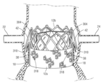
도 1은 자연 대동맥 판막의 단면도를 도시하고 있다.
도 2a는 자연 대동맥 판막 고리 내에 이식된 인공 심장 판막의 측면도를 도시하고 있다.
도 2b는 상행 대동맥으로부터 볼 때 도 2a의 이식된 인공 심장 판막을 도시하고 있다.
도 2c는 개시된 주제의 하나 이상의 실시예에 따른, 인공 심장 판막을 이식하기 위해 사용될 수 있는 예시적인 인공 판막 전달 장치를 도시하고 있다.
도 3a 내지 도 3c는 각각 제1 예에 따른 첨판 포획을 위한 인공 판막 위치설정, 팽창 및 장착 스테이지 동안의 단순화된 측면도를 도시하고 있다.
도 4a 내지 도 4d는 각각 제2 예에 따른 첨판 포획을 위한 카테터 위치설정, 첨판 관통, 봉합사 루프 형성 및 조임 스테이지의 단순화된 측면도를 도시하고 있다.
도 4e는 제2 예의 변형예에 따른, 활주 부재를 사용하는 조임 스테이지의 단순화된 측면도를 도시하고 있다.
도 4f는 제2 예에 따른 첨판 포획을 위한 봉합사 루프 로킹 스테이지의 단순화된 측면도를 도시하고 있다.
도 4g는 자연 첨판 중 하나 이상이 변형된 후 자연 대동맥 판막의 첨판 사이에 이식되는 인공 심장 판막의 단순화된 측면도를 도시하고 있다.
도 5a 내지 도 5h는 각각 제3 예에 따른 첨판 포획을 위한 제1 카테터 위치설정, 원위측 제1 앵커 형성, 근위측 제1 앵커 형성, 제2 카테터 위치설정, 원위측 제2 앵커 형성, 근위측 제2 앵커 형성, 커플링 부재 활주 및 로킹 스테이지의 단순화된 측면도를 도시하고 있다.
도 6a 및 도 6b는 각각 제4 예에 따른 개방 구성 및 폐쇄 구성에서의 액추에이터를 갖는 포획 디바이스를 도시하고 있다.
도 6c 내지 도 6e는 각각 제4 예에 따른 첨판 포획을 위한 포획 디바이스 위치설정, 첨판 개더링(gathering) 및 로킹 스테이지의 단순화된 측면도를 도시하고 있다.
도 7a는 제5 예에 따른 포획 디바이스를 도시하고 있다.
도 7b 내지 도 7d는 각각 제5 예에 따른 첨판 포획을 위한 카테터 위치설정, 포획 디바이스 부분 전개 및 포획 디바이스 완전 전개 스테이지의 단순화된 측면도를 도시하고 있다.
도 8a는 제6 예에 따른 첨판 절첩용 도구를 도시하고 있다.
도 8b는 스파이크를 있는 팁 구성을 채용하는 도 8a의 첨판 절첩 도구의 단순화된 상세도이다.
도 8c 내지 도 8d는 미늘이 있는 스파이크를 갖는 팁 구성을 채용하는 도 8a의 첨판 절첩 도구의 단순화된 상세도(각각 측면 및 저면)이다.
도 9a 내지 도 9f는 각각 제6 예에 따른 첨판 절첩을 위한 첨판 절첩 도구 위치설정, 첨판 맞물림, 단일 첨판의 원위 위치설정, 다수의 첨판의 원위 위치설정, 인공 심장 판막 위치설정 및 인공 심장 판막 팽창의 단순화된 측면도를 도시하고 있다.
도 10a 및 도 10b는 각각 제7 예에 따른 초기 구성 및 변형된 구성에서의 변형 가능한 포획 디바이스를 도시하고 있다.
도 10c는 제7 예에 따른 폐쇄 구성에서의 액추에이터를 갖는 변형 가능한 포획 디바이스를 도시하고 있다.
도 11a 내지 도 11e는 각각 제7 예에 따른 첨판 포획을 위한 포획 디바이스 위치설정, 첨판 맞물림, 첨판 개더링, 디바이스 변형 및 최종 로킹 스테이지의 단순화된 측면도를 도시하고 있다.1 shows a cross-sectional view of a natural aortic valve.
2A shows a side view of a prosthetic heart valve implanted within a natural aortic valve ring.
FIG. 2B shows the implanted prosthetic heart valve of FIG. 2A as viewed from the ascending aorta.
2C illustrates an exemplary prosthetic valve delivery device that can be used to implant a prosthetic heart valve, in accordance with one or more embodiments of the disclosed subject matter.
3A-3C respectively show simplified side views during prosthetic valve positioning, inflation and mounting stages for leaflet capture according to the first example.
4A-4D respectively show simplified side views of a catheter positioning, leaflet penetration, suture loop forming and tightening stage for leaflet capture according to a second example.
Figure 4e shows a simplified side view of a tightening stage using slide members, according to a variation of the second example.
4F shows a simplified side view of a suture loop locking stage for leaflet capture according to a second example.
4G depicts a simplified side view of a prosthetic heart valve implanted between the leaflets of a natural aortic valve after one or more of the natural leaflets have been deformed.
5A to 5H show first catheter positioning for leaflet capture, distal first anchor formation, proximal first anchor formation, second catheter positioning, distal second anchor formation, proximal second anchor formation, respectively, according to a third example. A simplified side view of the second anchor forming, coupling member sliding and locking stage is shown.
6a and 6b respectively show a capture device with an actuator in an open configuration and a closed configuration according to a fourth example.
6C-6E respectively show simplified side views of a capture device positioning, leaflet gathering and locking stage for leaflet capture according to a fourth example.
Fig. 7a shows a capture device according to a fifth example.
7B-7D show simplified side views of catheter positioning, capture device partial deployment and capture device full deployment stages, respectively, for leaflet capture according to a fifth example.
8A shows a tool for leaflet folding according to a sixth example.
FIG. 8B is a simplified detailed view of the leaflet folding tool of FIG. 8A employing a spiked tip configuration.
8C-8D are simplified detailed views (side and bottom views, respectively) of the leaflet folding tool of FIG. 8A employing a tip configuration with barbed spikes.
9A-9F show leaflet folding tool positioning, leaflet engagement, distal positioning of a single leaflet, distal positioning of multiple leaflets, prosthetic heart valve positioning and prosthetic heart valve inflation, respectively, according to a sixth example. A simplified side view of is shown.
10a and 10b respectively show the deformable capture device in an initial configuration and a modified configuration according to a seventh example.
10c shows a deformable capture device with an actuator in a closed configuration according to a seventh example.
11A-11E respectively show simplified side views of capture device positioning, leaflet engagement, leaflet gathering, device deformation and final locking stages for leaflet capture according to a seventh example.
일반적인 고려사항General Considerations
이 설명의 목적으로, 본 개시내용의 실시예의 특정 양태, 장점, 및 신규한 특징이 본 명세서에 설명된다. 개시된 방법, 장치, 및 시스템은 임의의 방식으로 한정으로서 해석되어서는 안된다. 대신에, 본 개시내용은 단독으로 그리고 서로 다양한 조합 및 서브조합으로, 다양한 개시된 실시예의 모든 신규한 및 자명하지 않은 특징 및 양태에 관한 것이다. 방법, 장치, 및 시스템은 임의의 특정 양태 또는 특징 또는 이들의 조합에 한정되는 것은 아니고, 또한 개시된 실시예는 임의의 하나 이상의 특정 장점이 존재하거나 문제가 해결되는 것을 요구하는 것도 아니다. 임의의 예로부터의 기술은 다른 예들 중 임의의 하나 이상에 설명된 기술과 조합될 수 있다.For purposes of this description, certain aspects, advantages, and novel features of embodiments of the present disclosure are described herein. The disclosed methods, devices, and systems should not be construed as limiting in any way. Instead, the present disclosure is directed to all novel and non-obvious features and aspects of the various disclosed embodiments, alone and in various combinations and subcombinations with each other. The methods, apparatus, and systems are not limited to any particular aspect or feature or combination thereof, nor does the disclosed embodiment require that any one or more particular advantage or problem be solved. A technique from any example may be combined with a technique described in any one or more of the other examples.
개시된 실시예의 일부의 동작은 편리한 제시를 위해 특정 순차적인 순서로 설명되었지만, 특정 순서화가 이하에 설명된 특정 언어에 의해 요구되지 않으면, 이 설명의 방식은 재배열을 포함한다는 것이 이해되어야 한다. 예를 들어, 순차적으로 설명된 동작은 몇몇 경우에 재배열되거나 또는 동시에 수행될 수도 있다. 더욱이, 간단화를 위해, 첨부 도면은 개시된 방법이 다른 방법과 함께 사용될 수 있는 다양한 방식을 도시하지 않을 수도 있다. 부가적으로, 설명은 때때로 개시된 방법을 설명하기 위해 "제공" 또는 "달성"과 같은 용어를 사용한다. 이들 용어는 수행되는 실제 동작의 고레벨 추상 개념이다. 이들 용어에 대응하는 실제 동작은 특정 구현예에 따라 다양할 수도 있고, 통상의 기술자에 의해 즉시 인식 가능하다.Although the operations of some of the disclosed embodiments have been described in a specific sequential order for convenient presentation, it should be understood that this manner of description includes a rearrangement unless a specific ordering is required by specific language described below. For example, operations described sequentially may be rearranged or performed concurrently in some cases. Moreover, for simplicity, the accompanying drawings may not depict the various ways in which the disclosed methods may be used with other methods. Additionally, the description sometimes uses terms such as "providing" or "achieve" to describe the disclosed method. These terms are high-level abstractions of the actual operations being performed. The actual actions corresponding to these terms may vary depending on the particular implementation, and are immediately recognizable to those skilled in the art.
본 명세서에 사용될 때, 인공 심장 판막 조립체 및 인공 심장 판막의 이식 및 구조체와 관련하여, "근위"는 환자의 외부에 있는 전달 시스템 또는 장치의 핸들 및 사용자에 더 가까운 위치, 방향 또는 구성요소의 부분을 칭하고, 반면 "원위"는 핸들 및 사용자로부터 더 멀리 이격되어 있고 이식 부위에 더 가까운 위치, 방향 또는 구성요소의 부분을 칭한다. 용어 "종방향" 및 "축방향"은 달리 명시적으로 정의되지 않으면, 근위 및 원위 방향으로 연장하는 축을 칭한다.As used herein, with reference to prosthetic heart valve assemblies and implantation and construction of prosthetic heart valves, "proximal" refers to the handle of a delivery system or device that is external to the patient and the portion of the component that is positioned, oriented, or closer to the user. , whereas "distal" refers to a location, orientation, or portion of a component that is further away from the handle and user and closer to the implantation site. The terms "longitudinal" and "axial", unless explicitly defined otherwise, refer to an axis extending in proximal and distal directions.
용어 "축방향", "반경방향" 및 "원주방향"은 본 명세서에서 인공 심장 판막의 프레임의 기하학 형상에 대한 구성요소의 배열 및 조립을 설명하기 위해 사용되었다. 이러한 용어들은 편리한 설명을 위해 사용되었지만, 개시된 실시예는 설명에 엄격히 한정되는 것은 아니다. 특히, 구성요소 또는 작용이 특정 방향에 대해 설명되는 경우, 지정된 방향에 평행한 방향 뿐만 아니라 그로부터 약간의 편차가 포함된다. 따라서, 프레임의 축방향을 따라 연장하는 구성요소의 설명은 구성요소가 프레임의 중심과 정렬될 것을 요구하지 않고; 오히려, 구성요소는 실질적으로 프레임의 중심축에 평행한 방향을 따라 연장될 수 있다.The terms “axial,” “radial,” and “circumferential” are used herein to describe the arrangement and assembly of components relative to the geometry of the frame of a prosthetic heart valve. Although these terms are used for convenient description, the disclosed embodiments are not strictly limited to the description. In particular, where a component or action is described with respect to a particular direction, directions parallel to the specified direction as well as slight deviations therefrom are included. Thus, a description of a component extending along the axial direction of the frame does not require the component to be aligned with the center of the frame; Rather, the component may extend along a direction substantially parallel to the central axis of the frame.
본 명세서에 사용될 때, 용어 "일체로 형성된" 및 "단일 구성"은 재료의 개별적으로 형성된 부품을 서로 고정하기 위한 임의의 용접부, 체결구, 또는 다른 수단을 포함하지 않는 구성을 칭한다.As used herein, the terms "integrally formed" and "unitary construction" refer to construction that does not include any welds, fasteners, or other means for securing the individually formed parts of material together.
본 명세서에 사용될 때, "동시에" 또는 "일제히" 발생하는 동작은 일반적으로 서로 동일 시간에 발생하지만, 예를 들어, 구성요소들 사이의 간격에 기인하여 다른 것에 대한 동작의 발생에 있어서 지연이 특정 대조적인 언어의 부재시에, 상기 용어의 범주 내에 명시적으로 있다.As used herein, actions that occur "simultaneously" or "simultaneously" generally occur at the same time as each other, but a delay in the occurrence of an action relative to another is specified, for example, due to spacing between components. In the absence of contrasting language, it is expressly within the scope of the term.
본 명세서 및 청구범위에 사용될 때, 단수 형태는 문맥상 명백히 달리 지시되지 않으면, 복수 형태를 포함한다. 부가적으로, 용어 "구비한다"는 "포함한다"를 의미한다. 또한, 용어 "커플링된"은 일반적으로 물리적으로, 기계적으로, 화학적으로, 자기적으로, 그리고/또는 전기적으로 커플링되거나 연결된 것을 의미하고, 특정 대조적인 용어의 부재시에 커플링된 또는 연계된 아이템 사이의 중간 요소의 존재를 배제하는 것은 아니다. 본 명세서에 사용될 때, "및/또는"은 "및" 또는 "또는", 뿐만 아니라 "및" 및 "또는"을 의미한다.As used in this specification and claims, the singular forms include the plural forms unless the context clearly dictates otherwise. Additionally, the term “comprises” means “comprises”. Also, the term "coupled" means coupled or connected generally physically, mechanically, chemically, magnetically, and/or electrically, and in the absence of a specific contrasting term coupled or associated It does not preclude the presence of intermediate elements between items. As used herein, “and/or” means “and” or “or” as well as “and” and “or”.
방향 및 다른 상대 참조가 본 명세서의 도면 및 원리의 설명을 용이하게 하기 위해 사용될 수도 있지만, 한정되도록 의도된 것은 아니다. 예를 들어, "내부", "외부", "상부", "외부", "내측", "외측", "상", "하", "내", "외", "좌", "우" 등과 같은 특정 용어가 사용될 수도 있다. 이러한 용어는 적용 가능한 경우, 특히 예시된 예에 관하여, 상대 관계를 다룰 때 몇몇 명확한 설명을 제공하기 위해 사용된다. 그러나, 이러한 용어는 절대적인 관계, 위치, 및/또는 배향을 암시하도록 의도된 것은 아니다. 예를 들어, 물체와 관련하여, "상부" 부분은 단순히 물체를 뒤집음으로써 "하부" 부분이 될 수 있다. 그럼에도 불구하고, 이는 여전히 동일한 부분이고, 물체는 동일하게 남아 있다.Directions and other relative references may be used to facilitate the description of the figures and principles herein, but are not intended to be limiting. For example, "inside", "outside", "top", "outside", "inside", "outside", "top", "bottom", "inside", "outside", "left", "rightside" ", etc. may also be used. These terms, where applicable, are used to provide some clarification when dealing with relative relationships, especially with respect to the illustrated examples. However, these terms are not intended to imply an absolute relationship, position, and/or orientation. For example, with respect to an object, an “upper” portion can become a “lower” portion simply by turning the object over. Nevertheless, it is still the same part, and the object remains the same.
수치 범위의 개시내용은 달리 언급되지 않으면, 종단점을 포함하여, 범위 내의 각각의 이산 지점을 언급하는 것으로서 이해되어야 한다. 달리 지시되지 않으면, 명세서 또는 청구범위에 사용된 바와 같은, 성분의 양, 분자량, 백분율, 온도, 시간 등의 양을 표현하는 모든 수치는 용어 "약"에 의해 수식되는 것으로서 이해되어야 한다. 이에 따라, 암시적으로 또는 명시적으로 달리 지시되지 않으면, 또는 문맥이 더 한정적인 구성을 갖는 것으로 통상의 기술자에 의해 적절하게 이해되지 않으면, 설명된 수치 파라미터는 통상의 기술자에게 알려진 바와 같이, 표준 시험 조건/방법 하에서 추구되는 요구된 특성 및/또는 검출 한계에 의존할 수도 있는 근사치이다. 실시예를 설명된 종래 기술과 직접적이고 명시적으로 구별할 때, 단어 "약"이 언급되지 않으면 실시예 수치는 근사치가 아니다. "실질적으로", "대략", "약" 또는 유사한 언어가 특정 값과 조합하여 명시적으로 사용될 때마다, 달리 명시적으로 언급되지 않으면, 해당 값의 최대 10%까지의 변형이 의도된다.The disclosure of numerical ranges is to be understood as referring to each discrete point within the range, inclusive of the endpoints, unless otherwise stated. Unless otherwise indicated, as used in the specification or claims, all numbers expressing quantities, such as amounts of ingredients, molecular weights, percentages, temperatures, times, etc., are to be understood as being modified by the term "about." Accordingly, unless indicated otherwise, either implicitly or explicitly, or unless the context is properly understood by those skilled in the art to have a more restrictive configuration, the numerical parameters described are standard, as known to those skilled in the art. It is an approximation that may depend on the desired properties and/or limits of detection sought under test conditions/methods. When directly and explicitly distinguishing the examples from the described prior art, the example figures are not approximations unless the word "about" is mentioned. Whenever "substantially", "approximately", "about" or similar language is used expressly in combination with a particular value, a variation of up to 10% of that value is intended, unless expressly stated otherwise.
개시된 기술의 개요Overview of the Disclosed Technology
심장 판막(예를 들어, 자연 심장 판막 또는 이전에 이식된 인공 심장 판막)의 첨판을 절첩 및/또는 포획하기 위한 방법 및 도구가 본 명세서에 설명된다. 몇몇 실시예에서, 심장 판막은 대동맥 위치에 있고 절첩/포획은 관상 동맥으로의 혈액 유동을 폐색하는 것을 회피하거나 적어도 위험을 감소시키는 데 효과적이다. 몇몇 실시예에서, 첨판의 부분(또는 첨판들의 부분들)은 기존 판막 구조체(예를 들어, 자연 심장 판막 또는 이전에 이식된 인공 심장 판막) 내의 그 설치 중에 인공 심장 판막의 하나 이상의 외부 특징부에 의해 관상 소공(의 상류)의 원위측에 포획되어 유지된다. 대안적으로 또는 부가적으로, 첨판의 부분(또는 첨판들의 부분들)은 자체로 절첩되고 하나 이상의 봉합사, 커플링 부재 및/또는 포획 디바이스(예를 들어, 로킹 디바이스, 클립 부재, 하강 바아, 파지 부재)에 의해 관상 소공(의 상류)의 원위측에 유지된다. 새로운 인공 심장 판막이 이후에 기존 판막 구조체 내에 설치될 때, 기존 판막 구조체의 포획 및/또는 절첩된 첨판이 관상 동맥 소공의 원위측의 장소에 배치되어, 이에 의해 혈액이 관상 동맥으로 폐색되지 않고 유동할 수 있게 한다. 다른 실시예에서, 심장 판막은 대동맥 위치 이외의 위치, 예를 들어 폐, 삼첨판 또는 승모판 위치에 있다.Methods and tools for folding and/or capturing leaflets of a heart valve (eg, a natural heart valve or a previously implanted prosthetic heart valve) are described herein. In some embodiments, the heart valve is in an aortic location and folding/capture is effective to avoid or at least reduce the risk of obstructing blood flow to the coronary arteries. In some embodiments, a portion of a leaflet (or portions of leaflets) attaches to one or more external features of a prosthetic heart valve during its installation within an existing valve structure (eg, a natural heart valve or a previously implanted artificial heart valve). It is captured and retained on the distal side of (upstream of) the tubular ostium by Alternatively or additionally, a portion of the leaflet (or portions of the leaflets) may fold over itself and may be provided with one or more sutures, coupling members, and/or capture devices (e.g., locking devices, clip members, drop bars, gripping devices). member) on the distal side of (upstream of) the tubular ostium. When a new prosthetic heart valve is subsequently installed within the existing valve structure, the captured and/or folded leaflet of the existing valve structure is placed in a distal location of the coronary foramen, thereby allowing blood to flow unoccluded into the coronary artery. allow you to do In other embodiments, the heart valve is at a location other than the aorta location, such as at a pulmonary, tricuspid or mitral valve location.
개시된 기술의 예Examples of Disclosed Technology
도 1은 상행 대동맥(20)으로부터 좌심실(26)을 분리하는 복수의 첨판(38)(예를 들어, 3개의 첨판, 도 1의 단순화된 도면에는 단지 2개만이 도시되어 있음)을 갖는 자연 판막 구조체의 대동맥 근부의 해부학 구조를 도시하고 있다. 도 2a 및 도 2b는 자연 판막 구조체의 대동맥 고리(18) 내에 이식된 예시적인 인공 심장 판막(10)을 도시하고 있다. 인공 심장 판막(10)은 환자 내에 전달을 위한 압축 구성과 장착을 위한 팽창 구성(예를 들어, 도 2a에 도시되어 있는 바와 같이) 사이에서 반경방향으로 압축 가능/팽창 가능할 수 있다.1 is a natural valve with a plurality of leaflets 38 (e.g., three leaflets, only two are shown in the simplified view of FIG. 1) separating the
인공 심장 판막(10)은 환형 스텐트 또는 프레임(12)을 포함할 수 있다. 프레임(12) 또는 그 구성요소(예를 들어, 지주 및/또는 체결구)는 관련 기술 분야에 공지되어 있는 바와 같은, 임의의 다양한 적합한 소성-팽창 가능 재료(예를 들어, 스테인리스 강 등) 또는 자기-팽창 재료(예를 들어, 니티놀과 같은 니켈 티타늄 합금(NiTi))로 제조될 수 있다. 프레임(12)을 형성하는 데 사용될 수 있는 적합한 소성-팽창 가능 재료는 스테인리스 강, 생체적합성 고강도 합금(예를 들어, 코발트-크롬 또는 니켈-코발트-크롬 합금), 폴리머 또는 이들의 조합을 비한정적으로 포함한다. 특정 실시예에서, 프레임(12)은 UNS R30035 합금(ASTM F562-02에 의해 커버됨)과 동등한 MP35N® 합금(미국 팬실배니아주 젠킨타운 소재의 SPS Technologies)과 같은 니켈-코발트-크롬-몰리브덴 합금으로 제조된다. MP35N® 합금/UNS R30035 합금은 중량%로 35% 니켈, 35% 코발트, 20% 크롬 및 10% 몰리브덴을 포함한다.The
소성-팽창 가능 재료로 구성될 때, 프레임(12)(및 따라서 인공 판막(10))은 전달 카테터 상에서 반경방향 접힘 구성으로 크림핑되고, 이어서 팽창 가능한 벌룬 또는 동등한 팽창 메커니즘에 의해 환자 내부에서 팽창될 수 있다. 자기-팽창 가능 재료로 구성될 때, 프레임(12)(및 따라서 인공 판막(10))은 반경방향 접힘 구성으로 크림핑되고 전달 카테터의 외장(sheath) 또는 동등한 메커니즘 내로 삽입에 의해 접힘 구성으로 구속될 수 있다. 일단 신체 내부에 있으면, 인공 판막은 전달 외장으로부터 전진될 수 있는데, 이는 인공 판막이 그 기능 크기로 팽창될 수 있게 한다.When constructed of a plastically-expandable material, the frame 12 (and therefore the prosthetic valve 10) is crimped onto the delivery catheter into a radially collapsed configuration and then inflated inside the patient by an inflatable balloon or equivalent inflation mechanism. It can be. When constructed from a self-expandable material, frame 12 (and therefore prosthetic valve 10) is crimped into a radially folded configuration and constrained into a collapsed configuration by insertion into a sheath or equivalent mechanism of a delivery catheter. It can be. Once inside the body, the prosthetic valve can be advanced from the delivery sheath, which allows the prosthetic valve to inflate to its functional size.
도 2c는 본 명세서에 설명된 인공 심장 판막(10) 또는 임의의 다른 인공 심장 판막과 같은 인공 심장 판막을 전달하도록 구성된 예시적인 전달 장치(200)를 도시하고 있다. 인공 판막(10)은 예로서 인공 판막(10)의 팽창 및 로킹 메커니즘의 원위 부재와 전달 장치(200)의 작동 조립체의 제2 작동 부재 사이의 제거 가능한 커플링을 통해 전달 장치(200)에 해제 가능하게 커플링될 수 있다. 인공 판막(10)은 원위 단부(224) 및 근위 단부(226)를 포함할 수 있고, 근위 단부(226)는 원위 단부(224)보다 전달 장치(200)의 핸들(204)에 더 가깝게 위치되고, 원위 단부(224)는 근위 단부(226)보다 핸들(204)로부터 더 멀리 위치된다. 전달 장치(200)는 스텐트 또는 이식편과 같은, 인공 판막 이외의 인공 디바이스를 이식하는데 사용될 수 있다는 것이 이해되어야 한다.2C depicts an exemplary delivery device 200 configured to deliver a prosthetic heart valve, such as
예시된 예에서 전달 장치(200)는 일반적으로 핸들(204), 핸들(204)로부터 원위측으로 연장하는 제1 세장형 샤프트(206)(예시된 실시예에서 외부 샤프트를 포함함), 외부 샤프트(206)를 통해 원위측으로 연장하는 적어도 하나의 액추에이터 조립체(208)를 포함한다. 몇몇 예에서, 샤프트(206)의 원위 단부 부분(216)은 환자의 혈관 구조를 통한 인공 판막의 전달 중에 그 반경방향으로 압축된 전달 상태로 인공 판막을 수용하도록 크기 설정될 수 있다. 이 방식으로, 원위 단부 부분(216)은 전달 중에 인공 판막을 위한 전달 외장 또는 캡슐로서 기능한다.The delivery device 200 in the illustrated example generally includes a
적어도 하나의 액추에이터 조립체(208)는 작동될 때 인공 판막(10)을 반경방향으로 팽창 및/또는 반경방향으로 접도록 구성될 수 있고, 인공 심장 판막(10)에 제거 가능하게 커플링될 수도 있다. 예시된 예는 예시를 위해 2개의 액추에이터 조립체(208)를 도시하고 있지만, 하나의 액추에이터(208)가 인공 판막의 각각의 액추에이터에 제공될 수 있다는 것이 이해되어야 한다. 예를 들어, 3개의 액추에이터 조립체(208)가 3개의 액추에이터를 갖는 인공 판막을 위해 제공될 수 있다. 다른 예에서, 더 많거나 더 적은 수의 액추에이터 조립체가 존재할 수 있다. 액추에이터 조립체(208)는 인공 판막(10)에 해제 가능하게 커플링될 수 있다. 예를 들어, 각각의 액추에이터 조립체(208)는 인공 판막(10)의 각각의 액추에이터에 커플링될 수 있다. 각각의 액추에이터 조립체(208)는 지지 튜브 또는 슬리브 및 액추에이터 부재를 포함할 수 있다. 몇몇 예에서, 액추에이터 조립체(208)는 또한 로킹 도구를 포함할 수 있다. 작동될 때, 액추에이터 조립체는 인공 판막을 반경방향으로 팽창 및 접기 위해 인공 판막의 부분에 압박력 및/또는 견인력을 전달할 수 있다. 액추에이터 조립체(208)는 외부 샤프트(206)의 하나 이상의 루멘 내에 적어도 부분적으로 반경방향으로 배치되고, 그를 통해 축방향으로 연장할 수 있다. 예를 들어, 액추에이터 조립체(208)는 샤프트(206)의 중앙 루멘을 통해 또는 샤프트(206) 내에 형성된 개별의 각각의 루멘을 통해 연장할 수 있다.The at least one
전달 장치(200)의 핸들(204)은 인공 판막(10)을 팽창 및/또는 전개하기 위해 전달 장치(200)의 상이한 구성요소를 제어하기 위한 하나 이상의 제어 메커니즘(예를 들어, 노브 또는 다른 작동 메커니즘)을 포함할 수 있다. 예를 들어, 도 2c에서, 핸들(204)은 제1, 제2 및 제3 노브(210, 212, 214)를 포함한다. 제1 노브(210)는, 일단 인공 판막이 환자의 신체와 함께 원하는 이식 장소에 있는 장소 또는 인접한 장소로 전진되었으면, 전달 외장(216)으로부터 인공 판막을 전개시키기 위해 원위 및/또는 근위 방향으로 인공 판막(10)에 대한 외부 샤프트(206)의 축방향 이동을 생성하도록 구성된 회전 가능 노브일 수 있다. 예를 들어, 제1 방향(예를 들어, 시계 방향)으로의 제1 노브(210)의 회전은 인공 판막(10)에 대해 근위측으로 외장(216)을 후퇴시킬 수 있고 제2 방향(예를 들어, 반시계 방향)으로의 제1 노브(210)의 회전은 외장(216)을 원위측으로 전진시킬 수 있다. 다른 예에서, 제1 노브(210)는 노브를 견인 및/또는 압박하는 것과 같이, 노브(210)를 축방향으로 활주 또는 이동시킴으로써 작동될 수 있다. 다른 예에서, 제1 노브(210)의 작동(노브(210)의 회전 또는 활주 이동)은 전달 외장(216)에 대한 액추에이터 조립체(208)(따라서 인공 판막(10))의 축방향 이동을 생성하여 인공 판막을 외장(216)으로부터 원위측으로 전진시킬 수 있다.Handle 204 of delivery device 200 may include one or more control mechanisms (e.g., knobs or other actuations) for controlling different components of delivery device 200 to inflate and/or deploy
제2 노브(212)는 인공 판막(10)의 반경방향 팽창 및/또는 수축을 생성하도록 구성된 회전 가능 노브일 수 있다. 예를 들어, 제2 노브(212)의 회전은 액추에이터 부재와 지지 튜브를 서로에 대해 축방향으로 이동시킬 수 있다. 제1 방향(예를 들어, 시계 방향)으로의 제2 노브(212)의 회전은 인공 판막(10)을 반경방향으로 팽창시킬 수 있고 제2 방향(예를 들어, 반시계 방향)으로의 제2 노브(212)의 회전은 인공 판막(10)을 반경방향으로 접을 수 있다. 다른 예에서, 제2 노브(212)는 노브를 견인하고 및/또는 압박하는 것과 같이, 노브(212)를 축방향으로 활주 또는 이동시킴으로써 작동될 수 있다.The
제3 노브(214)는 인공 심장 판막(10)을 그 팽창 구성으로 유지하도록 구성된 회전 가능 노브일 수 있다. 예를 들어, 제3 노브(214)는 각각의 액추에이터 조립체(208)의 로킹 도구의 근위 단부 부분에 동작식으로 연결될 수 있다. 제1 방향(예를 들어, 시계 방향)으로의 제3 노브의 회전은 인공 판막의 프레임의 반경방향 압축에 저항하기 위해 로킹 너트를 그 원위 위치로 전진시키도록 각각의 로킹 도구를 회전시킬 수 있다. 반대 방향(예를 들어, 반시계 방향)으로의 노브(214)의 회전은 각각의 로킹 도구를 인공 판막(10)으로부터 디커플링하기 위해 반대 방향으로 각각의 로킹 도구를 회전시킬 수 있다. 다른 실시예에서, 제3 노브(214)는 노브를 견인 및/또는 압박하는 것과 같이 제3 노브(214)를 축방향으로 활주 또는 이동시킴으로써 작동될 수 있다.
도시되어 있지 않지만, 몇몇 예에서, 핸들(204)은 각각의 액추에이터 부재의 근위 단부 부분에 동작식으로 연결된 제4 회전 가능 노브를 포함할 수 있다. 제4 노브는 각각의 액추에이터의 근위 부분으로부터 각각의 액추에이터 부재를 나사 풀림하기 위해, 노브의 회전시, 각각의 액추에이터 부재를 회전시키도록 구성될 수 있다. 일단 로킹 도구와 액추에이터 부재가 인공 판막(10)에서 언커플링되면, 이들은 환자로부터 제거될 수 있다. 인공 심장 판막을 전달 및 이식하기 위한 전달 장치의 구성 및 동작에 관한 추가 상세는 미국 특허 제8,652,202호, 제9,339,384호, 제9,827,093호, 제9,867,700호, 제10,076,638호 및 제10,806,573호에서 발견될 수 있고, 이들 모두는 본 명세서에 참조로서 합체되어 있다.Although not shown, in some examples, handle 204 may include a fourth rotatable knob operatively connected to a proximal end portion of each actuator member. The fourth knob may be configured to rotate each actuator member upon rotation of the knob to unscrew each actuator member from a proximal portion of each actuator. Once the locking tool and actuator member are uncoupled from the
몇몇 실시예에서, 프레임(12)의 지주는 프레임(12)의 반경방향 팽창 및 수축을 허용하도록 서로에 대해 피봇 가능하거나 굴곡 가능할 수 있다. 예를 들어, 프레임(12)은 재료의 단일편(예를 들어, 금속 튜브)으로부터 형성될 수 있다(예를 들어, 레이저 절단, 전주 도금 또는 물리적 기상 증착을 통해). 다른 실시예에서, 프레임(12)은 개별 구성요소(예를 들어, 프레임의 지주 및 체결구)를 형성하고 이어서 개별 구성요소를 함께 기계적으로 조립 및 연결함으로써 구성될 수 있다.In some embodiments, the posts of
프레임(12) 및 인공 심장 판막(10)의 구성에 관한 추가의 상세는 미국 특허 출원 공개 제2012/0123529호, 제2018/0153689호, 제2018/0344456호, 제2019/0060057호, 제2019/0365530호, 제2020/0188099호 및 제2020/0390547호, 및 국제 출원 공개 WO-2020/081893 및 WO-2021/003167에 설명되어 있고, 이들 모두는 본 명세서에 참조로서 합체되어 있다.Additional details concerning the construction of
프레임(12)은 제1 축방향 단부 및 제2 축방향 단부를 가질 수 있다. 도시되어 있는 실시예에서, 제1 축방향 단부(예를 들어, 동관 연결부 레벨(32) 부근에서 상행 대동맥(20)을 향함)는 유출 단부일 수 있고, 제2 축방향 단부(예를 들어, 대동맥 고리(18) 부근에서 좌심실(26)을 향함)는 유입 단부일 수 있다. 몇몇 실시예에서, 유출 단부는 인공 판막을 이식 부위로 전달하기 위한 전달 장치에 커플링될 수 있다. 대안적으로, 인공 판막(10)은 이식 부위로의 전달을 위해 전달 장치의 팽창 가능 벌룬 상에 반경방향으로 크림핑될 수 있다. 자연 대동맥 판막 내에 인공 심장 판막(10)을 이식하는 것은 경대퇴 역행 전달 접근법을 통해 이루어질 수 있다. 따라서, 인공 심장 판막의 전달 구성에서, 유출 단부는 인공 판막의 최근위 단부이다. 다른 실시예에서, 유입 단부는 치환되는 특정 자연 판막 및 사용되는 전달 기술(예를 들어, 경중격, 경심첨부 등)에 따라, 전달 구성에서 인공 심장 판막의 최근위 단부일 수 있다. 몇몇 경우에, 유입 단부는 전달 구성에서 전달 장치에 커플링될 수 있다.
인공 판막(10)은 일 방향으로 프레임(12)을 통한 혈액 유동을 허용하기 위해 구성된 판막 구조체를 또한 포함한다. 판막 구조체는 유입 단부로부터 유출 단부로 인공 심장 판막(10)을 통한 혈액의 유동을 조절하도록 구성될 수 있다. 판막 구조체는 예를 들어, 가요성 재료로 제조된 하나 이상의 첨판(14)(도 2a 및 도 2b에 도시되어 있는 3개의 첨판)에 의해 형성된 첨판 조립체를 포함할 수 있다. 인접한 첨판(14)은 프레임(12)의 각각의 부분에 커플링되어(직접 또는 간접적으로), 이에 의해 첨판 조립체의 적어도 일부를 프레임(12)에 고정시키는 맞교차부(36)를 형성하도록 함께 배열될 수 있다. 첨판(14)은 전체적으로 또는 부분적으로, 생물학적 재료, 생체적합성 합성 재료, 또는 다른 이러한 재료로부터 제조될 수 있다. 적합한 생물학적 재료는 예를 들어 소의 심막(또는 다른 소스로부터의 심막)을 포함할 수 있다. 판막 구조체가 인공 심장 판막(10)의 프레임(12)에 커플링될 수 있는 방식을 포함하여, 경도관 인공 심장 판막에 관한 추가의 상세는 예를 들어, 미국 특허 제6,730,118호, 제7,393,360호, 제7,510,575호, 제7,993,394호, 및 제8,652,202호, 및 미국 특허 출원 공개 제2012/0123529호, 제2018/0325665호, 및 제2019/0365530호에서 발견될 수 있고, 이들 모두는 본 명세서에 그대로 참조로서 합체되어 있다.
인공 심장 판막(10)은 하나 이상의 스커트 또는 밀봉 부재를 또한 포함할 수 있다. 예를 들어, 인공 심장 판막(10)은 프레임(12)의 내부면(도 2a 및 도 2b에 도시되어 있지 않음) 상에 장착된 내부 스커트 및/또는 프레임(12)의 외부면 상에 장착된 외부 스커트(16)를 포함할 수 있다. 내부 스커트는 프레임(12)의 내부면의 전체 원주에 걸쳐 있는 원주방향 내부 스커트일 수 있다. 내부 스커트는 판막 주위 누출을 방지하거나 감소시키기 위한 밀봉 부재로서(예를 들어, 판막이 이식 부위에 배치될 때) 그리고 프레임(12)에 첨판(14)의 부분을 고정하기 위한 부착 표면으로서 기능할 수 있다. 외부 스커트(16)는 자연 판막 고리(18)의 조직에 대해 밀봉하고 인공 판막(10)을 지나는 판막 주위 누출을 감소시키는 것을 도와줌으로써 밀봉 부재로서 기능할 수 있다. 내부 및 외부 스커트는 임의의 다양한 합성 재료(예를 들어, 폴리에틸렌 테레프탈레이트(PET)) 또는 자연 조직(예를 들어, 심막 조직)을 포함하는 임의의 다양한 적합한 생체적합성 재료로부터 형성될 수 있다. 내부 및 외부 스커트는 봉합사, 접착제, 용접 및/또는 프레임에 스커트를 부착하기 위한 다른 수단을 사용하여 프레임에 장착될 수 있다. 내부 및 외부 스커트에 관한 추가 상세 및 첨판을 내부 스커트에 조립하고 프레임 상에 스커트를 조립하기 위한 기술은 미국 특허 출원 공개 제2012/0123529호, 제2019/0192296호 및 제2019/0365530호, 및 국제 출원 공개 WO-2020/159783 및 WO-2020/198273에 개시되어 있고, 이들 모두는 본 명세서에 참조로서 합체되어 있다.
기존 이식된 인공 판막의 경우, 판막 구조체는 시간 경과에 따라 자연적으로 열화될 수도 있어 이에 의해 적절한 심장 기능을 유지하기 위해 복구 또는 치환을 필요로 한다. 판막 내(ViV) 시술에서, 새로운 인공 심장 판막이 적절한 기능을 복원하기 위해 기존의 열화하는 인공 심장 판막 내에 장착된다. 그러나, ViV 시술은 관상 동맥(22, 24)의 폐색의 증가된 위험을 제기할 수도 있다. 특히, 기존 인공 심장 판막의 판막 구조체 내에 새로운 인공 심장 판막의 장착은 기존 심장 판막의 첨판을 외향으로 변위시켜, 이에 의해 관상 동맥(22, 24)의 소공을 폐색할 수 있다. 더욱이, 기존 심장 판막의 첨판은 새로운 인공 판막의 프레임 외부에 배치되기 때문에, 이들은 프레임의 외부면을 커버하여, 이에 의해 프레임(12)의 개구(34)를 폐색하는 실질적으로 불투과성 관형 구조를 생성할 수도 있다. 몇몇 환자 해부학 구조(예를 들어, 판막(10)의 유출이 동관(STJ) 레벨(32)에 있고 판막(10)의 직경이 STJ 직경과 유사하여 프레임(12)이 STJ 레벨(32)에서 대동맥 벽(30)에 닿거나 매우 근접할 때)에서, 기존 판막 구조체의 첨판은 관상 동맥(22, 24)으로의 향후 접근 또는 심장 주기의 확장기 단계 동안 판막 프레임(12)을 통해 관상 동맥(22, 24)으로의 관류 능력을 손상시킬 수도 있다. 인공 심장 판막(10)이 자연 판막 내에서 경피적으로 팽창되어, 자연 첨판(38)이 관상 소공을 향해 외향으로 변위될 때 일부 환자 해부학 구조에서 유사한 문제가 발생할 수도 있다.In the case of conventionally implanted prosthetic valves, the valve structure may naturally degrade over time, thereby requiring repair or replacement to maintain proper cardiac function. In an intravalvular (ViV) procedure, a new prosthetic heart valve is placed within an existing deteriorating prosthetic heart valve to restore proper function. However, the ViV procedure may pose an increased risk of occlusion of the
관상 동맥(22, 24)으로의 혈액 유동의 폐색을 회피하기 위해, 기존 심장 판막(자연 대동맥 판막이든 이전에 이식된 인공 판막이든)의 첨판은 기존 판막 구조체 내의 새로운 인공 심장 판막의 이식 전 또는 중에 포획 및/또는 절첩될 수 있다. 몇몇 실시예에서, 새로운 인공 심장 판막은 판막 프레임의 외부에 하나 이상의 구성요소를 포함할 수 있다. 구성요소는 인공 심장 판막이 설치될 때 관상 동맥의 레벨로부터 이격하여 기존 판막 구조체의 첨판 중 하나, 일부 또는 모두를 포획하고 위치설정하여, 이에 의해 동맥에 대한 혈관 접근을 유지하도록 설계될 수 있다.To avoid obstruction of blood flow to the
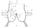
예를 들어, 도 3a 내지 도 3c는 기존 판막 구조체(예를 들어, 도시되어 있는 예에서 자연 심장 판막, 또는 도시되어 있지 않은 예에서 이전에 이식된 인공 심장 판막)의 하나 이상의 첨판(38)을 재위치설정하기 위한 첨판 포획 부재(304)를 포함하는 인공 심장 판막(10)을 도시하고 있다. 첨판 포획 부재(304)는 예를 들어 근위 단부의 부착부(306)를 통해 및 원위 단부의 부착부(308)를 통해 인공 심장 판막(10)의 프레임(12)에 부착될 수 있다. 예를 들어, 부착부(306, 308)는 각각의 포획 부재(304)와 프레임(12)의 대응 부분 사이에서 연장하는 봉합사, 강성 부착 부재(예를 들어, 브래킷 또는 체결구), 및/또는 커플링 재료(예를 들어, 용접부, 접착제 또는 에폭시)를 포함할 수 있다. 첨판 포획 부재(304)는 그렇지 않으면 부착부(306, 308) 사이에서 판막 프레임(12)에 독립적으로 자유롭게 이동할 수도 있다.For example, FIGS. 3A-3C illustrate one or
개시된 실시예의 설명에서, 자연 대동맥 판막에 대한 역행 전달 접근법을 사용하는 맥락에서 방법 및 디바이스가 설명된다. 이와 같이, 인공 판막(또는 다른 디바이스) 또는 그 구성요소의 "근위 단부"라는 용어는 그 유출 단부를 칭하는 데 사용되고 인공 판막(또는 다른 디바이스) 또는 그 구성요소의 "원위 단부"라는 용어는 그 유입 단부를 칭하는 데 사용된다. 그러나, 대동맥 판막과 반대 방향으로 전달되면(예를 들어, 경심첨부로), 전달 중에 인공 판막의 유출 단부는 원위 단부일 것이고 인공 판막의 유입 단부는 근위 단부일 것이라는 것이 주목되어야 한다. 따라서, 본 출원에서, 일단 인공 판막이 대동맥 위치에 이식되면, 용어 "근위 단부"는 "유출 단부"를 의미하도록 의도되고 용어 "원위 단부"는 "유입 단부"를 의미하도록 의도된다. 유사하게, 해부학 구조의 구성요소 또는 부분을 설명하기 위해 본 명세서에 사용될 때 용어 "원위측" 및 "원위"는 "상류측" 및 "상류"를 의미하도록 의도되고, 반면 해부학 구조의 구성요소 또는 부분을 설명하기 위해 본 명세서에 사용될 때 용어 "근위측" 및 "근위"는 "하류측" 및 "하류"를 의미하도록 의도된다. 또한, 본 명세서에 설명된 임의의 방법 및 디바이스는 심장의 임의의 자연 판막(대동맥, 승모판, 삼첨판 및 폐 판막) 또는 역행 또는 순행 방향으로 자연 판막에 접근하는 것을 수반할 수 있는 임의의 공지된 기술을 사용하여 심장의 임의의 자연 판막 내에 이전에 이식된 인공 판막에 적용될 수 있다.In the description of the disclosed embodiments, methods and devices are described in the context of using a retrograde delivery approach to a natural aortic valve. As such, the term "proximal end" of a prosthetic valve (or other device) or component thereof is used to refer to its outlet end, and the term "distal end" of a prosthetic valve (or other device) or component thereof is used to refer to its inlet end. Used to refer to the end. However, it should be noted that if delivered in the opposite direction to the aortic valve (e.g. transapical), during delivery the outgoing end of the prosthetic valve will be the distal end and the inflow end of the prosthetic valve will be the proximal end. Thus, in this application, once the prosthetic valve is implanted in the aorta location, the term "proximal end" is intended to mean the "outflow end" and the term "distal end" is intended to mean the "inflow end". Similarly, the terms “distal” and “distal” when used herein to describe a component or portion of an anatomical structure are intended to mean “upstream” and “upstream,” whereas a component of an anatomical structure or The terms "proximal" and "proximal" when used herein to describe a portion are intended to mean "downstream" and "downstream." Further, any of the methods and devices described herein may involve accessing any natural valve of the heart (aortic, mitral, tricuspid, and pulmonary valves) or any known technique that may involve accessing a natural valve in a retrograde or retrograde direction. can be used to apply to prosthetic valves previously implanted within any natural valve of the heart.
각각의 첨판 포획 부재(304)는 그 근위 단부에서 제1 굴곡 부분(310)에 의해 상부 부분에 연결되고 그 원위 단부에서 제2 굴곡 부분(314)에 의해 하부 부분(318)에 연결되는 중간 부분(312)을 가질 수 있다. 예를 들어, 각각의 굴곡 부분(310, 314)은 약화된, 노치 또는 홈이 있는 부분 또는 좁은 단면을 갖는 영역을 포함할 수 있다. 몇몇 실시예에서, 첨판 포획 부재(304)는 판막(10)의 축방향을 따라 연장하는 실질적인 직선형 바아로서 형성될 수 있다. 대안적으로, 첨판 포획 부재(304)는, 예를 들어 그를 통한 혈액 유동 또는 관상 동맥(22, 24)으로의 다른 접근을 허용하기 위해 부착부(306)와 제1 굴곡 부분(310) 사이의 부분과 같은, 그 적어도 일부 위에 세포형 개방 구성을 가질 수 있다. 첨판 포획 부재(304)의 세포형 개방 구성은 인공 심장 판막(10)의 프레임(12)의 세포형 개방 구성과 유사한 구성을 가질 수도 있고 정렬될 수도 있다(예를 들어, 프레임(12) 내의 개구(34)와 크기/형상이 유사하고 그리고/또는 정렬됨).Each
몇몇 실시예에서, 각각의 첨판 포획 부재(304)는, 예를 들어 맞교차부가 프레임(12)에 부착되는 곳에 바로 대향하는 프레임(12)의 측면에서, 인공 판막의 판막 구조체의 맞교차부에 대응하는 판막(10)의 원주방향을 따른 장소에 배치될 수 있다. 다른 실시예에서, 첨판 포획 부재(304)는 다른 장소에, 예를 들어 일단 판막(10)이 이식되면 관상 동맥(22, 24)의 소공의 장소와 대응하는 판막(10)의 원주방향을 따른 장소에 배치될 수 있다. 2개의 첨판 포획 부재(304)가 도시되어 있지만, 더 적은 또는 부가의 부재(304), 예를 들어 기존 판막 구조체의 각각의 첨판에 대응하는 첨판 포획 부재(304)가 또한 가능하다. 게다가, 도면에는 축방향 연장 바아로서 도시되어 있지만, 하나 이상의 고려된 실시예에 따라 첨판 포획 부재(304)를 위한 다른 형상이 또한 가능하다.In some embodiments, each
도 3a는 기존 판막 구조체(예를 들어, 자연 대동맥 판막) 내의 초기 크림핑 상태에서 심장 판막(10)을 도시하고 있다. 첨판 포획 부재(304)는 실질적으로 직선형 종방향 구성을 가질 수 있고 첨판의 부분(예를 들어, 첨판(38)의 자유 단부(42))와 접촉하도록 위치될 수 있다. 심장 판막(10)이 반경방향으로 팽창됨에 따라, 심장 판막(10)은 그 축을 따라 수축하고, 이에 의해 부착부(306, 308)를 통해 첨판 포획 부재(304)를 압축한다. 부착부(306, 308)가 판막(10)의 팽창 동안 서로 접근함에 따라, 축방향 압력이 첨판 포획 부재(304) 상에 인가될 수 있다. 축방향 압력의 인가 하에, 도 3b에 도시되어 있는 바와 같이, 굴곡 부분(310)은 반경방향 외향으로 편향하도록 구성될 수도 있고, 굴곡 부분(314)은 반경방향 내향으로 편향하도록 구성될 수도 있다. 굴곡 지점(310, 314) 둘레의 첨판 포획 부재(304)의 절첩은 첨판 포획 부재(304)의 중간 부분(312)과 하부 부분(318) 사이에 포켓(316)을 형성할 수 있다. 특히, 중간 부분(312)은 제1 굴곡 부분(310)이 제2 굴곡 부분(312)보다 인공 심장 판막(10)의 원위 단부(12a)에 더 가깝게 배치되도록 제2 굴곡 부분(314)을 중심으로 회전할 수 있다. 심장 판막(10)이 판막 프레임(12)의 외부 벽이 주위 구조체(예를 들어, 자연 고리 또는 이전에 설치된 인공 판막의 프레임)와 접촉하는 그 최종 구성으로 더 팽창됨에 따라, 중간 부분(312)은 하부 부분(318)에 접근하여 첨판(38)의 자유 단부(42)(또는 각각의 첨판의 다른 부분)가 그 자체로 절첩되고 포켓(316) 내에 포획되게 된다. 따라서, 첨판(38)은, 도 3c에 도시되어 있는 바와 같이, 일단 심장 판막(10)이 완전히 설치되면 관상 동맥(22, 24)으로부터 이격된다.3A shows the
몇몇 실시예에서, 가요성 섬유(예를 들어, 봉합사, 와이어 또는 스레드)가 첨판을 그 자체로 절첩하고 절첩된 첨판을 대응 관상 소공을 폐색하는 것을 회피하는 위치에 포획하는 데 사용될 수 있다. 가요성 섬유는 그 원위 단부 부근에서 첨판을 관통할 수 있고 첨판의 자유 단부 주위를 통과할 수 있다. 섬유의 단부는 활주 매듭으로 그 자체에 속박될 수 있어, 이에 의해 관통된 부분과 자유 단부 사이에 있는 첨판의 부분을 그 내부에 포함하는 루프를 형성한다. 원위 방향(예를 들어, 기존 심장 판막을 향한)으로 매듭을 활주하는 것은 루프의 크기를 감소시킬 수 있는데, 이는 그 내부의 첨판 부분이 자체로 말리거나 절첩되게 한다. 일단 첨판의 충분한 압축이 달성되면(예를 들어, 일단 인공 심장 판막이 기존 판막 구조체 내에 설치되면 관상 동맥의 소공을 폐색하지 않을 것인 크기 및/또는 장소의 감소), 매듭은 그 내부에 첨판을 유지하기 위해 제자리에 로킹될 수 있고 새로운 인공 심장 판막이 이후에 설치될 수 있다.In some embodiments, a flexible fiber (eg, suture, wire, or thread) may be used to fold the leaflet into itself and capture the folded leaflet in a position to avoid occluding the corresponding coronal foramen. The flexible fiber can pass through the leaflet near its distal end and pass around the free end of the leaflet. The end of the fiber can be tied to itself with a sliding knot, thereby forming a loop containing within it the portion of the leaflet between the pierced portion and the free end. Sliding the knot in a distal direction (eg, towards an existing heart valve) can reduce the size of the loop, which causes the leaflet portion inside it to curl or fold over itself. Once sufficient compression of the leaflet is achieved (e.g., reduction in size and/or location that will not occlude the foramen of the coronary artery once the prosthetic heart valve is installed within the existing valve structure), a knot is placed therein to secure the leaflet. It can be locked in place to hold and a new prosthetic heart valve can be installed afterwards.
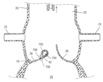
도 4a 내지 도 4g는 봉합사를 사용하여 첨판을 절첩 및/또는 포획하기 위한 예시적인 방법을 도시하고 있다. 도 4a에 도시되어 있는 바와 같이, 전달 카테터(402)는 상행 대동맥(20)으로부터 기존 판막 구조체(예를 들어, 예시된 예에서 자연 대동맥 판막, 또는 예시되어 있지 않은 예에서 이전에 설치된 인공 심장 판막)의 첨판(38) 중 하나를 향해 전진될 수 있다. 예를 들어, 전달 카테터(402)는 그 단부가 첨판(38) 중 하나의 제1 부분에 대면하는 상태로 위치될 수 있다. 제1 부분은 첨판(38)의 자유 단부(42)보다 판막 고리(18)에 더 가까울 수 있고 바람직하게는 관상 동맥(22)의 소공에 대해 원위측에 있다. 몇몇 실시예에서, 첨판(38)의 제1 부분은 관상 동맥(22)의 소공과 원주방향으로 정렬될 수도 있다(예를 들어, 상행 대동맥(20)으로부터 볼 때, 기존 판막 구조체의 중심으로부터 연장하는 동일한 반경방향 벡터를 따라 정렬되거나 실질적으로 정렬됨).4A-4G illustrate exemplary methods for folding and/or capturing leaflets using sutures. As shown in FIG. 4A ,
봉합사(404)가 그에 부착되어 있는 바늘(406)이 전달 카테터(402) 내에 배치될 수 있다. 일단 전달 카테터(402)가 첨판(38)의 제1 부분에 인접하게 배치되면, 바늘(406)은 전달 카테터(402)의 원위 단부 외부로 전진되어 첨판(38)의 제1 부분(408)을 관통할 수 있다. 봉합사(404)를 갖는 바늘(406)은 따라서 도 4b에 도시되어 있는 바와 같이, 제1 부분(408)을 통해 첨판(38)의 원위측으로 이동한다. 봉합사(404)는 이어서 기존 판막 구조체의 첨판(38)의 자유 단부(42) 사이의 중앙 간극(410)을 통해 바늘(406)을 이동시킴으로써 첨판(38)의 근위측으로 다시 견인될 수 있다. 중앙 간극(410)을 통과한 봉합사(404)의 부분(404b)은 이어서 첨판(38)의 제1 부분(408)을 통과하지 않은 봉합사(404)의 부분(404a) 위에 속박될 수 있다.A
매듭(412)이 도 4c에 도시되어 있는 바와 같이, 부분(404b)을 부분(404a)에 속박함으로써 형성된다. 매듭(412) 및 봉합사 부분(404a, 404b)은 제1 부분(408)과 첨판 자유 단부(42) 사이에서 첨판(38)의 부분을 둘러싸는 루프(414)를 형성한다. 매듭(412)은 봉합사(404)를 따라 활주 가능하도록 형성될 수 있다. 몇몇 실시예에서, 매듭(412) 자체의 구성은 예를 들어, 슬립 매듭 또는 다른 활주 매듭을 형성함으로써 매듭이 봉합사(404)를 따라 활주 가능할 수 있게 한다. 대안적으로 또는 부가적으로, 매듭(412)은 초기에 느슨한 상태로 형성되어 매듭(412)이 봉합사(404)를 따라 활주할 수 있게 할 수도 있다. 따라서, 매듭(412)은 루프(414)의 크기를 감소시키기 위해 판막 구조체를 향해 봉합사(404)를 따라 원위측으로 활주될 수 있다. 루프(414)의 크기 감소는 그 내에 포함된 첨판의 부분(즉, 그 자유 단부(42)와 관통된 제1 부분(408) 사이의 첨판(38)의 부분)이 도 4d에 도시되어 있는 바와 같이, 자체로 말리거나 절첩되게 한다.A
몇몇 실시예에서, 판막 구조체를 향해 원위측으로 매듭(412)의 활주는 매듭(412) 및 봉합사(404) 중 적어도 하나를 다른 하나에 대해 이동시킴으로써 실행될 수 있다. 예를 들어, 봉합사(404)는 근위 방향으로 견인될 수 있는데, 이는 루프(414)를 조이고 매듭(412)이 원위측으로 이동하게 할 수 있다. 대안적으로 또는 부가적으로, 매듭(412)은 압박/보조 부재에 의해, 예를 들어 도 4e에 도시되어 있는 바와 같은 활주 부재(416)에 의해 첨판(38)의 관통된 제1 부분(408)을 향해 원위 방향으로 압박될 수 있다. 대안적으로 또는 부가적으로, 매듭(412)은 봉합사(404)가 근위 방향으로 후퇴될 때 압박/보조 부재(예를 들어, 위치설정 부재)에 의해 제자리에 유지될 수 있다. 활주 부재(416)는 봉합사(404)가 그를 통해 연장하는 관통 구멍, 도관 또는 리세스를 가질 수 있고 활주 부재(416)가 그와 접촉하게 될 때 매듭(412)에 맞접하도록 구성된 부분(예를 들어, 원위 단부)을 가질 수 있다. 예를 들어, 활주 부재(416)는 초기에 전달 카테터(402) 내의 봉합사(404) 상에 배치될 수 있고, 활주 부재(416)는 전달 카테터(402)의 원위 단부로부터 상행 대동맥(20) 내로 전달되도록 크기 설정되고 성형될 수 있다. 대안적으로, 압박/보조 부재는 개별 부재(416)보다는 전달 카테터(402)의 원위 단부 부분일 수 있다.In some embodiments, sliding of
루프(414)의 크기 감소량은, 기존 판막 구조체 내의 인공 심장 판막의 후속 장착에 의해 반경방향 외향으로 가압될 때에도 그 내부에 포함된 첨판(38)의 절첩된 부분이 관상 동맥(22)의 소공에 대해 원위측에 위치되도록 선택될 수 있다. 일단 봉합사 루프(414)의 크기의 충분한 감소가 달성되면, 매듭(412)은 도 4f에 도시되어 있는 바와 같이, 제자리에 로킹될 수 있다. 매듭(412)의 로킹은 인공 심장 판막의 설치 중 또는 후에 첨판(38)의 포획된 부분이 펼쳐지지 않는 것을 보장할 수 있다. 예를 들어, 매듭(412)은 예로서 매듭(412)을 조임으로써 및/또는 매듭(412)을 형성하는 봉합사 부분을 접합, 융합 또는 봉입함으로써, 매듭 자체의 조작에 의해 제자리에 로킹될 수 있다. 대안적으로 또는 부가적으로, 매듭(412)은 매듭(412)과 접촉하게 되는 개별 물리적 디바이스(418)에 의해 제자리에 로킹될 수 있다. 몇몇 실시예에서 활주 부재(416)는 매듭(412)에 대해 제자리에 로킹 디바이스(418)를 위치설정하는 데 사용될 수 있다. 로킹 디바이스(418)는 활주 구성(예를 들어, 관통 구멍이 봉합사(404)와 로킹 디바이스(418) 사이의 상대 운동을 허용하는)과 비활주 구성(예를 들어, 예를 들어 봉합사(404)를 관통 구멍의 측벽과 접촉하도록 가압하는 부재에 의해, 관통 구멍이 봉합사(404)와 로킹 디바이스(418) 사이의 상대 운동을 제한하는) 사이에 재구성하도록 구성될 수도 있다. 대안적으로 또는 부가적으로, 로킹 디바이스(418)는 예를 들어 미국 특허 출원 공개 제2018/0177503호 및 제2020/0000458호에 설명된 바와 같이 봉합사 클립 또는 체결구를 포함하며, 이들 모두는 본 명세서에 참조로서 합체되어 있다. 매듭(412)이 제자리에 로킹된 상태에서, 봉합사(404)는 절단되고(예를 들어, 로킹 디바이스(418)에 바로 인접한 장소에서 또는 매듭(412)의 장소에 대해 근위측인 다른 장소에서) 도 4f에 도시되어 있는 바와 같이 전달 카테터(402) 내로 후퇴될 수 있다. 봉합사(404)의 절단은 전달 카테터(402)의 원위 단부로부터 제공되거나 상행 대동맥(20) 내의 개별 카테터를 통해 제공되는 절단 도구에 의해 이루어질 수 있다. 대안적으로, 전달 카테터(402)의 부분(예를 들어, 카테터(402)의 원위 단부)는 봉합사(404)를 절단하기 위한 절단 요소를 포함할 수 있다.The amount of reduction in size of the
따라서, 봉합사 루프(414)는 첨판(38)의 부분을 절첩하고 이를 관상 동맥(22)에 대해 원위측에서 포획하여, 이에 의해 관상 동맥(22)의 소공의 폐색의 위험을 방지하거나 적어도 감소시킨다. 기존 판막 구조체의 하나 이상의 첨판(38)의 부가의 포획/절첩이 예를 들어 관상 동맥(24)의 소공의 폐색의 위험을 방지하거나 적어도 감소시키기 위해 요구되면, 도 4a 내지 도 4f의 기술은 동일한 전달 카테터(402) 또는 상이한 전달 카테터를 사용하여 다음 첨판(38)에 대해 유사한 방식으로 반복될 수 있다. 이러한 반복시에, 바늘(406) 및 봉합사(404)에 의해 관통되는 다음 첨판(38)의 부분은 관상 동맥(24)의 소공과 원주방향으로 정렬될 수 있다(예를 들어, 상행 대동맥(20)으로부터 볼 때, 기존 판막 구조체의 중심으로부터 연장하는 동일한 반경방향 벡터를 따라 정렬되거나 실질적으로 정렬됨). 상기에 상세히 설명되지는 않았지만, 환자의 해부학 구조 내의 바늘(406) 및/또는 봉합사(404)의 조작, 압박/보조 부재(예를 들어, 활주 부재(416)) 또는 로킹 디바이스(418)의 이동, 및/또는 매듭(412)의 조작(예를 들어, 매듭을 이동시키거나 로킹하기 위한)은 이들에 한정되는 것은 아니지만, 매듭 푸셔, 봉합사 절단기, 매니퓰레이터 등과 같은 복강경 및/또는 경도관 심장 수술에 채용되는 임의의 도구를 사용하여 수행될 수도 있다.Thus,
첨판 포획이 더 이상 요구되지 않을 때, 크림핑 상태의 새로운 인공 심장 판막이 이후에 포획된 첨판(38)을 갖는 기존 판막 구조체로 전진될 수 있다. 예를 들어, 도 4g에 도시되어 있는 바와 같이, 새로운 인공 판막(10)(도 2a의 판막(10) 또는 상이한 인공 판막일 수 있음)은 전달 장치(450)의 벌룬 상에 반경방향으로 크림핑될 수 있다. 전달 카테터(450)는 첨판(38) 사이에 인공 판막(10)을 위치설정하기 위해 대동맥을 통해 자연 대동맥 판막을 향해 전진될 수 있다. 새로운 인공 판막(10)은 이어서 전달 카테터의 벌룬을 팽창시킴으로써 팽창되어, 포획된 첨판(38)이 새로운 판막 프레임의 외부면 상에 배치되게 된다. 그러나, 로킹된 봉합사 루프(414)는 관상 동맥(22, 24)에 대해 원위측인 장소에 포획 첨판(38)을 유지하여, 이에 의해 일단 심장 판막 이식이 완료되면 새로운 인공 판막의 유출 단부로부터 관상 동맥(22, 24)으로 혈액이 유동할 수 있게 한다. 전달 장치 및 전달 장치를 사용하여 인공 판막을 이식하기 위한 방법의 추가 상세는 미국 특허 제7,780,723호, 제9,061,119호 및 제9,339,384호, 및 미국 특허 출원 공개 제2017/0065415호에 개시되어 있으며, 이들 모두는 본 명세서에 참조로서 합체되어 있다.When leaflet capture is no longer required, the new prosthetic heart valve in the crimped state can then be advanced onto the existing valve structure with the captured
다른 실시예에서, 인공 판막(10)은 모두는 본 명세서에 참조로서 합체되어 있는 미국 특허 출원 공개 제2014/0343670호 및 미국 특허 제8,652,202호에 개시된 바와 같은, 전달 장치의 캡슐 또는 전달 외장 내에 반경방향 압축 상태로 유지되는 자기-팽창 가능 인공 판막일 수 있다. 일단 인공 판막이 첨판(38) 사이에 위치되면, 인공 판막은 전달 외장으로부터 전개될 수 있는데, 이는 인공 판막이 첨판에 대해 반경방향 팽창 상태로 자기-팽창할 수 있게 한다.In another embodiment,
다른 실시예에서, 인공 판막(10)은 본 명세서에 참조로서 합체되어 있는 미국 특허 출원 공개 제2018/0153689호, 미국 출원 제62/990,299호, 국제 출원 번호 PCT/US2020/063104에 개시된 바와 같은, 전달 장치의 하나 이상의 기계적 액추에이터에 해제 가능하게 연결되는 기계적 팽창 가능 인공 판막일 수 있다. 인공 판막은 전달 장치(선택적으로 전달 외장 내에 있음)에 의해 반경방향 압축 상태로 유지되고 첨판(38) 사이에 위치된다. 일단 위치되면, 인공 판막은 전달 외장으로부터 전개될 수 있고 전달 장치의 하나 이상의 기계적 액추에이터를 작동시킴으로써 첨판에 대해 반경방향 팽창 상태로 반경방향으로 팽창될 수 있다.In another embodiment, the
몇몇 실시예에서, 제1 부재(예를 들어, 봉합사, 와이어, 스레드 또는 다른 구조체)는 첨판의 제1 부분에 속박되고, 제2 부재(예를 들어, 봉합사, 와이어, 스레드 또는 다른 구조체)는 첨판의 제2 부분에 속박된다. 첨판의 제2 부분은 첨판의 자유 단부 부근에 있을 수 있고, 반면 첨판의 제1 부분은 첨판의 베이스 또는 앵커부(예를 들어, 첨판의 최원위 부분) 부근에 있을 수 있다. 제1 및 제2 부재는 하나 이상의 앵커 또는 주름부에 의해 각각의 제1 및 제2 부분에 속박될 수 있다. 제1 및 제2 부재를 서로를 향해 견인함으로써, 첨판의 제2 부분은 첨판의 제1 부분을 향해 견인되고, 이에 의해 첨판의 부분이 제1 및 제2 부분 사이에서 절첩된다. 일단 첨판의 충분한 절첩이 달성되면(예를 들어, 일단 인공 심장 판막이 기존 판막 구조체 내에 설치되면 관상 동맥의 소공을 폐색하지 않을 것인 크기 및/또는 장소의 감소), 서로에 관한 제1 및 제2 부재의 장소는 로킹되어 첨판의 절첩 구성을 유지할 수 있고, 새로운 인공 심장 판막이 이후에 설치될 수 있다.In some embodiments, a first member (eg, suture, wire, thread, or other structure) is constrained to a first portion of the leaflet, and a second member (eg, suture, wire, thread, or other structure) is constrained to the first portion of the leaflet. It is constrained to the second part of the leaflet. A second portion of the leaflet may be near the free end of the leaflet, while a first portion of the leaflet may be near the base or anchor portion of the leaflet (eg, the most distal portion of the leaflet). The first and second members may be constrained to the respective first and second portions by one or more anchors or pleats. By pulling the first and second members toward each other, the second portion of the leaflet is drawn toward the first portion of the leaflet, thereby folding the portion of the leaflet between the first and second portions. Once sufficient folding of the leaflets is achieved (eg, reduction in size and/or location that will not occlude the foramen of the coronary artery once the prosthetic heart valve is installed within the existing valve structure), first and second relative to each other. The two pieces may be locked in place to maintain the folded configuration of the leaflets, and a new prosthetic heart valve may then be installed.
도 5a 내지 도 5h는 속박된 봉합사를 사용하여 첨판을 절첩 및/또는 포획하기 위한 예시적인 방법을 도시하고 있다. 도 5a에 도시되어 있는 바와 같이, 전달 카테터(502)는 상행 대동맥(20)으로부터 기존 판막 구조체(예를 들어, 예시된 예에서 자연 대동맥 판막, 또는 예시되어 있지 않은 예에서 이전에 설치된 인공 심장 판막)의 첨판(38) 중 하나를 향해 전진될 수 있다. 예를 들어, 전달 카테터(502)는 그 단부가 첨판(38) 중 하나의 제1 부분에 대면하는 상태로 위치될 수 있다. 제1 부분은 첨판(38)의 자유 단부(42)보다 판막 고리(18)에 더 가까울 수 있고 바람직하게는 관상 동맥(22)의 소공에 대해 원위측에 있다. 몇몇 실시예에서, 첨판(38)의 제1 부분은 관상 동맥(22)의 소공과 원주방향으로 정렬될 수도 있다(예를 들어, 상행 대동맥(20)으로부터 볼 때, 기존 판막 구조체의 중심으로부터 연장하는 동일한 반경방향 벡터를 따라 정렬되거나 실질적으로 정렬됨).5A-5H illustrate exemplary methods for folding and/or capturing leaflets using constrained sutures. As shown in FIG. 5A ,
제1 봉합사(504)가 그에 부착되어 있는 바늘(506)이 전달 카테터(502) 내에 배치될 수 있다. 일단 전달 카테터(502)가 첨판(38)의 제1 부분에 인접하게 배치되면, 바늘(506)은 전달 카테터(502)의 원위 단부 외부로 전진되어 첨판(38)의 제1 부분(508)을 관통할 수 있다. 제1 봉합사(504)를 갖는 바늘(506)은 따라서 도 5b에 도시되어 있는 바와 같이, 제1 부분(508)을 통해 첨판(38)의 원위측으로 이동한다. 제1 부분(508)에서, 제1 봉합사(504)를 첨판(38)에 속박하기 위해 적어도 하나의 앵커가 형성될 수 있다. 예를 들어, 원위측 앵커(510)가 제1 부분(508)에 형성될 수 있다. 대안적으로 또는 부가적으로, 근위측 앵커(512)가 제1 부분(508)에 형성될 수 있다. 도 5c에 도시되어 있는 바와 같이, 제1 봉합사(504)는 원위측 앵커(510)와 근위측 앵커(512) 사이에서 연장될 수 있다.A
예를 들어, 각각의 앵커(510, 512)는 제1 봉합사(504)의 매듭 부분, 천 또는 직물의 단편, 첨판으로부터 형성된 주름부, 및/또는 로킹 부재를 포함할 수 있다. 원위측 앵커를 형성하기 위해, 앵커링 구성요소(예를 들어, 직물, 클립 등)는 봉합사를 갖는 첨판의 관통된 부분을 통과할 수 있고 원위측에서 팽창될 수 있다. 근위측 앵커를 형성하기 위해, 앵커링 구성요소는 예를 들어 전달 카테터로부터 봉합사를 아래로 활주시킴으로써 첨판의 근위측 표면으로 운반될 수 있다. 예를 들어, 각각의 앵커(510, 512)는 본 명세서에 참조로서 합체되어 있는 미국 특허 출원 공개 제2018/0177503호 및 제2020/0000458호에 개시된 봉합사 체결구 또는 봉합사 클립 중 하나 이상을 포함할 수 있다. 첨판에 대한 봉합사 부착의 추가 상세는 또한 본 명세서에 참조로서 합체되어 있는 미국 특허 출원 공개 제2015/0230919호에서 발견될 수 있다.For example, each
도 5d에 도시되어 있는 바와 같이, 다른 전달 카테터(520)가 상행 대동맥(20)으로부터 전진되고 그 원위 단부가 동일한 첨판(38)의 제2 부분에 대면하는 상태로 위치될 수 있다. 제2 부분은 제1 부분(508)보다 첨판(38)의 자유 단부(42)에 더 가까울 수 있다. 몇몇 실시예에서, 첨판(38)의 제2 부분은 또한 관상 동맥(22)의 소공과 원주방향으로 정렬될 수도 있다(예를 들어, 상행 대동맥(20)으로부터 볼 때, 기존 판막 구조체의 중심으로부터 연장하는 동일한 반경방향 벡터를 따라 정렬되거나 실질적으로 정렬됨). 제2 봉합사(514)가 그에 부착되어 있는 다른 바늘(516)이 전달 카테터(520) 내에 배치될 수 있다. 일단 전달 카테터(520)가 첨판(38)의 제2 부분에 인접하게 배치되면, 바늘(516)은 전달 카테터(502)의 원위 단부 외부로 전진되어 첨판(38)의 제2 부분(518)을 관통할 수 있다. 제2 봉합사(514)를 갖는 바늘(516)은 따라서 도 5e에 도시되어 있는 바와 같이, 제2 부분(518)을 통해 첨판(38)의 원위측으로 이동한다.As shown in FIG. 5D , another
제2 부분(518)에서, 제2 봉합사(514)를 첨판(38)에 속박하기 위해 적어도 하나의 앵커가 형성될 수 있다. 예를 들어, 원위측 앵커(522)가 제2 부분(518)에 형성될 수 있다. 대안적으로 또는 부가적으로, 근위측 앵커(524)가 제2 부분(518)에 형성될 수 있다. 도 5f에 도시되어 있는 바와 같이, 제2 봉합사(514)는 원위측 앵커(522)와 근위측 앵커(524) 사이에서 연장될 수 있다. 앵커(510, 512)와 유사하게, 각각의 앵커(522, 524)는 제1 봉합사(504)의 매듭 부분, 첨판으로부터 형성된 주름부, 및/또는 로킹 부재일 수 있고 그리고/또는 봉합사 체결구 또는 봉합사 클립 중 하나 이상을 사용할 수 있다. 전달 카테터(520)의 위치설정 및 제2 부분(518)에서의 앵커(522, 524)의 형성은 전달 카테터(502)의 위치설정 및 제1 부분(508)에서의 앵커(510, 512)의 형성 후에 설명되었지만, 이러한 설명은 단지 편의를 위한 것이다. 실제로, 도 5a 내지 도 5f와 관련하여 전술된 단계는 동시에 또는 설명된 것과는 상이한 순서로 발생할 수도 있다.At
일단 봉합사(504, 514)가 그 각각의 앵커에 의해 첨판(38)의 제1 부분(508) 및 제2 부분(518)에 속박되면, 도 5g에 도시되어 있는 바와 같이, 전달 카테터(502, 520)는 후퇴될 수 있고 커플링 부재(530)가 제공될 수 있는데, 이는 예를 들어 상행 대동맥을 통해 봉합사(504, 514) 위에 삽입된 다른 카테터를 통해 전달될 수 있다. 커플링 부재(530)는 봉합사(504, 514)가 그를 통해 연장하는 하나 이상의 관통 구멍, 도관 또는 리세스를 가질 수 있다. 예를 들어, 커플링 부재(530)는 한 쌍의 관통 구멍(532, 534)을 갖는 활주 부재일 수 있다. 제1 봉합사(504)는 제1 관통 구멍(532)을 통해 연장할 수 있고, 반면 제2 봉합사(514)는 제2 관통 구멍(534)을 통해 연장할 수 있다. 관통 구멍(532, 534) 사이의 측방향 거리는 첨판(38)의 윤곽을 따른 제1 부분(508)과 제2 부분(518) 사이의 거리보다 더 작을 수 있다. 따라서, 커플링 부재(530)가 상행 대동맥(20)으로부터 첨판(38)을 향해 원위측으로 전진될 때, 관통 구멍(532, 534) 사이의 간격은 첨판(38)의 제1 및 제2 부분(508, 518)을 서로를 향해 견인하여, 이에 의해 첨판(38)이 절첩되게 한다. 특히, 앵커링 부분(526)(예를 들어, 판막 고리(18)에 가장 근접함)과 앵커링 부분(528)(예를 들어, 자유 단부(42)에 가장 근접함) 사이의 첨판의 부분(538)은, 도 5h에 도시되어 있는 바와 같이, 앵커(510/512)와 앵커(522/524) 사이에 주름진 구성을 갖도록, 또는 적어도 관상 동맥(22)으로부터 이격하여 원위측으로 연장되도록 자체로 절첩될 수 있다. 대안적으로, 커플링 부재는 단일 관통 구멍을 갖는 활주 부재일 수 있다. 제1 및 제2 봉합사(504, 514)의 모두는 동일한 관통 구멍을 통해 연장될 수 있다. 관통 구멍의 원위 단부의 측방향 치수(예를 들어, 직경)는 첨판(38)의 윤곽을 따른 제1 부분(508)과 제2 부분(518) 사이의 거리보다 더 작을 수 있다. 따라서, 커플링 부재가 첨판(38)을 향해 전진됨에 따라, 관통 구멍의 측벽은 첨판(38)의 제1 및 제2 부분(508, 518)을 서로를 향해 견인하여, 이에 의해 첨판(38)이 절첩되게 한다.Once
몇몇 실시예에서, 첨판(38)의 제1 부분(508)에 제1 봉합사(504)를 속박하는 데 사용되는 전달 카테터(502)는 제2 부분(518)에 제2 봉합사(514)를 속박하는 데 사용되는 것과 동일할 수 있다. 예를 들어, 제1 부분(508)에서 앵커(510, 512)를 형성한 후, 봉합사(504)는 전달 카테터(502)의 원위 단부와 앵커(512) 사이의 장소에서 절단될 수 있고, 봉합사(504)의 절단된 부분은 커플링 부재와 후속 사용을 위해 유지된다. 따라서, 전달 카테터(502)는 예를 들어 도 5f의 전달 카테터(520)와 같이, 제2 부분(518)에 대해 자유롭게 재위치설정된다. 대안적으로, 제1 부분(508)에서 앵커(510, 512)를 형성한 후, 제1 봉합사(504)는 제2 부분(518)에 대한 재위치설정 동안 전달 카테터(502)의 단부로부터 연장하는 상태로 유지된다. 제2 바늘(516) 및 제2 봉합사(514)는 전달 카테터(502)로부터 연장될 수 있고, 반면 제1 봉합사(504)는 제1 부분(508)과 카테터(502) 사이에서 계속 연장된다. 이러한 구성에서, 전달 카테터(502)는 앵커(522, 524)를 형성한 후에 제1 부분(508)과 제2 부분(518)을 함께 견인하기 위한 "단일 관통 구멍" 커플링 부재로서 사용될 수도 있다.In some embodiments, the
일단 커플링 부재(530)가 근위측 앵커(512, 524)와 접촉하면 그리고/또는 첨판이 다른 방식으로 충분한 절첩을 달성할 때(기존 판막 구조체 내의 인공 심장 판막의 후속 장착에 의해 반경방향 외향으로 가압될 때에도, 절첩된 첨판(38)이 관상 동맥(22)의 소공에 대해 원위측에 위치됨), 커플링 부재(530)는 도 5h에 도시되어 있는 바와 같이, 앵커링 부분(526, 528)에 대해 제자리에 로킹될 수 있다. 커플링 부재(530)의 로킹은 인공 심장 판막의 설치 중 또는 후에 첨판(38)의 절첩된 부분이 펼쳐지지 않는 것을 보장할 수 있다. 예를 들어, 커플링 부재(530)는 커플링 부재(530)의 근위측과 접촉하게 되는 개별 물리적 디바이스(536)에 의해 제자리에 로킹될 수 있다. 대안적으로 또는 부가적으로, 커플링 부재(530)는 활주 구성(예를 들어, 관통 구멍(532, 534)이 봉합사(504, 514)와 커플링 부재(530) 사이의 상대 운동을 허용하는)과 비활주 구성(예를 들어, 예를 들어 각각의 관통 구멍의 측벽과 접촉하게 봉합사(504, 514)를 가압하는 부재에 의해, 각각의 관통 구멍(532, 534)이 봉합사(504, 514)와 커플링 부재(530) 사이의 상대 운동을 제한하는) 사이에서 재구성되도록 구성될 수도 있다. 대안적으로 또는 부가적으로, 커플링 부재(530)는 봉합사 자체의 조작에 의해 제자리에 로킹될 수 있다. 예를 들어, 커플링 부재(530)의 근위측 외부로 연장하는 봉합사(504, 514)의 자유 단부는 커플링 부재를 제자리에 로킹하기 위해 함께 결합될 수 있다(예를 들어, 속박, 접합, 융합, 또는 봉입에 의해).Once the
커플링 부재(530)가 제자리에 로킹된 상태에서, 각각의 봉합사(504, 514)는 절단되고(예를 들어, 로킹 디바이스(536)에 바로 인접한 장소에서 또는 커플링 부재의 장소에 대해 근위측인 다른 장소에서) 도 5h에 도시되어 있는 바와 같이 근위측으로 후퇴될 수 있다. 각각의 봉합사(504, 514)의 절단은 어느 하나의 전달 카테터(502, 520)의 원위 단부로부터 제공되거나 상행 대동맥(20) 내의 개별 카테터를 통해 제공되는 절단 도구에 의해 이루어질 수 있다. 대안적으로, 전달 카테터(502, 520) 중 하나 또는 모두의 부분(예를 들어, 카테터(502, 520)의 원위 단부)는 각각의 봉합사(504, 514)를 절단하기 위한 절단 요소를 포함할 수 있다.With the
따라서, 서로를 향해 견인된 앵커링 부분(526, 528)은 첨판 부분(538)을 포획하여 절첩하고 첨판 자유 단부(42)를 관상 동맥(22)에 대해 원위측에 위치시켜, 이에 의해 관상 동맥(22)의 소공의 폐색의 위험을 방지하거나 적어도 감소시킨다. 기존 판막 구조체의 하나 이상의 첨판(38)의 부가의 포획/절첩이 예를 들어 관상 동맥(24)의 소공의 폐색의 위험을 방지하거나 적어도 감소시키기 위해 요구되면, 도 5a 내지 도 5h의 기술은 동일한 전달 카테터(502, 520) 또는 상이한 전달 카테터를 사용하여 다음 첨판(38)에 대해 유사한 방식으로 반복될 수 있다. 이러한 반복시에, 바늘(506, 516)에 의해 각각 관통되는 다음 첨판(38)의 부분은 관상 동맥(24)의 소공과 원주방향으로 정렬될 수 있다(예를 들어, 상행 대동맥(20)으로부터 볼 때, 기존 판막 구조체의 중심으로부터 연장하는 동일한 반경방향 벡터를 따라 정렬되거나 실질적으로 정렬됨). 상기에 상세히 설명되지는 않았지만, 환자의 해부학 구조 내의 바늘(506, 516) 및/또는 봉합사(504, 514)의 조작, 앵커(510, 512, 522, 524)의 형성 또는 설치, 및/또는 커플링 부재(530) 또는 로킹 디바이스(536)의 이동은 이들에 한정되는 것은 아니지만, 봉합사 절단기, 매니퓰레이터 등과 같은 복강경 및/또는 경도관 심장 수술에 채용되는 임의의 도구를 사용하여 수행될 수도 있다.Thus, the anchoring
첨판 포획/절첩이 더 이상 요구되지 않을 때, 크림핑 상태의 새로운 인공 심장 판막이 이후에 포획된 첨판(38)을 갖는 기존 판막 구조체로 전진될 수 있다(도 4g에 도시되어 있는 바와 같이). 새로운 판막은 판막 구조체 내에 배치되고 팽창되어, 포획된 첨판(38)이 새로운 판막 프레임의 외부면 상에 배치되게 된다. 그러나, 근접된 앵커링 부분(526, 528)은 관상 동맥(22, 24)에 대해 원위측인 위치에 첨판(38)을 유지하여, 이에 의해 일단 심장 판막 이식이 완료되면 새로운 인공 판막의 유출 단부로부터 관상 동맥(22, 24)으로 혈액이 유동할 수 있게 한다.When leaflet capture/folding is no longer required, the new prosthetic heart valve in the crimped state can then be advanced onto the existing valve structure with the captured leaflet 38 (as shown in FIG. 4G). The new valve is placed within the valve structure and inflated, causing the captured
몇몇 실시예에서, 로킹 디바이스는 절첩 구성에서 그리고 대응 관상 소공을 폐색하는 것을 회피하는 위치에서 첨판을 포획하는 데 사용될 수 있다. 로킹 디바이스는 첨판의 자유 단부 위로 개방 구성으로 전진될 수 있다. 로킹 디바이스 또는 그 액추에이터의 부분은 로킹 디바이스가 첨판 위로 더 전진함에 따라 로킹 디바이스의 대향 부재 사이에 첨판의 부분을 개더링할 수 있다. 일단 첨판의 충분한 부분이 개더링되면(예를 들어, 일단 인공 심장 판막이 기존 판막 구조체 내에 설치되면 그렇지 않으면 관상 동맥의 소공을 폐색하지 않을 것인 크기 및/또는 장소의 감소), 로킹 디바이스는 로킹 디바이스 부재가 서로 접근하여 그 사이에 첨판의 개더링된 부분에 접촉하고 유지하는 폐쇄 구성으로 전이할 수 있고, 새로운 인공 심장 판막이 이후에 설치될 수 있다.In some embodiments, the locking device may be used to capture the leaflet in a collapsed configuration and in a position that avoids occluding the corresponding coronal foramen. The locking device can be advanced in an open configuration over the free end of the leaflet. The locking device or part of its actuator may gather part of the leaflet between opposing members of the locking device as the locking device advances further over the leaflet. Once a sufficient portion of the leaflet is gathered (e.g., reduced in size and/or location that would not otherwise occlude a coronary stomata once the prosthetic heart valve is installed within the existing valve structure), the locking device is The members can approach each other and transition to a closed configuration where they contact and hold the gathered portion of the leaflet between them, and a new prosthetic heart valve can then be installed.
도 6a 및 도 6b는 예시적인 로킹 디바이스를 도시하고 있고, 도 6c 내지 도 6e는 예시적인 로킹 디바이스를 사용하여 첨판을 절첩 및/또는 포획하기 위한 예시적인 방법을 도시하고 있다. 특히, 도 6a는 개방 구성에서의 로킹 디바이스(600)를 도시하고 있고, 도 6b는 폐쇄 구성에서의 로킹 디바이스(600)를 도시하고 있다. 로킹 디바이스(600)는 제1 부재(602) 및 제2 부재(614)를 가질 수 있다. 개방 구성에서, 제1 부재(602)는 제2 부재(614)로부터 이격되어 그 사이에 간극(620)을 형성한다. 폐쇄 구성에서, 제1 부재(602)와 제2 부재(614)는 간극(620)을 제거하거나 적어도 그 크기를 감소시키기 위해 서로 접근한다. 제1 부재(602)는 예를 들어, 하나 이상의 리세스(604)를 갖는 암형 부재로서 구성될 수 있다. 제2 부재(614)는 수형 부재, 예를 들어 하나 이상의 돌출부 또는 갈래(616)로서 구성될 수 있다. 각각의 돌출부(616)는 리세스(604) 중 하나에 대응하고, 돌출부(616)는 개방 구성에서 대응 리세스(604)로부터 이격되고 정렬되며, 돌출부(616)는 폐쇄 구성에서 대응 리세스(604)의 부분 내에 삽입되어 접촉한다. 각각의 돌출부(616)는 로킹 디바이스(600)가 개방 구성으로부터 폐쇄 구성으로 전이함에 따라 간극(620) 내의 첨판을 관통하도록 구성된 날카로운 팁을 가질 수 있다.6A and 6B illustrate an exemplary locking device, and FIGS. 6C-6E illustrate an exemplary method for folding and/or capturing leaflets using the exemplary locking device. In particular, FIG. 6A shows the
돌출부(616) 및 리세스(604)는 예를 들어, 일단 돌출부(616)가 폐쇄 구성에서 리세스(604)에 삽입되면 리세스(604)로부터 돌출부(616)의 제거를 방지하기 위해, 하나 이상의 스냅 끼워맞춤 특징부로 구성될 수 있다. 예를 들어, 돌출부(616)는 미늘이 있는 부분(618)을 포함할 수도 있고, 리세스(604)는 그 내부에 리지(606)를 포함할 수도 있다. 로킹 디바이스(600)가 폐쇄 구성으로 전이함에 따라, 돌출부(616)는 미늘이 있는 부분(618)의 에지가 리지(606)에 맞접하여 리세스(604)로부터 돌출부(616)의 인출에 저항하도록 리세스(604) 내에 삽입된다. 몇몇 실시예에서, 돌출부(616)는 예를 들어 제1 및 제2 부재(602, 614) 사이의 첨판의 개더링 부분에 대한 두께의 변동을 수용하기 위해 다수의 미늘이 있는 부분을 포함한다. 리세스(604)와 돌출부(616) 사이의 스냅 끼워맞춤 로킹 특징부에 추가하여, 또는 그 대신에, 로킹 디바이스(600)는 이들에 한정되는 것은 아니지만, 예를 들어 간극(620)에 인접한 부재(602, 614)의 외부 부분 상에 배치된 선형 래칫과 같은 하나 이상의 외부 로킹 특징부를 포함할 수 있다. 이러한 대안적인 구성에서, 선형 래칫은 이하에 더 설명되는 바와 같이, 개더링 부재로서 사용될 수 있다.
단지 하나의 돌출부(616) 및 하나의 리세스(604)만이 도 6a 및 도 6b에 도시되어 있지만, 개시된 주제의 실시예는 이에 한정되지 않는다. 오히려, 제2 부재(614)는 다수의 개별 돌출부(616)를 가질 수 있고, 제1 부재(602)는 다수의 대응 리세스(604)를 가질 수 있다. 더욱이, 각각의 부재(602, 614)는 돌출부(616) 또는 리세스(604) 중 단지 하나만을 갖는 것으로 도시되어 있지만, 부재(602, 614)는 몇몇 실시예에서 양자 모두를 포함할 수도 있다. 예를 들어, 제2 부재(614)는 돌출부(616)에 추가하여 하나 이상의 리세스를 가질 수 있고, 제1 부재(602)는 리세스(604)에 추가하여 하나 이상의 돌출부를 가질 수 있다. 다수의 돌출부 및 리젝션을 갖는 실시예에서, 돌출부-리세스 쌍 중 하나, 일부 또는 모두는 스냅 끼워맞춤 특징부를 포함할 수 있다.Although only one
개방 구성으로부터 폐쇄 구성으로의 로킹 디바이스(600)의 전이는 액추에이터에 의해 실행될 수 있다. 예를 들어, 액추에이터는 도 6a에 도시되어 있는 것과 같은 가위형 액추에이터(612)일 수 있다. 액추에이터(612)는 제1 부재(602)의 커플링부(608)에 부착된 제1 아암(610) 및 제2 부재(614)의 커플링부(622)에 부착된 제2 아암(624)을 가질 수 있다. 제1 아암(610) 및 제2 아암(624)은 힌지(626)에서 함께 커플링될 수 있는데, 이는 아암(610, 624)이 서로에 대해 회전할 수 있게 한다. 단부를 함께 압박하는 압축력의 단부(628, 630)에서의 인가는 아암(610, 624)이 힌지(626)를 중심으로 피봇하게 하여 이에 의해 제1 부재(602)와 제2 부재(614)를 서로를 향해 압박한다. 액추에이터 아암(610, 624)은 각각의 커플링부(608, 622)에 해제 가능하게 부착될 수 있어, 액추에이터(612)가 예를 들어, 도 6b에 도시되어 있는 바와 같이, 폐쇄 구성으로 배치된 후에 로킹 디바이스(600)로부터 제거될 수 있게 된다. 다른 스타일의 액추에이터가 하나 이상의 고려된 실시예에 따라 또한 가능하다. 실제로, 리세스(604)와 돌출부(616) 사이의 정렬을 유지하면서 환자의 상행 대동맥 내에서 동작하고 제1 및 제2 부재(602, 614)를 서로를 향해 제어 가능하게 이동하는 것이 가능한 임의의 액추에이터가 사용될 수 있다.The transition of the
몇몇 실시예에서, 액추에이터(612)는 로킹 디바이스(600)가 판막 고리를 향해 첨판의 자유 단부로부터 이동함에 따라 첨판의 부분을 간극(620) 내로 개더링시키도록 설계된 간극(620)에 인접한 영역(632)을 형성한다. 예를 들어, 영역(632)은 간극(620)에 대면하는 힌지(626)에서 아암(610, 624)의 부분에 의해 형성될 수 있다. 대안적으로 또는 부가적으로, 개별 구조체(예를 들어, 개더링 부재)가 액추에이터(612)와 간극(620) 사이에 배치될 수 있고 첨판을 개더링하는 데 사용될 수 있다. 예를 들어, 개더링 부재는 영역(632)에서 커플링부(608, 622) 사이에서 연장하는 봉합사, 와이어 또는 스레드를 포함할 수도 있다. 다른 예에서, 개더링 부재는 액추에이터 아암(610, 624)이 서로에 대해 비제한되어 이동할 수 있게 하는 슬롯을 갖는, 영역(632)에서 액추에이터 아암(610, 624) 사이에서 연장하는 바아일 수도 있다.In some embodiments, the
도 6c에 도시되어 있는 바와 같이, 액추에이터(612)를 갖는 로킹 디바이스(600)는 상행 대동맥(20)으로부터 개방 구성으로 전진되어 기존 판막 구조체(예를 들어, 예시된 예에서 자연 대동맥 판막, 또는 예시되어 있지 않은 예에서 이전에 설치된 인공 심장 판막))의 첨판(38) 중 하나에 대해 위치될 수 있다. 예를 들어, 첨판(38)의 자유 단부(42)는 제1 부재(602)와 제2 부재(614) 사이의 간극(620) 내에 배열될 수 있다. 액추에이터(612)를 갖는 로킹 디바이스(600)는 이어서 도 6d에 도시되어 있는 바와 같이, 첨판(38)을 따라 더 전진될 수 있다. 예를 들어, 로킹 디바이스(600)가 판막 고리(18)를 향해 이동함에 따라, 액추에이터(612)의 힌지(626)에 인접한 영역(632)은 첨판(38)의 자유 단부(42)에 맞접하고 이를 자체로 절첩하게 하여, 첨판(38)의 절첩된 부분(634)이 간극(620) 내에 개더링되게 한다. 대안적으로 또는 부가적으로, 간극(620)과 영역(632) 사이의 개더링 부재는, 로킹 디바이스(600)가 전진함에 따라 첨판(38)이 자체로 절첩하게 하기 위해 첨판(38)의 자유 단부(42)와 접촉할 수 있다.As shown in FIG. 6C , a
로킹 디바이스의 전진량은, 기존 판막 구조체 내에 인공 심장 판막의 후속 장착에 의해 반경방향 외향으로 가압될 때에도, 첨판(38)의 근위 절첩된 에지(636)가 관상 동맥(22)의 소공에 대해 원위측에 위치되도록 선택될 수 있다. 일단 로킹 디바이스(600)가 첨판 위로 충분히 전진되면, 액추에이터(612)가 작동되어 도 6e에 도시되어 있는 바와 같이 로킹 디바이스(600)를 폐쇄 구성으로 전이할 수 있다. 따라서, 제2 부재(614)의 돌출부는 제1 부재(602)를 향해 이동하여, 이에 의해 제1 부재(602)의 대응 리세스 내로 삽입되기 전에, 간극(620) 내에서 첨판의 절첩된 부분을 관통한다. 폐쇄 구성으로의 전이는 예를 들어, 전술된 스냅 끼워맞춤 특징부 중 하나 이상을 통해 제1 및 제2 부재를 함께 추가로 로킹할 수 있다. 로킹 디바이스의 로킹은 인공 심장 판막의 설치 중 또는 후에 첨판(38)의 포획된 부분(634)이 펼쳐지지 않는 것을 보장할 수 있다. 액추에이터(612)는 따라서 로킹 디바이스(600)로부터 해제될 수 있고 이후에 다른 첨판 상에 로킹 디바이스를 설치하거나 환자로부터 다른 방식으로 회수하는 데 사용될 수 있다.The amount of advancement of the locking device ensures that the proximal folded
따라서, 로킹 디바이스(600)의 설치는 첨판(38)의 부분을 절첩하고 이를 관상 동맥(22)에 대해 원위측에서 포획하여, 이에 의해 관상 동맥(22)의 소공의 폐색의 위험을 방지하거나 적어도 감소시킨다. 기존 판막 구조체의 하나 이상의 첨판(38)의 부가의 포획/절첩이 예를 들어 관상 동맥(24)의 소공의 폐색의 위험을 방지하거나 적어도 감소시키기 위해 요구되면, 도 6c 내지 도 6f의 기술은 다른 로킹 디바이스 및 동일한 액추에이터(612) 또는 상이한 액추에이터를 사용하여 다음 첨판(38)에 대해 유사한 방식으로 반복될 수 있다. 상기에 상세히 설명되지는 않았지만, 환자의 해부학 구조 내의 로킹 디바이스(600) 및/또는 액추에이터(612)의 조작, 액추에이터(612)의 작동, 및/또는 액추에이터(612)의 디커플링은 복강경 및/또는 경도관 심장 수술에 채용되는 임의의 도구를 사용하여 수행될 수도 있다.Thus, the installation of the
첨판 포획이 더 이상 요구되지 않을 때, 크림핑 상태의 새로운 인공 심장 판막이 이후에 로킹 디바이스(600)에 의해 포획된 첨판(38)을 갖는 기존 판막 구조체로 전진될 수 있다(도 4g에 도시되어 있는 바와 같이). 새로운 판막은 판막 구조체 내에 배치되고 팽창되어, 포획된 첨판(38)이 새로운 판막 프레임의 외부면 상에 배치되게 된다. 그러나, 로킹 디바이스(600)는 관상 동맥(22, 24)에 대해 원위측인 장소에 포획된 첨판(38)을 유지하여, 이에 의해 일단 심장 판막 이식이 완료되면 새로운 인공 판막의 유출 단부로부터 관상 동맥(22, 24)으로 혈액이 유동할 수 있게 한다.When leaflet capture is no longer required, the new prosthetic heart valve in the crimped state can then be advanced onto the existing valve structure with
몇몇 실시예에서, 클립 부재는 절첩 구성에서 그리고 대응 관상 소공을 폐색하는 것을 회피하는 위치에서 첨판을 포획하는 데 사용될 수 있다. 클립 부재는 편향 상태와 자유 상태를 가질 수 있다. 편향 상태에서, 클립 부재의 단부는 클립 부재의 대향 단부에 유지될 수도 있다(예를 들어, 실질적으로 선형 구성을 가짐). 자유 상태에서, 클립 부재의 단부는 클립 부재가 포획 영역을 적어도 부분적으로 경계 한정하도록 서로 접근한다. 클립 부재는 편향 상태에서 첨판의 자유 단부 위로 전진될 수 있다. 클립 부재의 일 단부는 첨판의 원위측에 배치될 수 있다. 클립 부재는 이어서 편향 상태로부터 해제되어, 이에 의해 자유 상태로 전이되고 포획 영역 내에 첨판의 부분을 포획할 수 있다. 새로운 인공 심장 판막이 이후에 설치될 수 있다.In some embodiments, the clip member may be used to capture the leaflet in a collapsed configuration and in a position that avoids occluding the corresponding coronal foramen. The clip member may have a biased state and a free state. In the deflected state, the end of the clip member may be retained at the opposite end of the clip member (eg, having a substantially linear configuration). In the free state, the ends of the clip members approach each other such that the clip members at least partially bound the capture area. The clip member can be advanced over the free end of the leaflet in a deflected condition. One end of the clip member may be disposed distal to the leaflet. The clip member can then be released from the biased state, thereby transitioning to a free state and capturing a portion of the leaflet within the trapping area. A new prosthetic heart valve may then be installed.
도 7a는 자유 상태에서의 예시적인 클립 부재를 도시하고 있고, 도 7b 내지 도 7d는 예시적인 클립 부재를 사용하여 첨판을 절첩 및/또는 포획하기 위한 예시적인 방법을 도시하고 있다. 클립 부재(700)는 중간 부분(702)에 의해 함께 연결된 단부(706, 708)를 가질 수 있다. 도 7a에 도시되어 있는 자유 상태에서, 클립 부재(700)는 눈물 방울 또는 Ω 형상을 갖는다. 중간 부분(702)은 그 내부에 첨판을 수용하기 위한 포획 영역(704)을 형성하는 만곡된 구성을 채택한다. 단부(706, 708)는 서로 접촉하거나 간극에 의해 서로로부터 이격될 수 있는데, 이는 첨판의 두께보다 더 작게 크기 설정될 수 있다. 클립 부재(700)는 전달 카테터 내에 로딩하기 위해 그리고 첨판의 부분 주위에 초기 위치설정을 위해 편향 상태로 배치될 수 있다. 도 7b에 도시되어 있는 편향 상태에서, 클립 부재(700)의 단부(706, 708)는 제1 단부(706)가 제2 단부(708)의 측면으로부터 대향하는 중간 부재(702)의 측면 상에 있도록 견인된다. 편향 상태에서, 클립 부재(700)는 실질적으로 선형 또는 아치형 구성(예를 들어, 활 형상)을 채택할 수 있다.7A shows an exemplary clip member in a free state, and FIGS. 7B-7D illustrate an exemplary method for folding and/or capturing leaflets using the exemplary clip member.
클립 부재(700)는 단부(706, 708)를 이격하여 유지하는 힘의 해제시(예를 들어, 전달 카테터로부터 해제될 때) 편향 상태로부터 자유 상태로 자동으로 전이하는 가요성 재료(예를 들어, 스프링 금속) 또는 형상 기억 합금으로 형성될 수 있다. 예를 들어, 클립 부재는 강철, 코발트 크롬 합금 또는 니켈 티타늄 합금(예를 들어, 니티놀)으로 형성될 수 있다. 몇몇 실시예에서, 클립 부재(700)는 그 하나, 일부 또는 모든 부분 상에 코팅을 포함할 수 있다. 예를 들어, 클립 부재(700)의 적어도 일부는 생체적합성 표면 코팅을 가질 수 있다. 대안적으로 또는 부가적으로, 단부(706, 708)는 일단 설치되면 첨판에 대한 유지를 개선하기 위한 표면 코팅 또는 표면 처리가 제공될 수 있다. 예를 들어, 표면 코팅 또는 표면 처리는 아래에 놓인 재료의 자연 상태에 비교할 때 단부(706, 708)의 마찰 계수를 증가시킬 수도 있다.
몇몇 실시예에서, 단부(706)로부터 단부(708)까지의 클립 부재의 단면 기하학 형상은 실질적으로 동일하다. 예를 들어, 클립 부재(700)는 자유 상태에 적절한 만곡 형상으로 형성된 실질적으로 일정한 직경의 가요성 로드로 형성될 수 있다. 다른 실시예에서, 적어도 단부(706, 708)는 중간 부분(702)의 것과 상이한 형상을 갖고 그리고/또는 상이한 재료로 형성된다. 예를 들어, 단부(706, 708)는 그 사이에 첨판을 유지하는 것을 보조하기 위해 크기 설정되거나 또는 성형될 수 있다. 도 7a의 예시된 예에서, 단부(706, 708)는 중간 부분(702)의 두께보다 더 큰 직경을 갖는 볼로서 성형된다. 볼 단부(706, 708)는 일단 클립 부재(700)가 자유 상태로 전이하면 그 사이에 첨판을 핀칭하도록 작용할 수 있다. 대안적으로 또는 부가적으로, 단부(706, 708)는 자성 재료로 형성될 수 있다. 자유 상태에서 첨판 상에 배치될 때, 단부(706, 708)는 그 사이에 첨판을 두고 서로 끌어당길 수 있으며, 이러한 인력은 첨판에 대한 클립 부재(700)의 유지를 개선시킬 수 있다. 다른 예에서, 단부(706, 708) 및/또는 단부(706, 708)까지 이어지는 클립 부재(700)의 부분은 자유 상태에서 그 위에 배치될 때 첨판과 접촉하는 연장된 평탄한 영역으로서 형성될 수 있다. 연장된 평탄한 영역은 접촉 표면적을 증가시킬 수 있어, 이에 의해 첨판에 대한 클립 부재(700)의 유지를 개선시킨다. 단부(706, 708) 및/또는 중간 부분(702)에 대한 다른 형상 및 구성이 개시된 주제의 하나 이상의 실시예에 따라 또한 가능하다.In some embodiments, the cross-sectional geometry of the clip member from
도 7b에 도시되어 있는 바와 같이, 클립 부재(700)는 전달 카테터(710)의 루멘 내에 배치될 수 있다. 전달 카테터(710)의 루멘의 측벽은 단부(706, 708) 및/또는 중간 부분(702)과 접촉하여 클립 부재(700)를 편향 상태로 유지하는 편향력을 인가할 수 있다. 전달 카테터(710)는 상행 대동맥(20)으로부터 기존 판막 구조체(예를 들어, 예시된 예에서 자연 대동맥 판막, 또는 예시되어 있지 않은 예에서 이전에 설치된 인공 심장 판막)의 첨판(38) 중 하나에 대해 위치되도록 전진될 수 있다. 예를 들어, 전달 카테터(710)의 원위 단부(714)는 도 7b에 도시되어 있는 바와 같이, 첨판(38)의 자유 단부(42)에 인접하고 첨판 사이의 중앙 간극 내에 배치될 수 있다. 제1 단부(706)는 도 7c에 도시되어 있는 바와 같이, 전달 카테터(710)의 원위 단부(714)로부터 연장되어 첨판(38)의 원위측 부분(716)과 접촉할 수 있다. 한편, 전달 카테터(710)의 루멘의 측벽은 편향 상태 구성을 유지하기 위해 단부(708)와 중간 부분(702) 사이에 편향력을 계속 인가할 수 있다. 첨판(38)에 대한 전달 카테터(710)의 위치설정(도 7b에 도시되어 있는 바와 같이)은 전달 카테터의 단부(714)로부터 제1 단부(706)의 연장과 동시에, 전 또는 후에 발생할 수 있다.As shown in FIG. 7B ,
클립 부재(700)는 제2 단부(708)가 전달 카테터(710)의 루멘으로부터 해제될 때까지 제1 단부(706)가 첨판(38)의 원위측과 접촉하는 상태에서 전달 카테터(710)의 단부(714)로부터 계속 전진될 수 있다. 루멘이 더 이상 편향력을 인가하지 않는 상태에서, 클립 부재(700)는 도 7d에 도시되어 있는 바와 같이 단부(706, 708)가 서로 접근하면서 편향 상태로부터 자유 상태로 전이하도록 허용된다. 따라서, 제2 단부(708)는 판막 고리(18)를 향해 원위측으로 말리고 제1 단부(706)에 대향하는 장소에서 첨판(38)의 근위측에 배치된다. 클립 부재(700)가 자유 상태로 전이함에 따라, 중간 부분(702)은 첨판(38)의 근위 부분(예를 들어, 자유 단부(42)에 인접한 부분)과 접촉하여, 이에 의해 근위 부분이 자체로 절첩되게 하고 포획 영역(704) 내에서 포획되게 한다. 클립 부재(700)는 자유 상태에서 단부(706, 708)가 서로 접촉하거나 첨판(38)의 두께보다 더 작은 간극에 의해 분리될 것이도록 구성될 수 있다. 따라서, 클립 부재(700)가 첨판(38) 상에 자유 상태로 배치될 때, 단부(706, 708) 사이의 첨판(38)의 부분은 클립 부재(700)를 제자리에 유지하기 위해 단부(706, 708)에 의해 핀칭된다. 클립 부재(700)의 크기 및/또는 그 위치설정은 기존 판막 구조체 내에 인공 심장 판막의 후속 장착에 의해 반경방향 외향으로 가압될 때에도, 첨판(38)이 관상 동맥(22)의 소공에 대해 원위측에 위치되도록 선택될 수 있다.The
몇몇 실시예에서, 전달 카테터(710)로부터의 클립 부재(700)의 전개는 전개 부재(712)를 사용하여 실행될 수 있다. 전개 부재(712)는 전달 카테터(710) 내에서 축방향으로 이동하도록 작동될 수 있는 가요성 로드일 수도 있다. 예를 들어, 전개 부재(712)는 제2 단부(708)와 접촉하여 카테터(710)의 원위 단부(714)로부터 클립 부재(700)를 압박하기 위해 전달 카테터(710)의 루멘 내에서 원위측으로 이동할 수 있다. 다른 예에서, 클립 부재(700)는 카테터(710)를 근위측으로 후퇴시키면서 기존 판막 구조체에 대한 전개 부재(712)의 위치를 유지함으로써 전개될 수 있다. 또 다른 예에서, 클립 부재(700)는 카테터(710)의 이동(예를 들어, 근위측 후퇴) 및 전개 부재(712)의 이동(예를 들어, 전달 카테터의 루멘 내에서 원위측으로 이동)의 조합에 의해 전개될 수 있다.In some embodiments, deployment of
따라서, 클립 부재(700)의 설치는 첨판(38)의 부분을 절첩하고 이를 관상 동맥(22)에 대해 원위측에서 포획하여, 이에 의해 관상 동맥(22)의 소공의 폐색의 위험을 방지하거나 적어도 감소시킨다. 기존 판막 구조체의 하나 이상의 첨판(38)의 부가의 포획/절첩이 예를 들어 관상 동맥(24)의 소공의 폐색의 위험을 방지하거나 적어도 감소시키기 위해 요구되면, 도 7b 내지 도 7d의 기술은 다른 클립 부재를 사용하여 다음 첨판(38)에 대해 유사한 방식으로 반복될 수 있다. 동일한 전달 카테터(710) 및/또는 전개 부재(712)가 다음 첨판(38) 상에 다른 클립 부재를 전개하는 데 사용될 수 있다. 예를 들어, 편향 상태에서 2개 이상의 클립 부재(700)는 동일한 전달 카테터(710)의 루멘 내에 직렬로 배치될 수 있다. 근위 클립 부재의 제2 단부와 접촉하는 전개 부재(712)는 카테터(710)의 단부로부터 순차적으로 각각의 클립 부재를 전개하기 위해 일련의 클립 부재(700)를 함께 압박할 수 있다.Accordingly, installation of the
첨판 포획이 더 이상 요구되지 않을 때, 크림핑 상태의 새로운 인공 심장 판막이 이후에 클립 부재(700)에 의해 포획된 첨판(38)을 갖는 기존 판막 구조체로 전진될 수 있다(도 4g에 도시되어 있는 바와 같이). 새로운 판막은 판막 구조체 내에 배치되고 팽창되어, 포획된 첨판(38)이 새로운 판막 프레임의 외부면 상에 배치되게 된다. 그러나, 클립 부재(700)는 관상 동맥(22, 24)에 대해 원위측인 장소에 포획 첨판(38)을 유지하여, 이에 의해 일단 심장 판막 이식이 완료되면 새로운 인공 판막의 유출 단부로부터 관상 동맥(22, 24)으로 혈액이 유동할 수 있게 한다.When leaflet capture is no longer required, the new prosthetic heart valve in crimped condition can then be advanced onto the existing valve structure with
몇몇 실시예에서, 클립 부재는 절첩 구성에서 그리고 대응 관상 소공을 폐색하는 것을 회피하는 위치에서 첨판을 포획하기 위해 소성 변형될 수 있다. 클립 부재는 중간 부분에 의해 함께 연결된 제1 및 제2 단부를 가질 수 있다. 클립 부재의 개방 구성에서, 제1 및 제2 단부는 간극에 의해 서로로부터 이격될 수 있다. 클립 부재의 폐쇄 구성에서, 간극은 감소되거나 제거될 수 있다. 클립 부재는 첨판의 자유 단부가 간극을 통해 연장되도록 개방 구성으로 위치될 수 있다. 클립 부재는 첨판의 절첩을 야기하기 위해 첨판의 원위 부분(예를 들어, 첨두 부분)을 향해 이동할 수 있다. 액추에이터가 이어서 클립 부재가 폐쇄 구성으로 소성 변형(예를 들어, 굴곡)되게 하는 압축력을 클립 부재에 인가하기 위해 사용될 수 있다. 첨판의 적어도 절첩된 부분이 폐쇄 구성에서 클립 부재에 의해 에워싸인 영역 내에 포획될 수 있다. 새로운 인공 심장 판막이 이후에 설치될 수 있다.In some embodiments, the clip member may be plastically deformed to capture the leaflet in a collapsed configuration and in a position that avoids occluding the corresponding coronal foramen. The clip member may have first and second ends connected together by an intermediate portion. In an open configuration of the clip member, the first and second ends may be spaced from each other by a gap. In the closed configuration of the clip member, the gap may be reduced or eliminated. The clip member may be positioned in an open configuration such that the free end of the leaflet extends through the gap. The clip member may move towards a distal portion (eg, apex portion) of the leaflet to cause folding of the leaflet. An actuator may then be used to apply a compressive force to the clip member that causes the clip member to plastically deform (eg flex) into a closed configuration. At least a folded portion of the leaflet may be captured within an area enclosed by the clip member in a closed configuration. A new prosthetic heart valve may be installed later.
예를 들어, 도 10a는 초기 구성에서의 클립 부재(1000)를 도시하고 있고, 도 10b는 개방 구성에서의 클립 부재(1000)를 도시하고 있고, 도 10c는 폐쇄 구성에서의 클립 부재(1000)를 도시하고 있다. 클립 부재(1000)는 중간 부분(1002)에 의해 함께 연결된 제1 단부(1002a) 및 제2 단부(1002b)를 가질 수 있다. 도 10a에 도시되어 있는 초기 구성에서, 클립 부재(1000)는 실질적으로 선형 형상을 가지며, 제1 및 제2 단부는 그 종축에 대해 중간 부분(1002)의 대향 단부에 있다. 이러한 구성은 예를 들어, 전달 카테터 또는 외장을 통해 클립 부재(1000)를 이식 장소로 전달하기 위해 유용할 수도 있다.For example, FIG. 10A shows the
일단 이식 장소로 전달되면, 클립 부재(1000)는, 예를 들어 단부(1002a, 1002b)가 간극(1016)을 가로질러 서로 대면하도록(예를 들어, 실질적으로 C-형상을 갖도록) 중간 부분(1002)을 굴곡함으로써, 도 10b의 개방 구성으로 소성 변형될 수도 있다. 따라서, 개방 구성의 클립 부재(1000)는 부분적으로 에워싸인 영역 또는 포획 영역(1004)을 형성한다. 대안적으로, 몇몇 실시예에서, 클립 부재(1000)는, 예를 들어, 도 10a의 선형 구성으로부터 굴곡 없이 C-형상을 갖도록 중간 부분(1002)을 주조, 성형 또는 다른 방식으로 형성함으로써, 초기에 도 10b의 개방 구성으로 형성될 수도 있다.Once delivered to the implantation site, the
클립 부재(1000)를 도 10c의 폐쇄 구성으로 전이하기 위해, 클립 부재(1000)는 액추에이터의 제1 아암(1010)과 제2 아암(1012) 사이의 영역(1014)에 배치된다. 액추에이터는 제1 및 제2 단부 사이의 간극(1016)이 제거되거나 적어도 감소되도록(예를 들어, 첨판의 두께보다 더 작게) 클립 부재를 소성 변형시키는 압축력을 인가하여, 이에 의해 포획 영역(1004)을 더 에워싸서 그 내부에 첨판의 부분을 포획한다. 액추에이터는 예를 들어, 핀셋, 수술용 집게 또는 가위형 액추에이터(예를 들어, 도 6a에 도시되어 있는 액추에이터(612)와 유사함)일 수 있다. 그러나, 다른 액추에이터가 하나 이상의 고려된 실시예에 따라 또한 가능하다. 실제로, 액추에이터는 환자의 상행 대동맥 내에서 동작하고 클립 부재에 압축력을 인가하는 것이 가능한 임의의 유형의 액추에이터일 수 있다. 예를 들어, 아암(1010, 1012)은 클립 부재(1000)의 대향 단부에 커플링될 수 있고 외장은 그 근위 단부로부터 그 원위 단부를 향해 아암 위로 전진될 수 있어, 이에 의해 클립 부재에 압축력을 인가하도록 아암을 함께 압박한다.To transition the
클립 부재(1000)는 소성 변형된 후에도 그 형상을 유지할 수 있는 충분한 강성을 갖는 재료로 형성될 수 있다. 예를 들어, 클립 부재(1000)는 강철 또는 코발트 크롬 합금과 같은 금속, 금속 합금, 또는 이들의 임의의 조합을 포함할 수 있다. 몇몇 실시예에서, 클립 부재(1000)는 그 하나, 일부 또는 모든 부분 상에 코팅을 포함할 수 있다. 예를 들어, 클립 부재(1000)의 적어도 일부는 생체적합성 표면 코팅을 가질 수 있다. 대안적으로 또는 부가적으로, 단부(1002a, 1002b)(예를 들어, 팁(1006) 및/또는 팁(1008))는 일단 설치되면 첨판에 대한 유지를 개선하기 위한 표면 코팅 또는 표면 처리가 제공될 수 있다. 예를 들어, 표면 코팅 또는 표면 처리는 아래에 놓인 재료의 자연 상태에 비교할 때 팁(1006, 1008)의 마찰 계수를 증가시킬 수도 있다.The
몇몇 실시예에서, 단부(1002a, 1002b) 사이의 적어도 중간 부분의 단면 기하학 형상은 실질적으로 동일할 수 있다. 예를 들어, 클립 부재(1000)는 도 10a의 선형 구성으로부터 도 10b의 개방 구성으로 소성 변형된 실질적으로 일정한 직경의 로드로 형성될 수 있다. 몇몇 실시예에서, 적어도 단부(1002a, 1002b)는 중간 부분(1002)의 것과 상이한 형상을 가질 수 있고 그리고/또는 상이한 재료로 형성된다. 예를 들어, 단부(1002a, 1002b)는 그 사이에 첨판을 유지하는 것을 보조하기 위해 크기 설정되거나 또는 성형될 수 있다. 도 10a 내지 도 10c의 예시된 예에서, 제1 단부(1002a)는 제1 팁(1006)을 갖고 제2 단부(1002b)는 제2 팁(1008)을 갖는다. 각각의 팁(1006, 1008)은 중간 부분(1002)으로부터 이격하는 방향으로 날카로운 첨단 또는 적어도 좁은-직경 단부로 테이퍼질 수 있어, 그와 접촉할 때 첨판을 통해 관통할 수 있다. 대안적으로, 몇몇 실시예에서, 팁(1006, 1008)은 클립 부재(1000)가 도 7a에 도시되어 있는 볼 단부와 유사하게 폐쇄 구성에 있을 때, 그 사이에 첨판을 핀칭하도록 작용하는 볼 단부로 대체될 수 있다. 대안적으로 또는 부가적으로, 팁(1006, 1008) 및/또는 단부(1002a, 1002b)는 자성 재료로 형성될 수 있다. 개방 구성에서 첨판 상에 배치될 때, 자성 재료는 그 사이에 첨판을 두고 서로 끌어당길 수 있으며, 이러한 인력은 첨판에 대한 클립 부재(1000)의 유지를 개선시킬 수 있다. 단부(1002a, 1002b) 및/또는 중간 부분(1002)에 대한 다른 형상 및 구성이 개시된 주제의 하나 이상의 실시예에 따라 또한 가능하다.In some embodiments, the cross-sectional geometry of at least an intermediate portion between
도 11a에 도시되어 있는 바와 같이, 액추에이터 아암(1010, 1012)은 상행 대동맥(20)으로부터 개방 구성으로 클립 부재를 전진하여 기존 판막 구조체(예를 들어, 예시된 예에서 자연 대동맥 판막, 또는 예시되어 있지 않은 예에서 이전에 설치된 인공 심장 판막))의 첨판(38a) 중 하나에 대해 위치되게 하는 데 사용될 수 있다. 예를 들어, 첨판(38a)의 자유 단부(1018)는 도 11b에 도시되어 있는 바와 같이, 제1 팁(1006)과 제2 팁(1008) 사이의 간극(1016)을 통해 포획 영역(1004) 내로 연장하도록 배열될 수 있다. 액추에이터 아암(1010, 1012)은 이어서 도 11c에 도시되어 있는 바와 같이, 첨판(38a)을 따라 클립 부재를 더 전진시키기 위해 사용될 수 있다. 예를 들어, 클립 부재가 첨판(38a)의 원위 부분(예를 들어, 첨판의 근부 또는 첨두 영역, 또는 판막 구조체의 고리)를 향해 이동함에 따라, 클립 부재의 중간 부분(1002)은 첨판(38a)의 자유 단부(1018)에 맞접하고 이를 자체로 절첩하게 하여, 첨판(38a)의 절첩된 부분이 간극(1016) 내에 개더링되게 한다.As shown in FIG. 11A ,
클립 부재의 전진량은, 기존 판막 구조체 내에 인공 심장 판막의 후속 장착에 의해 반경방향 외향으로 가압될 때에도, 절첩된 첨판(38a)이 관상 동맥(22)의 소공에 대해 원위측에 위치되도록 선택될 수 있다. 일단 클립 부재가 첨판 위로 충분히 전진되면, 액추에이터는 아암(1010, 1012) 사이에 압축력을 인가하도록 작동될 수 있어, 이에 의해 도 11d에 도시되어 있는 바와 같이 클립 부재를 폐쇄 구성으로 소성 변형시킨다. 따라서, 클립 부재의 팁(1006, 1008)은 서로를 향해 이동하고 그 사이에 첨판(38a)의 부분을 관통하거나 적어도 클램핑한다. 클립 부재의 소성 변형은 첨판(38a)에 대한 위치에서 팁(1006, 1008)을 로킹하는 데 효과적일 수 있다. 액추에이터는 이어서 클립 부재로부터 해제될 수 있고 이후에 다른 첨판 상에 클립 부재를 설치하거나 환자로부터 다른 방식으로 회수하는 데 사용될 수 있다. 액추에이터의 제거 후에, 클립 부재는 도 11e에 도시되어 있는 바와 같이, 절첩된 첨판(38a) 상의 제자리에 남아 있다. 클립 부재의 소성 변형은 따라서 영역(1004) 내에 포획된 첨판(38a)의 부분이 인공 심장 판막의 설치 중 또는 후에 펼쳐지지 않는 것을 보장할 수 있다.The amount of advancement of the clip member may be selected such that the folded
액추에이터 아암(1010, 1012)의 일부만이 예시의 명확성을 위해 도 11a 내지 도 11d에 도시되어 있다는 것이 이해되어야 한다. 그러나, 실제 실시예에서, 액추에이터는 힌지 섹션(예를 들어, 가위형 액추에이터용), 조인트 섹션(예를 들어, 핀셋 또는 수술용 집게용) 및/또는 전달 카테터 또는 외장(예를 들어, 아암을 함께 압박하는 힘을 제공하기 위해 아암 위로 전진된 외장용)과 같은, 도시되어 있지 않은 부가의 부분을 포함할 것이다. 더욱이, 하나 이상의 전달 카테터 또는 외장이 클립 부재 및 액추에이터를 상행 대동맥으로 전달하기 위해 및/또는 상행 대동맥 내에서 액추에이터의 동작을 위해 제공될 수 있다.It should be understood that only portions of
따라서, 클립 부재의 설치는 첨판(38a)의 부분을 절첩하고 이를 관상 동맥(22)에 대해 원위측에서 포획하여, 이에 의해 관상 동맥(22)의 소공의 폐색의 위험을 방지하거나 적어도 감소시킨다. 기존 판막 구조체의 하나 이상의 첨판(38)의 부가의 포획/절첩이 예를 들어 관상 동맥(24)의 소공의 폐색의 위험을 방지하거나 적어도 감소시키기 위해 요구되면, 도 11a 내지 도 11e의 기술은 다른 클립 부재 및 동일한 액추에이터(예를 들어, 아암(1010, 1012)) 또는 상이한 액추에이터를 사용하여 다음 첨판(38)에 대해 유사한 방식으로 반복될 수 있다. 상기에 상세히 설명되지는 않았지만, 환자의 해부학 구조 내의 클립 부재(1000) 및/또는 액추에이터의 조작, 클립 부재(1000)를 소성 변형하기 위한 액추에이터의 작동, 및/또는 클립 부재(1000)로부터 액추에이터의 디커플링은 복강경 및/또는 경도관 심장 수술에 채용되는 임의의 도구를 사용하여 수행될 수도 있다.Accordingly, installation of the clip member folds over a portion of the
첨판 포획이 더 이상 요구되지 않을 때, 크림핑 상태의 새로운 인공 심장 판막이 이후에 클립 부재(1000)에 의해 포획된 첨판(38)을 갖는 기존 판막 구조체로 전진될 수 있다. 새로운 판막은 판막 구조체 내에 배치되고 팽창되어, 포획된 첨판(38)이 새로운 판막 프레임의 외부면 상에 배치되게 된다. 그러나, 클립 부재는 관상 동맥(22, 24)에 대해 원위측인 장소에 포획된 첨판(38)을 유지하여, 이에 의해 일단 심장 판막 이식이 완료되면 새로운 인공 판막의 유출 단부로부터 관상 동맥(22, 24)으로 혈액이 유동할 수 있게 한다.When leaflet capture is no longer required, the new prosthetic heart valve in crimped condition can then be advanced onto the existing valve structure with the
몇몇 실시예에서, 인공 심장 판막이 기존 판막 구조체 내에 위치되고 그 내부에서 적어도 부분적으로 팽창될 수 있을 때까지 관상 동맥의 소공 아래에 첨판을 일시적으로 절첩하고 이를 제자리에 유지하기 위해 도구가 사용될 수 있다. 인공 심장 판막이 팽창함에 따라, 절첩된 첨판은 판막 프레임 벽에 의해 주위 해부학 구조(예를 들어, 대동맥 벽) 또는 기존 구조체(예를 들어, 이전에 이식된 인공 판막의 판막 프레임 벽)를 향해 압박되고 접촉한다. 인공 심장 판막의 완전한 팽창 전에(예를 들어, 판막 프레임과 주위 구조체 사이의 환형 영역의 크기가 도구의 제거를 방지할 것이기 전에), 첨판에 커플링된 도구의 부분이 그로부터 이격하여 견인될 수 있다. 첨판이 원위측에 위치되고 절첩되어 있기 때문에, 판막 팽창 중에 관상 소공의 막힘의 위험이 감소될 수 있다.In some embodiments, a tool may be used to temporarily fold the leaflet under the stoma of the coronary artery and hold it in place until the prosthetic heart valve can be positioned within the existing valve structure and at least partially inflated therein. . As the prosthetic heart valve inflates, the folded leaflet is pressed against the surrounding anatomical structure (e.g., aortic wall) or pre-existing structure (e.g., the valve frame wall of a previously implanted prosthetic valve) by the valve frame walls. become and contact Before full inflation of the prosthetic heart valve (eg, before the size of the annular region between the valve frame and the surrounding structure will prevent removal of the tool), the portion of the tool coupled to the leaflet can be pulled away from it. . Because the leaflets are positioned distally and are folded, the risk of blockage of the coronary ostium during valve inflation can be reduced.
예를 들어, 도 8a는 기존 판막 구조체의 첨판을 일시적으로 절첩하는 데 사용될 수 있는 예시적인 첨판 절첩 도구(800)를 도시하고 있다. 도구(800)는 환자의 상행 대동맥 내에 배치되도록 구성된 원위 단부를 갖는 전달 카테터 또는 외장(802)을 포함한다. 외장(802)은 적어도 2개의 부재 - 위치설정 부재(804) 및 첨판 맞물림 부재(808)를 포함할 수 있다. 각각의 부재(804, 808)는 예를 들어, 조작자에 의해 외장(802)의 근위 영역에서 핸들(도시되어 있지 않음)의 조작을 통해 외장(802) 내에서 그리고 외장(802)으로부터 연장하여 독립적으로 조작될 수 있다. 예시된 실시예에서 외장(802)은 샤프트의 형태이지만, 다른 실시예에서, 외장은 동일한 외장 내에서 서로 인접하게 배치될 수 있는 다수의 샤프트를 포함할 수 있다.For example, FIG. 8A depicts an exemplary
각각의 부재(804, 808)는 기존 판막 구조체와 상호작용하기 위해 외장(802)의 원위 단부로부터 연장될 수 있다. 예를 들어, 도 9a 내지 도 9f에 도시되어 있는 바와 같이, 위치설정 부재(804)는 첨판(38)에 대한 첨판 맞물림 부재(808)의 배치 및 위치설정을 안내하기 위해, 기존 판막 구조체의 첨판(38)과 프레임(12)(또는 자연 판막을 다룰 때 대동맥 벽(30)) 사이의 포켓 또는 동(906) 내로 삽입되도록 구성될 수 있다. 각각의 부재(804, 808)는 미리 성형된 와이어 또는 케이블, 예를 들어 니티놀과 같은 형상 기억 재료로 형성된 와이어일 수 있다. 따라서, 부재(804, 808)가 외장의 원위 단부 외부로 전진함에 따라, 그 단부 부분은 그 미리 결정된 형상을 채택할 수 있다. 대안적으로, 위치설정 부재(804) 및/또는 첨판 맞물림 부재(808)는 금속(예를 들어, 강철, 티타늄 등), 금속 합금(예를 들어, 코발트 크롬 합금 등), 플라스틱 또는 이들의 임의의 조합과 같은, 다른 재료로 형성될 수 있다.Each
몇몇 실시예에서, 위치설정 부재(804)의 적어도 최원위 단부 부분(806)은 동작 중에 주위 해부학 구조에 대한 손상을 회피하기 위해 비외상성(예를 들어, 무딘 또는 그렇지 않으면 날카로운 에지가 결여됨)으로 구성된다. 예를 들어, 위치설정 부재(804)는 단부 부분(806)과 첨판의 베이스(예를 들어, 첨두 부분) 사이의 접촉 면적이 증가될 수 있도록, 원형 형상, 난형 형상(예를 들어, 스푼형), 타원형 형상, C-형상, J-형상, 또는 임의의 다른 아치형 형상을 갖는 윤곽 형성된 단부 부분(806)을 가질 수 있다. 몇몇 실시예에서, 위치설정 부재(804)는 복수의 와이어, 예를 들어 단부 부분(806)에서 서로 접촉하거나 부착하기 위해 수렴하도록 측방향으로 굴곡되는 한 쌍의 와이어로서 형성될 수 있다. 대안적으로, 몇몇 실시예에서, 위치설정 부재는 비외상성 원위 단부를 갖는 카테터 또는 외장을 포함한다.In some embodiments, at least the
첨판 맞물림 부재(808)는 첨판을 관통하거나 다른 방식으로 파지하도록 구성되는 스파이크 팁(810)을 그 축방향 단부에 포함할 수 있다. 몇몇 실시예에서, 스파이크 팁(810)은 예를 들어, 도 8b의 상세도에 도시되어 있는 부재(808a)와 같이 단순히 날카로운 첨단 또는 스파이크를 포함한다. 날카로운 첨단은 첨판과 맞물리기 위해 첨판의 부분을 관통하는 데 사용될 수 있다. 다른 실시예에서, 팁은 첨판을 원위측으로 압박하는 것을 보조하기 위해, 첨판을 통한 팁의 추가 삽입을 방지하거나 적어도 저항하는 미늘이 있는 구성을 가질 수 있다. 예를 들어, 도 8c 및 도 8d의 상세도에서, 첨판 맞물림 부재(808b)는 측방향 연장 베이스(812)가 부재(808b)의 축방향을 따라 스파이크 팁(810)으로부터 근위측으로 이격되는 미늘이 있는 구성을 갖는다. 대안적으로, 미늘이 있는 구성은 측방향 연장 베이스(812) 대신에 환형 베이스(예를 들어, 반경방향 연장 베이스)를 포함할 수 있다.The
도 9a 내지 도 9c는 인공 심장 판막의 후속 이식에 의한 관상 동맥 폐색을 회피하기 위해 기존 판막 구조체의 첨판(38)을 원위측에 위치설정하기 위해 첨판 절첩 도구(800)를 사용하기 위한 다양한 스테이지를 도시하고 있다. 전달 샤프트(802)는 상행 대동맥(20)으로부터 기존 판막 구조체로 전진될 수 있다. 위치설정 부재(804) 및 첨판 맞물림 부재(808)는 기존 판막 구조체에 도달하기 전에 샤프트(802) 내에 유지될 수도 있다. 일단 샤프트(802)가 기존 판막 구조체에 도달하면(예를 들어, 원위 단부(814)가 관상 동맥(22) 부근에 위치됨), 위치설정 부재(804)는 샤프트(802)의 원위 단부(814)로부터 첨판(38)의 베이스(906)(예를 들어, 첨판의 첨두 바닥)를 향해 전진될 수 있지만 그로부터 이격될 수 있다. 위치설정 부재(804)의 전진과 동시에 또는 그에 순차적으로(예를 들어, 전 또는 후), 첨판 맞물림 부재(808)는 도 9a에 도시되어 있는 바와 같이, 샤프트의 원위 단부(814)로부터 첨판(38)의 근위 부분(904)을 향해 전진될 수 있다.9A-9C show various stages for using a
첨판 맞물림 부재(808)는 첨판 부분(904)과 접촉하도록 압박될 수 있어, 스파이크 팁(810)이 도 9b에 도시되어 있는 바와 같이, 그를 통해 관통할 수 있게 된다(예를 들어, 그 근위측으로부터 그 원위측으로). 측방향 베이스(812)는 스파이크 팁(810)의 추가 삽입을 제한하기 위해 첨판 부분(904)의 근위측과 접촉하게 된다. 측방향 베이스(812)는 또한 표면 접촉 면적을 증가시켜 첨판을 원위측으로 압박하는 것을 보조한다. 특히, 첨판 맞물림 부재(808) 및 위치설정 부재(804)는 함께 전진될 수 있어(예를 들어, 전달 샤프트(802)를 원위측으로 이동시킴으로써, 부재(804, 808)를 샤프트(802) 외부로 원위측으로 동시에 전진시킴으로써, 또는 이들의 임의의 조합에 의해), 맞물림 부재(808)는 도 9c에 도시되어 있는 바와 같이, 관상 소공의 평면(902)으로부터 이격하여 첨판의 자유 단부(908)를 압박하여, 첨판을 효과적으로 절첩하게 된다. 양 부재(804, 808)의 전진은 위치설정 부재(804)가 첨판(38)의 베이스 부분(906)에 도달할 때까지 계속될 수 있다. 첨판(38)이 이 절첩 위치에 유지된 상태로, 인공 심장 판막이 이후에 이식될 수 있고, 이에 의해 절첩된 첨판(38)은 판막 이식 후 관상 동맥(22)의 소공의 폐색의 위험을 감소시킨다.The
몇몇 실시예에서, 기존 판막 구조체의 첨판 중 적어도 2개는 예를 들어, 각각의 첨판 절첩 도구를 사용하여 절첩을 받게 될 수 있다. 예를 들어, 첨판 절첩 도구가 각각의 첨판에 대해 제공될 수 있다(예를 들어, 3개의 첨판에 대해 3개의 절첩 도구). 기존 판막 구조체의 부가의 첨판의 절첩이 예를 들어 관상 동맥(24)의 소공의 폐색의 위험을 방지하거나 적어도 감소시키기 위해 요구되면, 도 9a 내지 도 9c의 기술은 예를 들어, 도 9d에 도시되어 있는 바와 같이, 개별 절첩 도구(820)를 사용하여 다음 첨판(38)에 대해 유사한 방식으로 반복될 수 있다. 이러한 반복시에, 각각의 도구(800, 820)에 의해 절첩된 각각의 첨판(38)의 부분(904)은 관상 동맥(22) 또는 관상 동맥(24)의 소공과 원주방향으로 정렬될 수 있다(예를 들어, 상행 대동맥(20)으로부터 볼 때, 기존 판막 구조체의 중심으로부터 연장하는 동일한 반경방향 벡터를 따라 정렬되거나 실질적으로 정렬됨).In some embodiments, at least two of the leaflets of an existing valve structure may be subjected to folding using, for example, a respective leaflet folding tool. For example, leaflet folding tools may be provided for each leaflet (eg, 3 leaflet folding tools for 3 leaflets). If folding of additional leaflets of an existing valve structure is desired, for example to prevent or at least reduce the risk of occlusion of the ostium of the
첨판 절첩이 더 이상 요구되지 않을 때, 크림핑 상태의 새로운 인공 심장 판막이 이후에 포획된 첨판(38)을 갖는 기존 판막 구조체로 전진될 수 있다. 예를 들어, 도 9e에 도시되어 있는 바와 같이, 새로운 인공 판막(10)(도 2a의 판막(10) 또는 상이한 인공 판막일 수 있음)은 도 9e에 도시되어 있는 바와 같이, 첨판(38)의 자유 단부 사이의 영역(910)에 위치될 수 있다. 새로운 인공 판막(10)은 이어서 도 9f에 도시되어 있는 바와 같이, 절첩된 첨판(38)이 새로운 판막 프레임의 외부 원주방향 표면과 주위 구조체(예를 들어, 대동맥 벽) 사이의 환형 영역(912)에 배치되도록 부분적으로 팽창된다. 판막(10)의 완전한 팽창 전에, 첨판 맞물림 부재(808)는 각각의 첨판(38)으로부터 제거될 수 있고(예를 들어, 첨판 맞물림 부재를 근위측으로 후퇴시킴으로써) 부재(804, 808)는 환형 영역(912)으로부터 제거되어, 이에 의해 판막(10)이 대동맥 벽(30)을 향해 완전히 팽창될 수 있게 한다. 일단 첨판(38)으로부터 분리되면, 첨판 절첩 도구(800, 820)는, 예를 들어 부재(804, 808)를 각각의 외장(802) 내로 후퇴시키고 환자의 혈관 구조로부터 제거함으로써 상행 대동맥으로부터 제거될 수 있다. 따라서, 절첩된 첨판은 관상 소공의 평면(902)에 대해 원위측에 있는 장소에서 인공 심장 판막(10)의 완전 팽창된 프레임에 의해 대동맥 벽(30)에 대해 옆으로 가압되어, 이에 의해 관상 동맥(22, 24)의 폐색의 위험을 감소시키고 일단 심장 판막 이식이 완료되면 새로운 인공 판막의 유출 단부로부터 관상 동맥(22, 24)으로 혈액이 유동할 수 있게 한다.When leaflet folding is no longer required, the new prosthetic heart valve in the crimped state can then be advanced onto the existing valve structure with the captured
전술된 임의의 예에서, 임의의 전달 카테터 또는 외장, 로킹 디바이스, 절첩 도구 및/또는 클립 부재는, 이들에 한정되는 것은 아니지만, 경대퇴, 경액과, 경대동맥, 경심첨부, 경경동맥, 경중격, 경대정맥, 쇄골하, 요골, 또는 경동맥 접근법과 같은, 임의의 경도관 대동맥 접근 경로를 통해 상행 대동맥으로부터 기존 판막 구조체로 제공될 수 있다.In any of the foregoing examples, any delivery catheter or sheath, locking device, folding tool, and/or clip member may include, but is not limited to, transfemoral, carotid, carotid, transsternal apex, carotid, transseptal. , via any transcatheter aortic access route, such as a jugular, subclavian, radial, or carotid artery approach, from the ascending aorta to the existing valve structure.
임의의 전술된 예에서, 임의의 전달 카테터 또는 외장, 로킹 디바이스, 절첩 도구 및/또는 클립 부재는, 예를 들어 폐, 삼첨판 또는 승모 판막, 또는 그 내부에 이전에 이식된 인공 심장 판막과 같은 다른 자연 심장 판막의 자연 판막 구조체의 첨판을 포획/절첩하는 데 사용될 수 있다. 관상 소공의 막힘을 회피하거나 최소화하기 위해 자연 첨판의 위치를 절첩하거나 다른 방식으로 변형하는 것과 관련하여 본 명세서에 설명된 임의의 디바이스 또는 기술은, 판막 내 시술에서 이전에 이식된 인공 심장 판막 내에 새로운 인공 심장 판막을 이식하기 전 또는 동안 이전에 이식된 인공 심장 판막의 하나 이상의 첨판에 적용될 수 있다는 것이 주목되어야 한다. 또한, 임의의 전달 카테터 또는 외장, 로킹 디바이스, 절첩 도구 및/또는 클립 부재는 따라서 다른 혈관을 통해 심장으로 전달되도록 구성될 수 있다. 예를 들어, 삼첨판 또는 폐 위치에 접근하기 위해, 전달 카테터 또는 외장, 로킹 디바이스, 절첩 도구 및/또는 클립 부재는 하대정맥 및 상대정맥을 통해 전달될 수 있다. 승모판 위치에 접근하기 위해, 전달 카테터 또는 외장, 로킹 디바이스, 절첩 도구 및/또는 클립 부재는, 예를 들어 하대정맥 또는 상대정맥을 통해 그리고 심방 중격을 가로질러 전진함으로써, 경중격 시술을 통해 전달될 수 있다. 대안적으로, 승모판 위치에 접근하기 위해, 전달 카테터 또는 외장, 로킹 디바이스, 절첩 도구 및/또는 클립 부재는, 예를 들어 심장의 베이스에서 좌심실의 벽을 통해 전진함으로써, 경심첨부 접근법을 통해 전달될 수 있다.In any of the foregoing examples, any delivery catheter or sheath, locking device, folding tool, and/or clip member may be used for other devices such as, for example, a lung, tricuspid or mitral valve, or a prosthetic heart valve previously implanted therein. It can be used to capture/fold the leaflets of the natural valve structure of a natural heart valve. Any device or technique described herein that involves folding or otherwise modifying the position of a natural leaflet to avoid or minimize clogging of a coronary foramen can be used to create a new implant within a prosthetic heart valve previously implanted in an endovalvular procedure. It should be noted that it can be applied to one or more leaflets of a previously implanted artificial heart valve before or during implantation of the artificial heart valve. Additionally, any delivery catheter or sheath, locking device, folding tool, and/or clip member may thus be configured to be delivered to the heart through other blood vessels. For example, to access the tricuspid or lung site, delivery catheters or sheaths, locking devices, folding tools, and/or clip members may be delivered through the inferior vena cava and superior vena cava. To access the mitral valve location, a delivery catheter or sheath, locking device, folding tool and/or clip member may be delivered through a transseptal procedure, for example by advancing through the inferior vena cava or superior vena cava and across the atrial septum. can Alternatively, to access the mitral valve location, a delivery catheter or sheath, locking device, folding tool and/or clip member may be delivered via a transapical approach, for example by being advanced through the wall of the left ventricle at the base of the heart. can
전술된 임의의 예에서, 기존 판막 구조체에서 첨판의 포획/절첩은, 예를 들어 새로운 인공 판막의 후속 이식을 위해 기존 심장 판막(예를 들어, 자연 대동맥 판막 또는 이전에 이식된 인공 판막)을 준비하기 위해, 기존 판막 구조체에 대한 벌룬 환형 판막성형술 시술의 부분으로서, 전 또는 후에 수행될 수 있다. 대안적으로, 임의의 전술된 예에서, 기존 판막 구조체에서 첨판의 포획/절첩은, 예를 들어 자연 대동맥 판막을 치환하거나 고장난 인공 판막을 치환하기 위해(예를 들어, ViV 시술), 경도관 대동맥 판막 이식(TAVI) 또는 경도관 대동맥 판막 치환(TAVR) 시술의 부분으로서 또는 이전에 수행될 수 있다. 실제로, 도 3a 내지 도 11e의 예는 자연 대동맥 판막에서 첨판의 포획/절첩을 구체적으로 예시하고 있지만, 동일한 기술이 예를 들어 이전에 이식된 심장 판막 내의 새로운 인공 심장 판막의 장착 전 또는 동시에, 이전에 이식된 인공 심장 판막에 적용될 수 있다는 것이 즉시 이해되어야 한다. 이에 따라, 개시된 주제의 실시예는 특정 예시에 한정되지 않는다.In any of the examples described above, the capture/folding of a leaflet in an existing valve structure prepares an existing heart valve (eg, a natural aortic valve or a previously implanted prosthetic valve) for subsequent implantation of, eg, a new prosthetic valve. It can be performed before, or after, as part of a balloon annular valvuloplasty procedure on an existing valve structure. Alternatively, in any of the foregoing examples, capture/folding of a leaflet in an existing valve structure may be used to replace a natural aortic valve or to replace a failed prosthetic valve (eg, ViV procedure). It may be performed before or as part of a valve implantation (TAVI) or transcatheter aortic valve replacement (TAVR) procedure. Indeed, while the examples of FIGS. 3A-11E specifically illustrate the capture/folding of a leaflet in a native aortic valve, the same technique can be applied to a previously implanted heart valve, eg, prior to or concurrently with placement of a new prosthetic heart valve within a previously implanted heart valve. It should be immediately understood that it can be applied to prosthetic heart valves implanted in Accordingly, embodiments of the disclosed subject matter are not limited to specific examples.
상기에 달리 명시적으로 언급되지 않은 경우, 구성요소는 특정 용례에 사용을 위해 충분한 강도 또는 가요성의 임의의 유형의 생체적합성 재료로 형성될 수 있다. 이러한 재료는 수술용 강철, 티타늄, 코발트 크롬 합금, 및 니켈 티타늄 합금(니티놀)과 같은 금속 또는 금속 합금, 및 폴리우레탄, 폴리테트라플루오로에틸렌 및 폴리에테르설폰과 같은 폴리머를 포함할 수 있지만, 이들에 한정되지 않는다.Unless explicitly stated otherwise above, a component may be formed from any type of biocompatible material of sufficient strength or flexibility for use in a particular application. These materials may include surgical steel, metals or metal alloys such as titanium, cobalt chromium alloys, and nickel titanium alloys (nitinol), and polymers such as polyurethanes, polytetrafluoroethylene, and polyethersulfones, but these not limited to
개시된 기술의 부가의 예Additional Examples of the Disclosed Technology
개시된 주제의 전술된 구현예의 견지에서, 본 출원은 이하에 열거된 부가의 예를 개시한다. 단독으로 예의 하나의 특징 또는 조합하여 및 선택적으로 하나 이상의 다른 예의 하나 이상의 특징과 조합하여 취해진 예의 하나 초과의 특징은 또한 본 출원의 개시내용에 속하는 다른 예라는 것이 주목되어야 한다.In view of the foregoing implementations of the disclosed subject matter, this application discloses additional examples listed below. It should be noted that one feature of an example taken alone or more than one feature of an example taken in combination and optionally in combination with one or more features of one or more other examples are also other examples that fall within the disclosure of this application.
예 1. 방법이며,Example 1. is the method,
환자의 상행 대동맥에 크림핑된 인공 심장 판막을 제공하는 단계로서, 인공 심장 판막은 그 내부에 제1 판막 구조체를 지지하는 팽창 가능 프레임 및 팽창 가능 프레임의 외부를 따라 배치되고 그 대향 단부들에서 팽창 가능 프레임에 커플링된 첨판 포획 부재를 갖고, 첨판 포획 부재는 프레임의 축방향을 따라 연장하고 원위 부분, 근위 부분, 및 각각의 연결 부분에 의해 원위 및 근위 부분 사이에서 이들에 커플링된 중간 부분을 포함하는, 인공 심장 판막 제공 단계,providing a prosthetic heart valve crimped to the ascending aorta of a patient, wherein the prosthetic heart valve is disposed along an exterior of the inflatable frame and expands at opposite ends thereof and an inflatable frame supporting a first valve structure therein. having a leaflet capture member coupled to the enable frame, the leaflet capture member extending along an axial direction of the frame and comprising: a distal portion, a proximal portion, and an intermediate portion coupled thereto between the distal and proximal portions by respective connecting portions; Including, providing an artificial heart valve;
제2 판막 구조체의 첨판의 자유 단부가 팽창 가능 프레임의 외부에 있는 첨판 포획 부재와 접촉하도록 기존의 제2 판막 구조체 내에 크림핑된 인공 심장 판막을 위치설정하는 단계로서, 제2 판막 구조체는 상행 대동맥과 심장의 좌심실 사이에 있는, 인공 심장 판막 위치설정 단계; 및positioning the crimped prosthetic heart valve within an existing second valve structure such that the free end of the leaflet of the second valve structure contacts the leaflet capture member external to the inflatable frame, the second valve structure extending into the ascending aorta positioning the prosthetic heart valve between the left ventricle and the left ventricle of the heart; and
제2 판막 구조체 내에 인공 심장 판막을 장착하기 위해 인공 심장 판막의 팽창 가능 프레임을 팽창하는 단계로서, 팽창은 첨판 포획 부재의 형상이 변형되어 중간 부분과 원위 부분 사이에 첨판의 자유 단부를 포획하게 하는, 팽창 가능 프레임 팽창 단계를 포함하고,inflating the inflatable frame of the prosthetic heart valve to mount the prosthetic heart valve within the second valve structure, wherein the inflation causes the leaflet capture member to deform in shape to capture the free end of the leaflet between the intermediate and distal portions. , including an inflatable frame inflation step,
첨판의 포획된 자유 단부는 혈액이 인공 심장 판막의 프레임을 통해 그렇지 않으면 제2 판막 구조체의 첨판에 의해 차단될 것인 심장의 관상 동맥으로 유동할 수 있게 하는, 방법.The method of
예 2. 본 명세서의 임의의 예, 특히 예 1에 있어서, 복수의 첨판 포획 부재는 팽창 가능 프레임의 원주를 따라 상이한 장소에 있고, 팽창은 기존의 제2 판막 구조체의 각각의 첨판의 자유 단부가 첨판 포획 부재의 각각에 의해 동시에 포획되도록 이루어지는, 방법.Example 2. In any example herein, particularly Example 1, the plurality of leaflet capture members are at different locations along the circumference of the inflatable frame, and the inflation is such that the free end of each leaflet of the existing second valve structure is wherein the method is configured to be simultaneously captured by each of the leaflet capturing members.
예 3. 본 명세서의 임의의 예, 특히 예 1 내지 2 중 어느 하나에 있어서, 팽창 가능 프레임을 팽창하기 전에, 각각의 첨판 포획 부재는 축방향을 따라 연장하는 실질적으로 직선형 바아를 포함하는, 방법.Example 3. The method of any of the examples herein, particularly examples 1-2, wherein prior to inflating the inflatable frame, each leaflet capture member comprises a substantially straight bar extending along an axial direction. .
예 4. 본 명세서의 임의의 예, 특히 예 1 내지 3 중 어느 하나에 있어서, 각각의 첨판 포획 부재의 적어도 근위 부분은 혈액이 그를 통해 유동할 수 있게 하는 개방 세포 구조를 갖는, 방법.Example 4. The method of any of the examples herein, particularly examples 1-3, wherein at least a proximal portion of each leaflet capture member has an open cellular structure allowing blood to flow therethrough.
예 5. 본 명세서의 임의의 예, 특히 예 1 내지 4 중 어느 하나에 있어서, 연결 부분 중 적어도 하나는 원위 부분, 근위 부분 및/또는 중간 부분에 비교하여 좁은 단면을 갖는 영역을 포함하는, 방법.Example 5. The method of any of the examples herein, particularly any of examples 1 to 4, wherein at least one of the connecting portions comprises a region having a narrow cross-section compared to the distal portion, the proximal portion and/or the intermediate portion. .
예 6. 본 명세서의 임의의 예, 특히 예 1 내지 5 중 어느 하나에 있어서, 연결 부분 중 적어도 하나는 약화된, 노치 또는 홈이 있는 부분 또는 좁은 단면을 갖는 영역을 포함하는, 방법.Example 6. The method of any of the examples herein, particularly any of examples 1 to 5, wherein at least one of the connecting portions comprises a weakened, notched or grooved portion or a region having a narrow cross section.
예 7. 본 명세서의 임의의 예, 특히 예 1 내지 6 중 어느 하나에 있어서,Example 7. according to any one of examples herein, particularly examples 1 to 6,
팽창 전에, 근위 부분을 중간 부분에 커플링하는 제1 연결 부분이 원위 부분을 중간 부분에 커플링하는 제2 연결 부분에 대해 근위측에 배치되고;Prior to inflation, the first connection portion coupling the proximal portion to the middle portion is disposed proximal to the second connection portion coupling the distal portion to the middle portion;
팽창 후에, 제1 연결 부분은 제2 연결 부분에 대해 원위측에 배치되는, 방법.After inflation, the first connection portion is disposed distal to the second connection portion.
예 8. 본 명세서의 임의의 예, 특히 예 1 내지 7 중 어느 하나에 있어서, 기존의 제2 판막 구조체는 심장의 자연 대동맥 판막인, 방법.Example 8. The method of any of the examples herein, particularly any of examples 1-7, wherein the pre-existing second valve structure is a natural aortic valve of the heart.
예 9. 본 명세서의 임의의 예, 특히 예 1 내지 7 중 어느 하나에 있어서, 기존의 제2 판막 구조체는 환자 내에 이전에 이식된 제2 인공 판막이고, 팽창은 인공 심장 판막이 제2 인공 판막 내에 설치되도록 이루어지는, 방법.Example 9. The method of any example herein, particularly any one of examples 1-7, wherein the pre-existing second valve structure is a second prosthetic valve previously implanted in the patient, and the inflation is such that the prosthetic heart valve is the second prosthetic valve. Made to be installed within, a method.
예 10. 인공 심장 판막이며,Example 10. An artificial heart valve;
크림핑 상태에서 전개 상태로 팽창 가능한 환형 프레임;an annular frame inflatable from a crimped state to a deployed state;
첨판 조립체에 의해 형성된 제1 판막 구조체로서, 첨판 조립체는 복수의 첨판을 포함하고, 제1 판막 구조체는 환형 프레임 내에 배치되고 부착되는, 제1 판막 구조체; 및a first valve structure formed by a leaflet assembly, the leaflet assembly including a plurality of leaflets, the first valve structure disposed within and attached to an annular frame; and
환형 프레임의 외부를 따라 배치되고 그 대향 단부들에서 환형 프레임에 커플링되는 첨판 포획 부재로서, 첨판 포획 부재는 환형 프레임의 축방향을 따라 연장하고, 첨판 포획 부재는 원위 부분, 근위 부분, 및 각각의 연결 부분에 의해 원위 및 근위 부분 사이에서 이들에 커플링된 중간 부분을 포함하는, 첨판 포획 부재를 포함하고,A leaflet capture member disposed along the exterior of the annular frame and coupled to the annular frame at opposite ends thereof, the leaflet capture member extending along an axial direction of the annular frame, the leaflet capture member comprising a distal portion, a proximal portion, and each a leaflet capture member comprising an intermediate portion coupled between and to the distal and proximal portions by a connecting portion of a leaflet capture member;
첨판 포획 부재는 중간 부분과 원위 부분 사이에 기존의 제2 판막 구조체의 첨판의 자유 단부를 포획하기 위해 전개 상태로의 환형 프레임의 팽창시에 형상을 변경하도록 구성되는, 인공 심장 판막.A prosthetic heart valve, wherein the leaflet capture member is configured to change shape upon expansion of the annular frame to a deployed state to capture a free end of a leaflet of an existing second valve structure between the intermediate portion and the distal portion.
예 11. 본 명세서의 임의의 예, 특히 예 10에 있어서, 환형 프레임의 원주를 따른 상이한 장소에 배치된 부가의 첨판 포획 부재를 더 포함하는, 인공 심장 판막.Example 11 The prosthetic heart valve of any example herein, particularly Example 10, further comprising additional leaflet capture members disposed at different locations along the circumference of the annular frame.
예 12. 본 명세서의 임의의 예, 특히 예 10 내지 11 중 어느 하나에 있어서, 각각의 첨판 포획 부재는 환형 프레임의 팽창 전에 축방향을 따라 연장하는 실질적으로 직선형 바아를 포함하는, 인공 심장 판막.Example 12. The prosthetic heart valve of any of the examples herein, particularly examples 10-11, wherein each leaflet capture member comprises a substantially straight bar extending along an axial direction prior to inflation of the annular frame.
예 13. 본 명세서의 임의의 예, 특히 예 10 내지 12 중 어느 하나에 있어서, 각각의 첨판 포획 부재의 적어도 근위 부분은 혈액이 그를 통해 유동할 수 있게 하는 개방 세포 구조를 갖는, 인공 심장 판막.Example 13. The prosthetic heart valve of any of the examples herein, particularly any of examples 10-12, wherein at least a proximal portion of each leaflet capture member has an open cellular structure allowing blood to flow therethrough.
예 14. 본 명세서의 임의의 예, 특히 예 10 내지 13 중 어느 하나에 있어서, 연결 부분 중 적어도 하나는 약화된 영역을 포함하는, 인공 심장 판막.Example 14. The prosthetic heart valve of any of the examples herein, particularly any of examples 10-13, wherein at least one of the connecting portions comprises a weakened region.
예 15. 본 명세서의 임의의 예, 특히 예 10 내지 14 중 어느 하나에 있어서, 연결 부분 중 적어도 하나는 원위 부분, 근위 부분 및/또는 중간 부분에 비교하여 좁은 단면을 갖는 영역을 포함하는, 인공 심장 판막.Example 15. The prosthesis according to any of the examples herein, in particular any of examples 10 to 14, wherein at least one of the connecting portions comprises a region having a narrow cross-section compared to the distal portion, the proximal portion and/or the intermediate portion. heart valves.
예 16. 본 명세서의 임의의 예, 특히 예 10 내지 15 중 어느 하나에 있어서, 연결 부분 중 적어도 하나는 노치 또는 홈이 있는 영역을 포함하는, 인공 심장 판막.Example 16. The prosthetic heart valve of any of the examples herein, particularly any of examples 10-15, wherein at least one of the connecting portions comprises a notched or grooved region.
예 17. 본 명세서의 임의의 예, 특히 예 10 내지 16 중 어느 하나에 있어서, 첨판 포획 부재는 금속 또는 생체적합성 폴리머로 형성되는, 인공 심장 판막.Example 17. The prosthetic heart valve of any one of Examples herein, particularly any of Examples 10-16, wherein the leaflet capture member is formed of a metal or a biocompatible polymer.
예 18. 본 명세서의 임의의 예, 특히 예 10 내지 17 중 어느 하나에 있어서, 첨판 포획 부재는:Example 18. The leaflet capture member of any one of Examples herein, particularly Examples 10-17, comprising:
환형 프레임의 팽창 전에, 근위 부분을 중간 부분에 커플링하는 제1 연결 부분이 원위 부분을 중간 부분에 커플링하는 제2 연결 부분에 대해 근위측에 배치되고;Prior to inflation of the annular frame, the first connection portion coupling the proximal portion to the middle portion is disposed proximal to the second connection portion coupling the distal portion to the middle portion;
환형 프레임의 팽창 후에, 제1 연결 부분이 제2 연결 부분에 대해 원위측에 배치되도록 구성되는, 인공 심장 판막.A prosthetic heart valve, wherein after inflation of the annular frame, the first connecting portion is disposed distal to the second connecting portion.
예 19. 방법이며,Example 19. is a method,
(a) 환자의 상행 대동맥에 대면하는 첨판의 근위측으로부터 환자의 심장의 좌심실에 대면하는 첨판의 원위측으로 연장하도록 기존 판막 구조체의 첨판의 제1 부분을 통해 봉합사의 제1 부분을 통과시키는 단계;(a) passing a first portion of the suture through a first portion of the leaflet of the existing valve structure to extend from the proximal side of the leaflet facing the ascending aorta of the patient to the distal side of the leaflet facing the left ventricle of the patient's heart;
(b) (a) 후에, 판막 구조체의 첨판의 자유 단부 사이의 중앙 간극을 통해 상행 대동맥으로 봉합사의 제1 부분을 다시 운반하는 단계;(b) after (a), conveying the first portion of the suture back through the median gap between the free ends of the leaflets of the valve structure into the ascending aorta;
(c) (b) 후에, 첨판의 제1 부분과 첨판 자유 단부 사이의 첨판의 부분이 속박된 제1 및 제2 봉합사 부분 사이에 형성된 루프 내에 배치되도록, 첨판의 제1 부분에 대해 근위측에 배치된 봉합사의 제2 부분에 봉합사의 제1 부분을 속박함으로써 매듭을 형성하는 단계; 및(c) after (b), proximal to the first portion of the leaflet, such that the portion of the leaflet between the first portion of the leaflet and the leaflet free end is disposed within the loop formed between the constrained first and second suture portions; forming a knot by constraining the first portion of the suture to the second portion of the deployed suture; and
(d) 루프의 크기를 감소시켜, 이에 의해 첨판의 제1 부분을 향해 첨판 자유 단부를 이동시킴으로써 첨판 부분을 압축하기 위해, 매듭과 봉합사 중 적어도 하나를 다른 하나에 대해 활주하는 단계를 포함하는, 방법.(d) sliding at least one of the knot and suture relative to the other to compress the leaflet portion by reducing the size of the loop, thereby moving the leaflet free end toward the first portion of the leaflet, method.
예 20. 본 명세서의 임의의 예, 특히 예 19에 있어서, (d)에서의 압축은 루프 내의 첨판 부분이 자체로 절첩하도록 이루어지는, 방법.Example 20. The method of any example herein, particularly example 19, wherein compression in (d) is such that the leaflet portion within the loop folds over itself.
예 21. 본 명세서의 임의의 예, 특히 예 19 내지 20 중 어느 하나에 있어서, 판막 구조체의 다른 첨판에 대해 (a) 내지 (d)를 반복하는 단계를 더 포함하는, 방법.Example 21. The method of any of examples herein, particularly examples 19-20, further comprising repeating (a)-(d) for the other leaflet of the valve structure.
예 22. 본 명세서의 임의의 예, 특히 예 19 내지 21 중 어느 하나에 있어서,Example 22. according to any one of examples herein, particularly examples 19 to 21,
(d) 후에, 기존 판막 구조체 내에 인공 심장 판막을 장착하는 단계를 더 포함하고,(d) later, mounting the prosthetic heart valve within the existing valve structure;
압축된 첨판 부분은 혈액이 인공 심장 판막의 프레임을 통해 그렇지 않으면 기존 판막 구조체의 첨판에 의해 차단될 것인 심장의 관상 동맥으로 유동할 수 있게 하는, 방법.The method of
예 23. 본 명세서의 임의의 예, 특히 예 19 내지 22 중 어느 하나에 있어서, (a)는 제1 봉합사 부분에 커플링된 바늘로 제1 첨판 부분을 관통하는 단계를 포함하는, 방법.Example 23. The method of any of the examples herein, particularly examples 19-22, wherein (a) comprises piercing the first leaflet portion with a needle coupled to the first suture portion.
예 24. 본 명세서의 임의의 예, 특히 예 23에 있어서,Example 24. In any example herein, particularly Example 23,
(a) 전에, 상행 대동맥 내에 전달 카테터를 제공하는 단계, 및(a) before, providing a delivery catheter into the ascending aorta, and
그 단부가 제1 첨판 부분에 인접한 상태로 전달 카테터를 위치설정하는 단계를 더 포함하고,further comprising positioning the delivery catheter with its end adjacent the first leaflet portion;
(a)는 제1 봉합사 부분이 부착된 바늘을 전달 카테터 단부로부터 연장하여 제1 첨판 부분을 관통하는 단계를 포함하는, 방법.(a) comprises extending a needle to which the first suture portion is attached from the delivery catheter end through the first leaflet portion.
예 25. 본 명세서의 임의의 예, 특히 예 24에 있어서,Example 25. In any example herein, particularly Example 24,
(a) 후에 및 (c) 전에, 전달 카테터를 상행 대동맥 내로 인출하여 제2 봉합사 부분을 노출하는 단계를 더 포함하는, 방법.After (a) and before (c), withdrawing the delivery catheter into the ascending aorta to expose the second suture portion.
예 26. 본 명세서의 임의의 예, 특히 예 19 내지 25 중 어느 하나에 있어서, (d)는 활주 부재를 상기 봉합사를 따라 원위측으로 이동시켜 매듭을 제1 첨판 부분을 향해 압박하는 단계를 포함하는, 방법.Example 26. The method of any of the examples herein, particularly examples 19-25, wherein (d) comprises moving a sliding member distally along the suture to urge the knot toward the first leaflet portion. , method.
예 27. 본 명세서의 임의의 예, 특히 예 26에 있어서, 활주 부재는 전달 카테터의 부분을 포함하는, 방법.Example 27. The method of any example herein, particularly example 26, wherein the sliding member comprises a portion of a delivery catheter.
예 28. 본 명세서의 임의의 예, 특히 예 26에 있어서, 활주 부재는 전달 카테터의 단부로부터 연장되는, 방법.Example 28. The method of any example herein, particularly example 26, wherein the sliding member extends from an end of the delivery catheter.
예 29. 본 명세서의 임의의 예, 특히 예 19 내지 25 중 어느 하나에 있어서, (d)는 봉합사를 근위측으로 후퇴시키는 동안 매듭의 근위 단부에 맞접하도록 위치설정 부재를 사용하는 단계를 포함하는, 방법.Example 29. The method of any of the examples herein, particularly any of examples 19-25, wherein (d) comprises using a positioning member to abut the proximal end of the knot while retracting the suture proximally. method.
예 30. 본 명세서의 임의의 예, 특히 예 26 내지 29 중 어느 하나에 있어서, (d) 후에, 제1 첨판 부분에 대한 매듭의 위치를 로킹하기 위해 활주 부재 또는 위치설정 부재를 사용하는 단계를 더 포함하는, 방법.Example 30. any example herein, particularly any one of examples 26 to 29, further comprising (d) using a sliding member or positioning member to lock the knot position relative to the first leaflet portion. More inclusive, how.
예 31. 본 명세서의 임의의 예, 특히 예 19 내지 30 중 어느 하나에 있어서, (d) 후에, 제1 첨판 부분에 대한 매듭의 위치를 로킹하는 단계를 더 포함하는, 방법.Example 31. The method of any of examples herein, particularly examples 19-30, further comprising, after (d), locking the position of the knot relative to the first leaflet portion.
예 32. 본 명세서의 임의의 예, 특히 예 31에 있어서, 로킹 단계는:Example 32. The locking step of any example herein, particularly example 31, comprises:
매듭과 접촉하게 개별 로킹 부재를 배치하는 단계;placing individual locking members in contact with the knot;
매듭이 봉합사를 따라 활주하는 것이 불가능하도록 매듭을 조이는 단계;tightening the knot so that it is impossible for the knot to slide along the suture;
매듭을 접합, 융합 또는 봉입하는 단계; 또는joining, fusing or encapsulating the knot; or
상기의 임의의 조합을 포함하는, 방법.A method comprising a combination of any of the foregoing.
예 33. 본 명세서의 임의의 예, 특히 예 19 내지 32 중 어느 하나에 있어서, 제1 첨판 부분은 심장의 관상 동맥의 소공에 대해 원위측에 있는, 방법.Example 33. The method of any of the examples herein, particularly any of examples 19-32, wherein the first leaflet portion is distal to the foramen of a coronary artery of the heart.
예 34. 본 명세서의 임의의 예, 특히 예 19 내지 33 중 어느 하나에 있어서, 제1 첨판 부분은 기존 판막 구조체의 중심보다 첨판의 원위 부착 부분에 더 가까운, 방법.Example 34 The method of any of the examples herein, particularly examples 19-33, wherein the first leaflet portion is closer to the distal attachment portion of the leaflet than to the center of the existing valve structure.
예 35. 본 명세서의 임의의 예, 특히 예 19 내지 34 중 어느 하나에 있어서, 기존 판막 구조체는 심장의 자연 대동맥 판막인, 방법.Example 35. The method of any of the examples herein, particularly any of examples 19-34, wherein the pre-existing valve structure is a natural aortic valve of the heart.
예 36. 본 명세서의 임의의 예, 특히 예 19 내지 34 중 어느 하나에 있어서, 기존 판막 구조체는 환자 내에 이전에 이식된 제2 인공 심장 판막이고, 인공 심장 판막을 장착하는 단계는 제2 인공 심장 판막 내에 인공 심장 판막을 설치하는 단계를 포함하는, 방법.Example 36 of any of the examples herein, particularly examples 19-34, wherein the existing valve structure is a second prosthetic heart valve previously implanted in the patient, and mounting the prosthetic heart valve is a second prosthetic heart valve. A method comprising installing an artificial heart valve within the valve.
예 37. 방법이며,Yes 37. method,
(a) 기존 판막 구조체의 첨판의 제1 부분에서, 제1 봉합사를 위한 하나 이상의 제1 앵커를 형성하는 단계로서, 제1 봉합사는 제1 첨판 부분에서 하나 이상의 제1 앵커로부터 근위측으로 연장하고, 기존 판막 구조체는 상행 대동맥과 심장의 좌심실 사이에 있는, 제1 앵커 형성 단계;(a) forming, in a first portion of a leaflet of an existing valve structure, one or more first anchors for a first suture, the first suture extending proximally from the one or more first anchors in the first leaflet portion; Forming a first anchor between the existing valve structure and the ascending aorta and the left ventricle of the heart;
(b) 첨판의 제2 부분에서, 제2 봉합사를 위한 하나 이상의 제2 앵커를 형성하는 단계로서, 제2 봉합사는 제2 첨판 부분에서 하나 이상의 제2 앵커로부터 근위측으로 연장하고, 제2 첨판 부분은 제1 첨판 부분보다 첨판의 자유 단부에 더 가깝고, 제1 및 제2 첨판 부분 중 하나는 제1 및 제2 첨판 부분 중 다른 것보다 첨판의 자유 단부에 더 가까운, 제2 앵커 형성 단계; 및(b) forming at a second portion of the leaflet one or more second anchors for a second suture, the second suture extending proximally from the one or more second anchors in the second leaflet portion, the second leaflet portion is closer to the free end of the leaflet than the first leaflet portion, and wherein one of the first and second leaflet portions is closer to the free end of the leaflet than the other of the first and second leaflet portions; and
(c) 제1 및 제2 앵커 사이에 배치된 첨판의 부분을 압축하기 위해 제1 및 제2 첨판 부분 중 상기 하나를 제1 및 제2 첨판 부분 중 다른 하나를 향해 견인하는 단계를 포함하는, 방법.(c) pulling said one of the first and second leaflet portions towards the other one of the first and second leaflet portions to compress the portion of the leaflet disposed between the first and second anchors; method.
예 38. 본 명세서의 임의의 예, 특히 예 37에 있어서,Example 38. The method of any example herein, particularly example 37,
하나 이상의 제1 앵커는 한 쌍의 제1 앵커이고, 제1 앵커 중 하나는 첨판의 원위측에 형성되고, 제1 앵커 중 다른 하나는 첨판의 근위측에 형성되고,the at least one first anchor is a pair of first anchors, one of the first anchors being formed on a distal side of the leaflet and the other of the first anchors being formed on a proximal side of the leaflet;
하나 이상의 제2 앵커는 한 쌍의 제2 앵커이고, 제2 앵커 중 하나는 첨판의 원위측에 형성되고, 제2 앵커 중 다른 하나는 첨판의 근위측에 형성되고,the one or more second anchors are a pair of second anchors, one of the second anchors being formed on a distal side of the leaflet and the other of the second anchors being formed on a proximal side of the leaflet;
원위측은 좌심실에 대면하고,The distal side faces the left ventricle,
근위측은 상행 대동맥에 대면하는, 방법.wherein the proximal side faces the ascending aorta.
예 39. 본 명세서의 임의의 예, 특히 예 37 내지 38 중 어느 하나에 있어서, (c)는 상행 대동맥으로부터 첨판을 향해 제1 및 제2 봉합사를 따라 커플링 부재를 원위측으로 활주시키는 단계를 포함하는, 방법.Example 39. The method of any of the examples herein, particularly examples 37-38, wherein (c) comprises sliding the coupling member distally along the first and second sutures from the ascending aorta towards the leaflets How to.
예 40. 본 명세서의 임의의 예, 특히 예 39에 있어서,Example 40. In any example herein, particularly Example 39,
커플링 부재는 제1 봉합사가 그를 통해 연장하는 제1 도관 및 제2 봉합사가 그를 통해 연장하는 제2 도관을 갖고,The coupling member has a first conduit through which a first suture extends and a second conduit through which a second suture extends;
제1 및 제2 도관 사이의 간격은 제1 첨판 부분과 제2 첨판 부분 사이의 첨판을 따른 거리보다 더 작은, 방법.wherein the spacing between the first and second conduits is less than a distance along the leaflet between the first leaflet portion and the second leaflet portion.
예 41. 본 명세서의 임의의 예, 특히 예 39에 있어서,Example 41. according to any example herein, particularly example 39,
커플링 부재는 제1 및 제2 봉합사가 그를 통해 연장하는 단일 도관을 갖고,the coupling member has a single conduit through which first and second sutures extend;
도관의 크기는 제1 및 제2 첨판 부분 사이의 첨판을 따른 거리보다 더 작은, 방법.wherein the size of the conduit is smaller than a distance along the leaflet between the first and second leaflet portions.
예 42. 본 명세서의 임의의 예, 특히 예 39 내지 41 중 어느 하나에 있어서, (c) 후에, 제1 및 제2 앵커에 대한 커플링 부재의 위치를 로킹하는 단계를 더 포함하는, 방법.Example 42. The method of any of the examples herein, particularly examples 39-41, further comprising, after (c), locking a position of the coupling member relative to the first and second anchors.
예 43. 본 명세서의 임의의 예, 특히 예 37 내지 42 중 어느 하나에 있어서, 형성된 제1 및 제2 앵커 중 하나 이상은 봉합사 클립 또는 체결구를 포함하는, 방법.Example 43. The method of any of the examples herein, particularly examples 37-42, wherein at least one of the formed first and second anchors comprises a suture clip or fastener.
예 44. 본 명세서의 임의의 예, 특히 예 37 내지 43 중 어느 하나에 있어서, 형성된 제1 및 제2 앵커 중 하나 이상은 첨판의 하나 이상의 주름부를 포함하는, 방법.Example 44. The method of any of the examples herein, particularly examples 37-43, wherein at least one of the first and second anchors formed comprises at least one crease of the leaflet.
예 45. 본 명세서의 임의의 예, 특히 예 44에 있어서, 각각의 주름부는 대응하는 제1 또는 제2 첨판 부분에 대해 주름부의 위치를 유지하는 로킹 부재를 포함하는, 방법.Example 45 The method of any example herein, particularly example 44, wherein each pleat comprises a locking member that retains a position of the pleat relative to the corresponding first or second leaflet portion.
예 46. 본 명세서의 임의의 예, 특히 예 37 내지 45 중 어느 하나에 있어서, (a)는:Example 46. The method of any one of examples herein, particularly examples 37 to 45, wherein (a) is:
그 단부가 제1 첨판 부분의 근위측에 인접한 상태로 제1 전달 카테터를 위치설정하는 단계;positioning the first delivery catheter with its end adjacent the proximal side of the first leaflet portion;
제1 전달 카테터의 단부로부터 바늘을 연장함으로써 제1 봉합사에 커플링된 바늘로 제1 첨판 부분을 관통하는 단계;penetrating the first leaflet portion with a needle coupled to the first suture by extending the needle from the end of the first delivery catheter;
제1 첨판 부분의 원위측에 제1 앵커 중 하나를 형성하는 단계; 및forming one of the first anchors on the distal side of the first leaflet portion; and
제1 첨판 부분의 근위측에 제1 앵커 중 다른 하나를 형성하는 단계를 포함하는, 방법.forming another one of the first anchors proximal to the first leaflet portion.
예 47. 본 명세서의 임의의 예, 특히 예 46에 있어서, (a)는 관통 후에, 상행 대동맥을 향해 제1 전달 카테터를 근위측으로 후퇴시키는 단계를 더 포함하는, 방법.Example 47 The method of any example herein, particularly example 46, wherein (a) further comprises retracting the first delivery catheter proximally toward the ascending aorta after penetrating.
예 48. 본 명세서의 임의의 예, 특히 예 46 내지 47 중 어느 하나에 있어서, (b)는:Example 48. The method of any one of examples herein, particularly examples 46 to 47, wherein (b) is:
그 단부가 제2 첨판 부분의 근위측에 인접한 상태로 제1 전달 카테터를 재위치설정하는 단계;repositioning the first delivery catheter with its end adjacent the proximal side of the second leaflet portion;
제1 전달 카테터의 단부로부터 다른 바늘을 연장함으로써 제2 봉합사에 커플링된 다른 바늘로 제2 첨판 부분을 관통하는 단계;penetrating the second leaflet portion with another needle coupled to the second suture by extending the other needle from the end of the first delivery catheter;
제2 첨판 부분의 원위측에 제2 앵커 중 하나를 형성하는 단계; 및forming one of the second anchors distal to the second leaflet portion; and
제2 첨판 부분의 근위측에 제2 앵커 중 다른 하나를 형성하는 단계를 포함하는, 방법.forming the other of the second anchors proximal to the second leaflet portion.
예 49. 본 명세서의 임의의 예, 특히 예 48에 있어서, (b)는 관통 후에, 상행 대동맥을 향해 제1 전달 카테터를 근위측으로 후퇴시키는 단계를 더 포함하는, 방법.Example 49 The method of any example herein, particularly example 48, wherein (b) further comprises retracting the first delivery catheter proximally toward the ascending aorta after penetrating.
예 50. 본 명세서의 임의의 예, 특히 예 46 내지 47 중 어느 하나에 있어서, (b)는:Example 50. The method of any one of Examples herein, particularly Examples 46 to 47, wherein (b) is:
그 단부가 제2 첨판 부분의 근위측에 인접한 상태로 제2 전달 카테터를 위치설정하는 단계로서, 제2 전달 카테터는 제1 전달 카테터와는 상이한 카테터인, 제2 전달 카테터 위치설정 단계;positioning a second delivery catheter with its end proximal to the second leaflet portion, the second delivery catheter being a different catheter than the first delivery catheter;
제2 전달 카테터의 단부로부터 다른 바늘을 연장함으로써 제2 봉합사에 커플링된 다른 바늘로 제2 첨판 부분을 관통하는 단계;penetrating the second leaflet portion with another needle coupled to the second suture by extending the other needle from the end of the second delivery catheter;
제2 첨판 부분의 원위측에 제2 앵커 중 하나를 형성하는 단계; 및forming one of the second anchors distal to the second leaflet portion; and
제2 첨판 부분의 근위측에 제2 앵커 중 다른 하나를 형성하는 단계를 포함하는, 방법.forming the other of the second anchors proximal to the second leaflet portion.
예 51. 본 명세서의 임의의 예, 특히 예 50에 있어서, (b)는 관통 후에, 상행 대동맥을 향해 제2 전달 카테터를 근위측으로 후퇴시키는 단계를 더 포함하는, 방법.Example 51. The method of any example herein, particularly example 50, wherein (b) further comprises retracting the second delivery catheter proximally toward the ascending aorta after penetrating.
예 52. 본 명세서의 임의의 예, 특히 예 46 내지 51 중 어느 하나에 있어서, (c)는 제1 및 제2 첨판 부분을 함께 압박하기 위해 제1 및 제2 봉합사 위로 활주하는 커플링 부재로서 제1 전달 카테터를 사용하는 단계를 포함하는, 방법.Example 52. The method of any one of examples herein, particularly examples 46-51, wherein (c) is a coupling member that slides over the first and second sutures to press the first and second leaflet portions together A method comprising using a first delivery catheter.
예 53. 본 명세서의 임의의 예, 특히 예 37 내지 52 중 어느 하나에 있어서, (c)에서의 압축은 제1 및 제2 앵커 사이의 첨판 부분이 자체로 절첩하도록 이루어지는, 방법.Example 53. The method of any of examples herein, particularly examples 37-52, wherein the compression in (c) is such that the leaflet portion between the first and second anchors folds over itself.
예 54. 본 명세서의 임의의 예, 특히 예 37 내지 53 중 어느 하나에 있어서, 기존 판막 구조체의 다른 첨판에 대해 (a) 내지 (c)를 반복하는 단계를 더 포함하는, 방법.Example 54 The method of any of the examples herein, particularly examples 37-53, further comprising repeating (a)-(c) for another leaflet of an existing valve structure.
예 55. 본 명세서의 임의의 예, 특히 예 37 내지 54 중 어느 하나에 있어서,Example 55. according to any one of examples herein, particularly examples 37 to 54,
(c) 후에, 기존 판막 구조체 내에 인공 심장 판막을 장착하는 단계를 더 포함하고,(c) afterward, further comprising mounting the prosthetic heart valve within the existing valve structure;
압축된 첨판 부분은 혈액이 인공 심장 판막의 프레임을 통해 그렇지 않으면 기존 판막 구조체의 첨판에 의해 차단될 것인 심장의 관상 동맥으로 유동할 수 있게 하는, 방법.The method of
예 56. 본 명세서의 임의의 예, 특히 예 37 내지 55 중 어느 하나에 있어서, 제1 및 제2 첨판 부분 중 상기 하나는 심장의 관상 동맥의 소공에 대해 원위측에 있는, 방법.Example 56. The method of any of the examples herein, particularly examples 37 to 55, wherein said one of the first and second leaflet portions is distal to the foramen of a coronary artery of the heart.
예 57. 본 명세서의 임의의 예, 특히 예 37 내지 56 중 어느 하나에 있어서, 제1 및 제2 첨판 부분 중 상기 하나는 기존 판막 구조체의 중심보다 첨판의 원위 부착 부분에 더 가까운, 방법.Example 57 The method of any of the examples herein, particularly examples 37-56, wherein the one of the first and second leaflet portions is closer to the distal attachment portion of the leaflet than to the center of the existing valve structure.
예 58. 본 명세서의 임의의 예, 특히 예 37 내지 57 중 어느 하나에 있어서, 기존 판막 구조체는 심장의 자연 대동맥 판막인, 방법.Example 58. The method of any of the examples herein, particularly any of examples 37-57, wherein the pre-existing valve structure is a natural aortic valve of the heart.
예 59. 본 명세서의 임의의 예, 특히 예 37 내지 57 중 어느 하나에 있어서, 기존 판막 구조체는 환자 내에 이전에 이식된 제2 인공 심장 판막이고, 인공 심장 판막을 장착하는 단계는 제2 인공 심장 판막 내에 인공 심장 판막을 설치하는 단계를 포함하는, 방법.Example 59 The method of any of the examples herein, particularly examples 37-57, wherein the existing valve structure is a second prosthetic heart valve previously implanted in the patient, and mounting the prosthetic heart valve is a second prosthetic heart valve. A method comprising installing an artificial heart valve within the valve.
예 60. 첨판 포획용 시스템이며,Example 60. A system for capturing leaflets,
제1 및 제2 부재를 포함하고 개방 구성 및 폐쇄 구성을 갖는 로킹 디바이스로서, 제1 및 제2 부재는 개방 구성에서 간극에 의해 서로로부터 이격되고, 간극은 폐쇄 구성에서 감소되거나 제거되는, 로킹 디바이스를 포함하고,A locking device comprising first and second members and having an open configuration and a closed configuration, the first and second members being spaced from each other by a gap in the open configuration, the gap being reduced or eliminated in the closed configuration. including,
개방 구성에서, 제1 및 제2 부재 사이의 간극은 그 내부에 첨판의 부분을 수용하도록 구성되고,In the open configuration, the gap between the first and second members is configured to receive a portion of the leaflet therein;
폐쇄 구성은 첨판 부분이 제1 및 제2 부재 사이에 포획되도록 이루어지는, 시스템.wherein the closed configuration is such that the leaflet portion is captured between the first and second members.
예 61. 본 명세서의 임의의 예, 특히 예 60에 있어서,Example 61. In any example herein, particularly Example 60,
제1 부재는 하나 이상의 돌출부를 갖고, 제2 부재는 하나 이상의 리세스를 갖고, 각각의 리세스는 돌출부 중 하나에 대응하고,the first member has one or more protrusions, the second member has one or more recesses, each recess corresponding to one of the protrusions;
개방 구성에서, 각각의 돌출부는 대응 리세스로부터 분리되고,In the open configuration, each protrusion is separated from a corresponding recess,
폐쇄 구성에서, 각각의 돌출부는 대응 리세스 내에 삽입되는, 시스템.In a closed configuration, each protrusion is inserted into a corresponding recess.
예 62. 본 명세서의 임의의 예, 특히 예 61에 있어서, 각각의 돌출부는 로킹 디바이스가 개방 구성으로부터 폐쇄 구성으로 전이할 때 간극 내의 첨판 부분을 관통하도록 구성되는, 시스템.Example 62. The system of any example herein, particularly example 61, wherein each protrusion is configured to penetrate a leaflet portion within the gap when the locking device transitions from an open configuration to a closed configuration.
예 63. 본 명세서의 임의의 예, 특히 예 60 내지 62 중 어느 하나에 있어서,Example 63. according to any one of examples herein, particularly examples 60 to 62,
제1 부재는 하나 이상의 미늘이 있는 부분을 갖는 돌출부를 갖고,the first member has a protrusion having one or more barbed portions;
제2 부재는 그 내부에 하나 이상의 리지를 갖는 리세스를 갖고,the second member has a recess with one or more ridges therein;
개방 구성에서, 돌출부는 리세스로부터 분리되고,In the open configuration, the protrusion is separated from the recess,
폐쇄 구성에서, 돌출부는 미늘이 있는 부분 중 적어도 하나가 리지 중 적어도 하나에 맞접하여 리세스로부터 돌출부의 제거에 저항하도록 리세스 내에 삽입되는, 시스템.In the closed configuration, the protrusion is inserted into the recess such that at least one of the barbed portions abuts at least one of the ridges to resist removal of the protrusion from the recess.
예 64. 본 명세서의 임의의 예, 특히 예 60 내지 63 중 어느 하나에 있어서, 제1 및 제2 부재를 개방 구성으로부터 폐쇄 구성으로 변위시키도록 구성된 액추에이터를 더 포함하는, 시스템.Example 64. The system of any of the examples herein, particularly any of examples 60-63, further comprising an actuator configured to displace the first and second members from an open configuration to a closed configuration.
예 65. 본 명세서의 임의의 예, 특히 예 64에 있어서, 액추에이터는 일단 로킹 디바이스가 폐쇄 구성에 있으면 그로부터 분리되도록 로킹 디바이스에 해제 가능하게 커플링되는, 시스템.Example 65. The system of any example herein, particularly example 64, wherein the actuator is releasably coupled to the locking device such that the actuator disengages therefrom once the locking device is in the closed configuration.
예 66. 본 명세서의 임의의 예, 특히 예 64 내지 65 중 어느 하나에 있어서, 액추에이터는 개방 구성에서 간극에 인접하게 배치되고 로킹 디바이스가 첨판의 자유 단부 위로 전진할 때 첨판의 부분을 간극 내로 개더링하도록 구성된 개더링 부분을 포함하는, 시스템.Example 66. The actuator of any example herein, particularly any of Examples 64-65, wherein the actuator is disposed adjacent the gap in an open configuration and gathers a portion of the leaflet into the gap when the locking device is advanced over the free end of the leaflet. A system comprising a gathering portion configured to:
예 67. 본 명세서의 임의의 예, 특히 예 64 내지 66 중 어느 하나에 있어서,Example 67. according to any one of examples herein, particularly examples 64 to 66,
액추에이터는 힌지를 통해 커플링된 한 쌍의 아암을 갖는 가위형 액추에이터이고,The actuator is a scissor type actuator having a pair of arms coupled through a hinge,
아암 중 하나는 로킹 디바이스의 제1 부재에 커플링되고,one of the arms is coupled to a first member of the locking device;
아암 중 다른 하나는 로킹 디바이스의 제2 부재에 커플링되는, 시스템.and the other of the arms is coupled to a second member of the locking device.
예 68. 본 명세서의 임의의 예, 특히 예 60 내지 67 중 어느 하나에 있어서,Example 68. according to any one of examples herein, particularly examples 60 to 67,
로킹 디바이스와 액추에이터 사이에서 개방 구성의 간극에 인접하게 배치된 개더링 부재를 더 포함하고,further comprising a gathering member disposed adjacent to the gap in the open configuration between the locking device and the actuator;
개더링 부재는 로킹 부재가 첨판의 자유 단부 위로 전진할 때 첨판의 부분을 간극 내로 개더링하도록 구성되는, 시스템.wherein the gathering member is configured to gather a portion of the leaflet into the gap when the locking member is advanced over the free end of the leaflet.
예 69. 본 명세서의 임의의 예, 특히 예 68에 있어서, 개더링 부재는 힌지에 인접한 아암 중 적어도 하나의 부분을 포함하는, 시스템.Example 69 The system of any example herein, particularly example 68, wherein the gathering member comprises a portion of at least one of the arms proximate the hinge.
예 70. 본 명세서의 임의의 예, 특히 예 68에 있어서, 개더링 부재는 제1 및 제2 로킹 디바이스 부재 사이에서 연장하는 봉합사, 와이어, 케이블 또는 다른 가요성 부재를 포함하는, 시스템.Example 70. The system of any example herein, particularly example 68, wherein the gathering member comprises a suture, wire, cable or other flexible member extending between the first and second locking device members.
예 71. 본 명세서의 임의의 예, 특히 예 68에 있어서, 개더링 부재는 액추에이터의 하나 이상의 부분 상에 지지되는, 시스템.Example 71 The system of any example herein, particularly example 68, wherein the gathering member is supported on one or more portions of the actuator.
예 72. 본 명세서의 임의의 예, 특히 예 60 내지 71 중 어느 하나에 있어서, 제1 및 제2 부재는 스냅 끼워맞춤에 의해 폐쇄 구성으로 함께 커플링되도록 구성되는, 시스템.Example 72. The system of any of the examples herein, particularly any of examples 60-71, wherein the first and second members are configured to be coupled together in a closed configuration by a snap fit.
예 73. 방법이며,yes 73. method,
(a) 환자의 상행 대동맥에 로킹 디바이스를 제공하는 단계로서, 로킹 디바이스는 제1 및 제2 부재를 포함하고 개방 구성 및 폐쇄 구성을 갖고, 제1 및 제2 부재는 개방 구성에서 간극에 의해 서로로부터 이격되고, 간극은 폐쇄 구성에서 감소되거나 제거되는, 로킹 디바이스 제공 단계;(a) providing a locking device to the ascending aorta of a patient, wherein the locking device includes first and second members and has an open configuration and a closed configuration, the first and second members being mutually connected by a gap in the open configuration. providing a locking device spaced apart from, wherein the gap is reduced or eliminated in a closed configuration;
(b) 기존 판막 구조체의 첨판의 자유 단부가 제1 및 제2 부재 사이의 간극 내에 배치되도록 개방 구성으로 로킹 디바이스를 위치설정하는 단계로서, 기존 판막 구조체는 상행 대동맥과 환자의 심장의 좌심실 사이에 있는, 로킹 디바이스 위치설정 단계;(b) positioning the locking device in an open configuration such that the free end of the leaflet of the existing valve structure is disposed within the gap between the first and second members, the existing valve structure between the ascending aorta and the left ventricle of the patient's heart. , a locking device positioning step;
(c) 첨판이 간극 내에 배치된 상태로, 자유 단부로부터 첨판의 원위 부분으로 개방 구성으로 로킹 디바이스를 이동시키는 단계; 및(c) with the leaflet disposed within the gap, moving the locking device from the free end to the distal portion of the leaflet in an open configuration; and
(d) (c) 후에, 개방 구성으로부터 폐쇄 구성으로 전이하도록 로킹 디바이스의 제1 및 제2 부재 중 적어도 하나를 다른 하나에 대해 이동시켜, 이에 의해 제1 및 제2 부재 사이에 첨판의 부분을 포획하는 단계를 포함하는, 방법.(d) after (c), moving at least one of the first and second members of the locking device relative to the other to transition from the open configuration to the closed configuration, thereby moving a portion of the leaflet between the first and second members; A method comprising the step of capturing.
예 74. 본 명세서의 임의의 예, 특히 예 73에 있어서, (c)에서의 이동은 첨판이 자체로 절첩하도록 이루어지고, (d)에서의 포획된 부분은 첨판의 절첩된 부분을 포함하는, 방법.Example 74. according to any example herein, particularly example 73, wherein the movement in (c) is such that the leaflet folds over itself, and the captured portion in (d) comprises the folded portion of the leaflet. method.
예 75. 본 명세서의 임의의 예, 특히 예 73 내지 74 중 어느 하나에 있어서, (d)에서, 로킹 디바이스의 제1 및 제2 부재 중 하나는 상행 대동맥에 대면하는 첨판의 근위측에 배치되고, 로킹 디바이스의 제1 및 제2 부재 중 다른 하나는 좌심실에 대면하는 첨판의 원위측에 배치되는, 방법.Example 75. The method of any one of examples herein, particularly examples 73 to 74, wherein in (d) one of the first and second members of the locking device is disposed proximal to the leaflet facing the ascending aorta, , wherein the other of the first and second members of the locking device is disposed distal of the leaflet facing the left ventricle.
예 76. 본 명세서의 임의의 예, 특히 예 73 내지 75 중 어느 하나에 있어서,Example 76. The method according to any one of examples herein, particularly examples 73 to 75,
(d) 후에, 기존 판막 구조체 내에 인공 심장 판막을 장착하는 단계를 더 포함하고,(d) later, mounting the prosthetic heart valve within the existing valve structure;
포획된 첨판 부분은 혈액이 인공 심장 판막의 프레임을 통해 그렇지 않으면 기존 판막 구조체의 첨판에 의해 차단될 것인 심장의 관상 동맥으로 유동할 수 있게 하는, 방법.The method of
예 77. 본 명세서의 임의의 예, 특히 예 73 내지 76 중 어느 하나에 있어서,Example 77. The method according to any one of examples herein, particularly examples 73 to 76,
제1 부재는 하나 이상의 돌출부를 갖고, 제2 부재는 하나 이상의 리세스를 갖고, 각각의 리세스는 돌출부 중 하나에 대응하고,the first member has one or more protrusions, the second member has one or more recesses, each recess corresponding to one of the protrusions;
(b) 및 (c)에서, 각각의 돌출부는 대응 리세스로부터 분리되고,In (b) and (c), each protrusion is separated from a corresponding recess,
(d)에서의 이동은 각각의 돌출부가 대응 리세스 내에 삽입되도록 이루어지는, 방법.The movement in (d) is such that each protrusion is inserted into a corresponding recess.
예 78. 본 명세서의 임의의 예, 특히 예 73 내지 76 중 어느 하나에 있어서,Example 78. The method according to any one of examples herein, particularly examples 73 to 76,
제1 부재는 하나 이상의 미늘이 있는 부분을 갖는 돌출부를 갖고,the first member has a protrusion having one or more barbed portions;
제2 부재는 그 내부에 하나 이상의 리지를 갖는 리세스를 갖고,the second member has a recess with one or more ridges therein;
(b) 및 (c)에서, 돌출부는 리세스로부터 분리되고,In (b) and (c), the protrusion is separated from the recess;
(d)에서의 이동은 돌출부가 미늘이 있는 부분 중 적어도 하나가 리지 중 적어도 하나에 맞접하여 리세스로부터 돌출부의 제거에 저항하도록 리세스 내에 삽입되도록 이루어지는, 방법.The movement in (d) is such that the protrusion is inserted into the recess such that at least one of the barbed portions abuts at least one of the ridges to resist removal of the protrusion from the recess.
예 79. 본 명세서의 임의의 예, 특히 예 77 내지 78 중 어느 하나에 있어서, (d)에서의 이동은 돌출부 중 적어도 하나가 제2 부재의 각각의 리세스 내에 삽입 전 또는 중에 제1 및 제2 부재 사이의 첨판의 부분을 관통하도록 이루어지는, 방법.Example 79 The movement in (d) of any of the examples herein, and particularly any of examples 77 to 78, wherein the movement in (d) occurs before or during insertion of at least one of the protrusions into the respective recess of the second member in the first and second members. A method comprising penetrating a portion of a leaflet between two members.
예 80. 본 명세서의 임의의 예, 특히 예 73 내지 79 중 어느 하나에 있어서, (d) 후에, 제1 및 제2 부재는 스냅 끼워맞춤에 의해 폐쇄 구성으로 함께 커플링되는, 방법.Example 80. The method of any of the examples herein, particularly examples 73-79, wherein after (d), the first and second members are coupled together in a closed configuration by a snap fit.
예 81. 본 명세서의 임의의 예, 특히 예 73 내지 80 중 어느 하나에 있어서, (c)에서의 이동은 자유 단부와 원위 부분 사이의 첨판의 하나 이상의 부분이 간극에 인접하여 배치된 개더링 부재에 의해 간극 내로 개더링되도록 이루어지는, 방법.Example 81. The movement in (c) of any of the examples herein, particularly any of examples 73-80, wherein at least one portion of the leaflet between the free end and the distal portion is moved to a gathering member disposed adjacent the gap. so as to be gathered into the gap by the method.
예 82. 본 명세서의 임의의 예, 특히 예 73 내지 81 중 어느 하나에 있어서, (d)에서의 이동은 로킹 디바이스에 커플링된 액추에이터를 통해 이루어지는, 방법.Example 82. The method of any of the examples herein, particularly any of examples 73-81, wherein the movement in (d) is via an actuator coupled to the locking device.
예 83. 본 명세서의 임의의 예, 특히 예 82에 있어서,Example 83. The method of any example herein, particularly Example 82,
액추에이터는 힌지를 통해 커플링된 한 쌍의 아암을 갖는 가위형 액추에이터이고,The actuator is a scissor type actuator having a pair of arms coupled through a hinge,
아암 중 하나는 로킹 디바이스의 제1 부재에 커플링되고,one of the arms is coupled to a first member of the locking device;
아암 중 다른 하나는 로킹 디바이스의 제2 부재에 커플링되는, 방법.wherein the other of the arms is coupled to a second member of the locking device.
예 84. 본 명세서의 임의의 예, 특히 예 83에 있어서, 개더링 부재는 간극에 대면하는 액추에이터의 부분을 포함하는, 방법.Example 84 The method of any example herein, particularly example 83, wherein the gathering member comprises a portion of the actuator facing the gap.
예 85. 본 명세서의 임의의 예, 특히 예 83 내지 84 중 어느 하나에 있어서, 개더링 부재는 힌지에 인접한 아암 중 적어도 하나의 부분을 포함하는, 방법.Example 85 The method of any of the examples herein, particularly any of examples 83-84, wherein the gathering member comprises a portion of at least one of the arms proximate the hinge.
예 86. 본 명세서의 임의의 예, 특히 예 81 내지 83 중 어느 하나에 있어서, 개더링 부재는 로킹 디바이스의 제1 및 제2 부재 사이에서 연장하는 봉합사를 포함하는, 방법.Example 86. The method of any example herein, particularly any of examples 81-83, wherein the gathering member comprises a suture extending between the first and second members of the locking device.
예 87. 본 명세서의 임의의 예, 특히 예 81 내지 83 중 어느 하나에 있어서, 개더링 부재는 액추에이터의 하나 이상의 부분 상에 지지되는, 방법.Example 87 The method of any of the examples herein, particularly any of examples 81-83, wherein the gathering member is supported on one or more portions of the actuator.
예 88. 본 명세서의 임의의 예, 특히 예 82 내지 87 중 어느 하나에 있어서, (d) 후에, 로킹 디바이스로부터 액추에이터를 분리하는 단계를 더 포함하는, 방법.Example 88. The method of any of the examples herein, particularly any of examples 82-87, further comprising, after (d), detaching the actuator from the locking device.
예 89. 본 명세서의 임의의 예, 특히 예 73 내지 88 중 어느 하나에 있어서, 상기 원위 첨판 부분은 심장의 관상 동맥의 소공에 대해 원위측에 있는, 방법.Example 89. The method of any of the examples herein, particularly any of examples 73-88, wherein the distal leaflet portion is distal to the foramen of a coronary artery of the heart.
예 90. 본 명세서의 임의의 예, 특히 예 73 내지 89 중 어느 하나에 있어서, (d) 후에, 로킹 디바이스는 기존 판막 구조체의 중심보다 첨판의 원위 부착 부분에 더 가깝게 배치되는, 방법.Example 90 The method of any of the examples herein, particularly examples 73-89, wherein after (d), the locking device is disposed closer to the distal attachment portion of the leaflet than to the center of the existing valve structure.
예 91. 본 명세서의 임의의 예, 특히 예 73 내지 90 중 어느 하나에 있어서,Example 91. The method according to any one of examples herein, particularly examples 73 to 90,
(e) 상행 대동맥에 제2 로킹 디바이스를 제공하는 단계;(e) providing a second locking device to the ascending aorta;
(f) 기존 판막 구조체의 다른 첨판의 자유 단부가 제1 및 제2 부재 사이의 간극 내에 배치되도록 개방 구성으로 제2 로킹 디바이스를 위치설정하는 단계;(f) positioning the second locking device in an open configuration such that the free end of the other leaflet of the existing valve structure is disposed within the gap between the first and second members;
(g) 다른 첨판이 간극 내에 배치된 상태로, 자유 단부로부터 다른 첨판의 원위 부분으로 개방 구성으로 제2 로킹 디바이스를 이동시키는 단계; 및(g) moving the second locking device from the free end to the distal portion of the other leaflet in an open configuration, with the other leaflet disposed within the gap; and
(h) (g) 후에, 개방 구성으로부터 폐쇄 구성으로 전이하도록 제2 로킹 디바이스의 제1 및 제2 부재 중 적어도 하나를 다른 하나에 대해 이동시켜, 이에 의해 제1 및 제2 부재 사이에 다른 첨판의 부분을 포획하는 단계를 포함하는, 방법.(h) after (g), moving at least one of the first and second members of the second locking device relative to the other to transition from the open configuration to the closed configuration, thereby moving another leaflet between the first and second members; capturing a portion of the
예 92. 본 명세서의 임의의 예, 특히 예 73 내지 91 중 어느 하나에 있어서, 기존 판막 구조체는 심장의 자연 대동맥 판막인, 방법.Example 92 The method of any of the examples herein, particularly any of examples 73-91, wherein the pre-existing valve structure is a natural aortic valve of the heart.
예 93. 본 명세서의 임의의 예, 특히 예 73 내지 91 중 어느 하나에 있어서, 기존 판막 구조체는 환자 내에 이전에 이식된 제2 인공 심장 판막이고, 인공 심장 판막을 장착하는 단계는 제2 인공 심장 판막 내에 인공 심장 판막을 설치하는 단계를 포함하는, 방법.Example 93 The method of any of the examples herein, particularly examples 73-91, wherein the existing valve structure is a second prosthetic heart valve previously implanted in the patient, and mounting the prosthetic heart valve is a second prosthetic heart valve. A method comprising installing an artificial heart valve within the valve.
예 94. 첨판 포획용 시스템이며,Example 94. A system for capturing leaflets,
편향 상태와 자유 상태 사이에서 전이하도록 구성된 클립 부재로서, 클립 부재는 중간 부분에 의해 연결된 제1 및 제2 단부를 갖는, 클립 부재를 포함하고,A clip member configured to transition between a biased state and a free state, the clip member comprising a clip member having first and second ends connected by an intermediate portion;
자유 상태에서, 중간 부분은 그 내부에 첨판의 부분을 유지하기 위한 포획 영역을 형성하는 만곡 구성을 채택하고,In the free state, the intermediate portion adopts a curved configuration forming a trapping area for retaining a portion of the leaflet therein;
편향 상태에서, 중간 부분은 직선형 또는 실질적으로 직선형 구성을 채택하는, 시스템.In the deflected state, the middle portion adopts a straight or substantially straight configuration.
예 95. 본 명세서의 임의의 예, 특히 예 94에 있어서, 자유 상태는 제1 및 제2 단부가 서로 인접하게 배치되도록 이루어지는, 시스템.Example 95. The system of any example herein, particularly example 94, wherein the free condition is such that the first and second ends are disposed adjacent to each other.
예 96. 본 명세서의 임의의 예, 특히 예 94 내지 95 중 어느 하나에 있어서, 클립 부재는 가요성 재료로 형성되는, 시스템.Example 96. The system of any of examples herein, particularly any of examples 94-95, wherein the clip member is formed of a flexible material.
예 97. 본 명세서의 임의의 예, 특히 예 96에 있어서, 클립 부재는 스프링 금속 또는 형상 기억 합금으로 형성되는, 시스템.Example 97. The system of any example herein, particularly example 96, wherein the clip member is formed from a spring metal or shape memory alloy.
예 98. 본 명세서의 임의의 예, 특히 예 97에 있어서, 클립 부재는 강철, 코발트 크롬 합금 또는 니켈 티타늄 합금으로 형성되는, 시스템.Example 98. The system of any example herein, particularly example 97, wherein the clip member is formed of steel, a cobalt chromium alloy, or a nickel titanium alloy.
예 99. 본 명세서의 임의의 예, 특히 예 94 내지 98 중 어느 하나에 있어서, 클립 부재의 적어도 일부는 생체적합성 표면 코팅을 포함하는, 시스템.Example 99. The system of any of examples herein, particularly any of examples 94-98, wherein at least a portion of the clip member comprises a biocompatible surface coating.
예 100. 본 명세서의 임의의 예, 특히 예 94 내지 99 중 어느 하나에 있어서, 그 내부에 편향 상태로 클립 부재를 수용하도록 구성된 루멘을 갖는 전달 카테터를 더 포함하고, 클립 부재의 제1 단부는 클립 부재의 제2 단부보다 전달 카테터의 원위 단부에 더 가까운, 시스템.Example 100 The delivery catheter of any of the examples herein, particularly examples 94-99, further comprising a delivery catheter having a lumen configured to receive a clip member in a biased state therein, wherein a first end of the clip member is system closer to the distal end of the delivery catheter than to the second end of the clip member.
예 101. 본 명세서의 임의의 예, 특히 예 100에 있어서, 전달 카테터 내에 전개 부재를 더 포함하고, 전개 부재는 전달 카테터의 원위 단부로부터 클립 부재를 전개하기 위해 제2 부재를 압박하도록 루멘의 축방향을 따라 원위측으로 병진하도록 구성되는, 시스템.Example 101 The method of any of the examples herein, particularly example 100, further comprising a deployment member within the delivery catheter, wherein the deployment member is an axis of the lumen to urge the second member to deploy the clip member from the distal end of the delivery catheter. A system configured to translate distally along a direction.
예 102. 본 명세서의 임의의 예, 특히 예 94 내지 101 중 어느 하나에 있어서, 자유 상태에서, 클립 부재는 실질적으로 Ω-형상을 갖는, 시스템.Example 102 The system of any of Examples herein, particularly any of Examples 94-101, wherein in a free state, the clip member has a substantially Ω-shape.
예 103. 본 명세서의 임의의 예, 특히 예 94 내지 102 중 어느 하나에 있어서, 자유 상태에서, 제1 및 제2 단부 사이의 간극은 첨판의 두께보다 더 작은, 시스템.Example 103 The system of any of Examples herein, particularly any of Examples 94 to 102, wherein in the free state, the gap between the first and second ends is less than a thickness of the leaflet.
예 104. 방법이며,Example 104. A method,
(a) 환자의 상행 대동맥에 전달 카테터를 제공하는 단계로서, 전달 카테터는 그 내부에 배치된 클립 부재를 갖는 루멘을 갖고, 클립 부재는 제1 단부, 제2 단부 및 제1 및 제2 단부를 연결하는 중간 부분을 갖고, 클립 부재는 제2 단부보다 전달 카테터의 원위 단부에 더 가까운 제1 단부를 갖는 편향 상태에 있는, 전달 카테터 제공 단계;(a) providing a delivery catheter to the ascending aorta of a patient, the delivery catheter having a lumen having a clip member disposed therein, the clip member having a first end, a second end and first and second ends. providing a delivery catheter having a connecting intermediate portion, wherein the clip member is in a biased condition having a first end closer to a distal end of the delivery catheter than a second end;
(b) 기존 판막 구조체의 첨판에 대해 전달 카테터의 원위 단부를 위치설정하는 단계로서, 기존 판막 구조체는 상행 대동맥과 환자의 심장의 좌심실 사이에 있는, 원위 단부 위치설정 단계;(b) positioning the distal end of the delivery catheter relative to the leaflet of an existing valve structure, wherein the existing valve structure is between the ascending aorta and the left ventricle of the patient's heart;
(c) 전달 카테터의 원위 단부로부터 적어도 클립 부재의 제1 단부를 연장하는 단계; 및(c) extending at least the first end of the clip member from the distal end of the delivery catheter; and
(d) (c) 후에, 클립 부재가 첨판의 부분을 포획하기 위해 자유 상태로 전이하도록 전달 카테터로부터 클립 부재를 해제하는 단계를 포함하고,(d) after (c), releasing the clip member from the delivery catheter such that the clip member transitions into a free state to capture a portion of the leaflet;
(c) 후 및 (d) 전에, 제1 단부는 첨판의 원위측에 배치되고,after (c) and before (d), the first end is disposed distal to the leaflet;
자유 상태에서, 중간 부분은 만곡 구성을 채택하고 포획 영역을 형성하며,In the free state, the middle part adopts a curved configuration and forms a trapping area;
(d) 후에, 제2 단부는 첨판의 근위측에 배치되고, 첨판의 부분은 상기 포획 영역 내에 포획되는, 방법.After (d), the second end is disposed proximal to the leaflet and a portion of the leaflet is captured within the capture area.
예 105. 본 명세서의 임의의 예, 특히 예 104에 있어서, (d) 후에, 제1 및 제2 단부는 첨판의 제1 부분의 대향 측면들에 배치되어 그와 접촉하는, 방법.Example 105 The method of any example herein, particularly example 104, wherein after (d), the first and second ends are disposed on and contact opposite sides of the first portion of the leaflet.
예 106. 본 명세서의 임의의 예, 특히 예 105에 있어서, (d) 후에, 클립 부재를 제자리에 유지하기 위해 제1 및 제2 단부가 첨판의 제1 부분을 핀칭하는, 방법.Example 106 The method of any example herein, particularly example 105, wherein after (d), the first and second ends pinch the first portion of the leaflet to hold the clip member in place.
예 107. 본 명세서의 임의의 예, 특히 예 105 내지 106 중 어느 하나에 있어서, (d) 후에, 포획 영역 내에 포획된 첨판의 부분은 첨판의 제1 부분과 첨판의 자유 단부 사이에 있는, 방법.Example 107. The method of any one of examples herein, particularly examples 105 to 106, wherein after (d), the portion of the leaflet captured in the capture region is between the first portion of the leaflet and the free end of the leaflet. .
예 108. 본 명세서의 임의의 예, 특히 예 105 내지 107 중 어느 하나에 있어서,Example 108. according to any one of examples herein, particularly examples 105 to 107,
(d) 후에 중간 부분의 중간점과 제1 단부 사이의 거리는 (c) 전의 첨판의 제1 부분과 첨판의 자유 단부 사이의 거리보다 더 작고;(d) the distance between the midpoint of the intermediate portion and the first end is smaller than the distance between the first portion of the leaflet and the free end of the leaflet before (c);
(d) 후에 중간 부분의 중간점과 제2 단부 사이의 거리는 (c) 전의 첨판의 제1 부분과 첨판의 자유 단부 사이의 거리보다 더 작고; 또는(d) the distance between the midpoint and the second end of the intermediate portion after (c) is smaller than the distance between the first portion of the leaflet and the free end of the leaflet before; or
상기의 모두인, 방법.The method, which is all of the above.
예 109. 본 명세서의 임의의 예, 특히 예 104 내지 108 중 어느 하나에 있어서, (d)에서 자유 상태로의 전이는 첨판의 부분이 자체로 절첩되고 포획 영역 내에 유지되도록 이루어지는, 방법.Example 109. The method of any of examples herein, particularly any of examples 104 to 108, wherein the transition to the free state in (d) is such that a portion of the leaflet is folded to itself and remains within the capture region.
예 110. 본 명세서의 임의의 예, 특히 예 104 내지 109 중 어느 하나에 있어서, 전달 카테터 내의 편향 상태에서, 클립 부재의 중간 부분은 직선형 또는 실질적으로 직선형 구성을 갖는, 방법.Example 110. The method of any of the examples herein, particularly any of examples 104-109, wherein in the deflected state within the delivery catheter, the middle portion of the clip member has a straight or substantially straight configuration.
예 111. 본 명세서의 임의의 예, 특히 예 104 내지 110 중 어느 하나에 있어서, (b)는 (c) 전에 수행되는, 방법.Example 111 The method of any of the examples herein, particularly any of examples 104 to 110, wherein (b) is performed before (c).
예 112. 본 명세서의 임의의 예, 특히 예 104 내지 110 중 어느 하나에 있어서, (b)는 (c) 후에 수행되는, 방법.Example 112 The method of any of the examples herein, particularly any of examples 104 to 110, wherein (b) is performed after (c).
예 113. 본 명세서의 임의의 예, 특히 예 104 내지 110 중 어느 하나에 있어서, (b)와 (c)는 함께 수행되는, 방법.Example 113 The method of any example herein, particularly any one of examples 104 to 110, wherein (b) and (c) are performed together.
예 114. 본 명세서의 임의의 예, 특히 예 104 내지 113 중 어느 하나에 있어서, (c)는 루멘의 축방향을 따라 원위측으로 클립 부재를 압박하기 위해 루멘 내에서 전개 부재를 이동시키는 단계를 포함하는, 방법.Example 114 The method of any of the examples herein, particularly any of examples 104-113, wherein (c) comprises moving the deployment member within the lumen to urge the clip member distally along the axial direction of the lumen. How to.
예 115. 본 명세서의 임의의 예, 특히 예 114에 있어서, (c) 동안, 전개 부재는 클립 부재의 제2 단부에 접촉하는, 방법.Example 115 The method of any example herein, particularly example 114, wherein during (c), the deployment member contacts the second end of the clip member.
예 116. 본 명세서의 임의의 예, 특히 예 114 내지 115 중 어느 하나에 있어서, (d)는:Example 116. The method of any one of examples herein, particularly examples 114 to 115, wherein (d) is:
클립 부재를 전달 카테터의 원위 단부 외부로 더 압박하기 위해 전개 부재를 원위측으로 이동시키는 단계; 및moving the deployment member distally to further urge the clip member out of the distal end of the delivery catheter; and
전달 카테터를 상행 대동맥을 향해 근위측으로 이동시키는 단계 중 적어도 하나를 포함하는, 방법.and moving the delivery catheter proximally toward the ascending aorta.
예 117. 본 명세서의 임의의 예, 특히 예 104 내지 116 중 어느 하나에 있어서, 클립 부재는 가요성 재료로 형성되는, 방법.Example 117 The method of any of examples herein, particularly any of examples 104-116, wherein the clip member is formed of a flexible material.
예 118. 본 명세서의 임의의 예, 특히 예 104 내지 117 중 어느 하나에 있어서, 클립 부재는 스프링 금속 또는 형상 기억 합금으로 형성되는, 방법.Example 118 The method of any example herein, particularly any one of examples 104-117, wherein the clip member is formed from a spring metal or shape memory alloy.
예 119. 본 명세서의 임의의 예, 특히 예 104 내지 118 중 어느 하나에 있어서, 클립 부재는 강철, 코발트 크롬 합금 또는 니켈 티타늄 합금으로 형성되는, 방법.Example 119. The method of any example herein, particularly any one of examples 104-118, wherein the clip member is formed of steel, a cobalt chromium alloy, or a nickel titanium alloy.
예 120. 본 명세서의 임의의 예, 특히 예 104 내지 119 중 어느 하나에 있어서, 클립 부재의 적어도 일부는 생체적합성 표면 코팅을 포함하는, 방법.Example 120 The method of any of the examples herein, particularly any of examples 104-119, wherein at least a portion of the clip member comprises a biocompatible surface coating.
예 121. 본 명세서의 임의의 예, 특히 예 104 내지 120 중 어느 하나에 있어서, 자유 상태에서, 클립 부재는 실질적으로 Ω-형상을 갖는, 방법.Example 121 The method of any of Examples herein, particularly any of Examples 104-120, wherein in the free state, the clip member has a substantially Ω-shape.
예 122. 본 명세서의 임의의 예, 특히 예 104 내지 121 중 어느 하나에 있어서, 자유 상태에서 제1 및 제2 단부 사이의 간극은 (d) 전에 첨판의 두께보다 더 작은, 방법.Example 122. The method of any of Examples herein, particularly any of Examples 104 to 121, wherein the gap between the first and second ends in the free state is less than the thickness of the leaflet prior to (d).
예 123. 본 명세서의 임의의 예, 특히 예 104 내지 122 중 어느 하나에 있어서, 첨판의 제1 부분은 심장의 관상 동맥의 소공에 대해 원위측에 있는, 방법.Example 123. The method of any of the examples herein, particularly any of examples 104 to 122, wherein the first portion of the leaflet is distal to the foramen of a coronary artery of the heart.
예 124. 본 명세서의 임의의 예, 특히 예 104 내지 123 중 어느 하나에 있어서, (d) 후에, 클립 부재는 기존 판막 구조체의 중심보다 첨판의 원위 부착 부분에 더 가깝게 배치되는, 방법.Example 124 The method of any of the examples herein, particularly examples 104-123, wherein after (d), the clip member is disposed closer to the distal attachment portion of the leaflet than to the center of the existing valve structure.
예 125. 본 명세서의 임의의 예, 특히 예 104 내지 124 중 어느 하나에 있어서, (d) 후에,Example 125. Any one of examples herein, particularly examples 104 to 124, after (d)
(e) 상행 대동맥에 제2 전달 카테터를 제공하는 단계로서, 제2 전달 카테터는 그 내부에 배치된 다른 클립 부재를 갖는 제2 루멘을 갖고, 다른 클립 부재는 그 제1 단부가 제2 단부보다 제2 전달 카테터의 원위 단부에 더 가까운 편향 상태에 있는, 제2 전달 카테터 제공 단계;(e) providing a second delivery catheter to the ascending aorta, the second delivery catheter having a second lumen having another clip member disposed therein, the other clip member having a first end less than the second end. providing a second delivery catheter, in a biased state closer to the distal end of the second delivery catheter;
(f) 기존 판막 구조체의 다른 첨판에 대해 제2 전달 카테터의 원위 단부를 위치설정하는 단계;(f) positioning the distal end of the second delivery catheter relative to the other leaflet of the existing valve structure;
(g) 제2 전달 카테터의 원위 단부로부터 적어도 다른 클립 부재의 제1 단부를 연장하는 단계; 및(g) extending the first end of the at least another clip member from the distal end of the second delivery catheter; and
(h) (g) 후에, 다른 클립 부재가 다른 첨판의 부분을 포획하기 위해 그 자유 상태로 전이하도록 제2 전달 카테터로부터 다른 클립 부재를 해제하는 단계를 포함하고,(h) after (g), releasing the other clip member from the second delivery catheter such that the other clip member transitions to its free state to capture a portion of the other leaflet;
(g) 후 및 (h) 전에, 다른 클립 부재의 제1 단부는 다른 첨판의 원위측에 배치되고,After (g) and before (h), the first end of the other clip member is disposed distal to the other leaflet;
자유 상태에서, 다른 클립 부재의 중간 부분은 만곡 구성을 채택하고 다른 포획 영역을 형성하며,In the free state, the middle part of the other clip member adopts a curved configuration and forms another catching area;
(h) 후에, 다른 클립 부재의 제2 단부는 다른 첨판의 근위측에 배치되고, 다른 첨판의 부분은 상기 포획 영역 내에 포획되는, 방법.After (h), the second end of the other clip member is disposed proximal to the other leaflet, and a portion of the other leaflet is captured within the capture area.
예 126. 본 명세서의 임의의 예, 특히 예 104 내지 124 중 어느 하나에 있어서, (d) 후에,Example 126. Any one of examples herein, particularly examples 104 to 124, after (d)
(e) 기존 판막 구조체의 다른 첨판에 대해 전달 카테터의 원위 단부를 재위치설정하는 단계;(e) repositioning the distal end of the delivery catheter relative to the other leaflet of the existing valve structure;
(f) 전달 카테터의 원위 단부로부터 적어도 다른 클립 부재의 제1 단부를 연장하는 단계; 및(f) extending a first end of at least another clip member from the distal end of the delivery catheter; and
(g) (f) 후에, 다른 클립 부재가 다른 첨판의 부분을 포획하기 위해 그 자유 상태로 전이하도록 전달 카테터로부터 다른 클립 부재를 해제하는 단계를 포함하고,(g) after (f), releasing the other clip member from the delivery catheter such that the other clip member transitions to its free state to capture another portion of the leaflet;
(f) 후 및 (g) 전에, 다른 클립 부재의 제1 단부는 다른 첨판의 원위측에 배치되고,After (f) and before (g), the first end of the other clip member is disposed distal to the other leaflet;
자유 상태에서, 다른 클립 부재의 중간 부분은 만곡 구성을 채택하고 다른 포획 영역을 형성하며,In the free state, the middle part of the other clip member adopts a curved configuration and forms another catching area;
(g) 후에, 다른 클립 부재의 제2 단부는 다른 첨판의 근위측에 배치되고, 다른 첨판의 부분은 상기 포획 영역 내에 포획되는, 방법.After (g), the second end of the other clip member is disposed proximal to the other leaflet, and a portion of the other leaflet is captured within the capture area.
예 127. 본 명세서의 임의의 예, 특히 예 104 내지 126 중 어느 하나에 있어서, 기존 판막 구조체는 심장의 자연 대동맥 판막인, 방법.Example 127 The method of any of the examples herein, particularly any of examples 104-126, wherein the pre-existing valve structure is a natural aortic valve of the heart.
예 128. 본 명세서의 임의의 예, 특히 예 104 내지 127 중 어느 하나에 있어서, (d) 후에,Example 128. Any one of examples herein, particularly examples 104 to 127, after (d)
기존 판막 구조체 내에 인공 심장 판막을 장착하는 단계를 더 포함하고,further comprising mounting the prosthetic heart valve within the existing valve structure;
포획된 첨판 부분은 혈액이 인공 심장 판막의 프레임을 통해 그렇지 않으면 기존 판막 구조체의 첨판에 의해 차단될 것인 심장의 관상 동맥으로 유동할 수 있게 하는, 방법.The method of
예 129. 본 명세서의 임의의 예, 특히 예 128에 있어서, 기존 판막 구조체는 환자 내에 이전에 이식된 제2 인공 심장 판막이고, 인공 심장 판막을 장착하는 단계는 제2 인공 심장 판막 내에 인공 심장 판막을 설치하는 단계를 포함하는, 방법.Example 129 The pre-existing valve structure of any example herein, particularly example 128, is a second prosthetic heart valve previously implanted in the patient, and mounting the prosthetic heart valve is a prosthetic heart valve within the second prosthetic heart valve. Including the step of installing, a method.
예 130. 첨판 절첩용 시스템이며,Example 130. A system for leaflet folding,
환자의 혈관 구조 내에 배치되고 그를 통해 유도되도록 구성된 전달 외장;a delivery sheath disposed within and configured to be guided through a vasculature of a patient;
전달 외장 내에 배치되고 그 내부에서 축방향으로 이동 가능한 첨판 맞물림 부재로서, 첨판 맞물림 부재는 그 축방향 단부에 스파이크 팁을 갖는, 첨판 맞물림 부재; 및a leaflet engagement member disposed within the transfer enclosure and axially movable therein, the leaflet engagement member having a spike tip at an axial end thereof; and
전달 외장 내에 배치되고 그 내부에서 축방향으로 이동 가능한 위치설정 부재로서, 위치설정 부재는 비외상성 단부 부분을 갖는, 위치설정 부재를 포함하는, 시스템.A system comprising: a positioning member disposed within a delivery enclosure and axially movable therein, the positioning member having an atraumatic end portion.
예 131. 본 명세서의 임의의 예, 특히 예 130에 있어서, 전달 외장은 그를 통해 연장하는 루멘을 갖고, 첨판 맞물림 부재, 위치설정 부재, 또는 양자 모두는 상기 루멘 내에 배치되고 그 내부에서 축방향으로 이동 가능한, 시스템.Example 131. The delivery sheath of any example herein, particularly example 130, wherein the delivery sheath has a lumen extending therethrough, and the leaflet engagement member, positioning member, or both are disposed within the lumen and axially therein. Movable, system.
예 132. 본 명세서의 임의의 예, 특히 예 130 내지 131 중 어느 하나에 있어서, 위치설정 부재는 와이어, 케이블 또는 카테터를 포함하는, 시스템.Example 132. The system of any of the examples herein, particularly any of examples 130-131, wherein the positioning member comprises a wire, cable or catheter.
예 133. 본 명세서의 임의의 예, 특히 예 130 내지 132 중 어느 하나에 있어서, 위치설정 부재의 비외상성 단부 부분은 루프를 포함하는, 시스템.Example 133. The system of any of the examples herein, particularly any of examples 130-132, wherein the atraumatic end portion of the positioning member comprises a loop.
예 134. 본 명세서의 임의의 예, 특히 예 133에 있어서, 루프는 원형 형상, 난형 형상, 타원형 형상, C-형상 또는 J-형상을 포함하는, 시스템.Example 134. The system of any example herein, particularly example 133, wherein the loop comprises a circular shape, an oval shape, an elliptical shape, a C-shape or a J-shape.
예 135. 본 명세서의 임의의 예, 특히 예 133 내지 134 중 어느 하나에 있어서, 루프는 각각의 단부에서 서로 커플링된 한 쌍의 와이어를 포함하는, 시스템.Example 135. The system of any of the examples herein, particularly any of examples 133-134, wherein the loop comprises a pair of wires coupled together at each end.
예 136. 본 명세서의 임의의 예, 특히 예 130 내지 135 중 어느 하나에 있어서, 스파이크 팁은 그와 접촉하는 첨판의 부분을 관통하도록 구성되는, 시스템.Example 136. The system of any of the examples herein, particularly any of examples 130-135, wherein the spike tip is configured to pierce the portion of the leaflet in contact therewith.
예 137. 본 명세서의 임의의 예, 특히 예 130 내지 136 중 어느 하나에 있어서, 스파이크 팁은 측방향 연장 또는 반경방향 연장(예를 들어, 환형 형상) 베이스를 갖는 미늘이 있는 구성을 갖는, 시스템.Example 137. The system of any of the examples herein, particularly any of examples 130-136, wherein the spike tip has a barbed configuration with a laterally extending or radially extending (eg, annular shaped) base. .
예 138. 본 명세서의 임의의 예, 특히 예 130 내지 137 중 어느 하나에 있어서, 첨판 맞물림 부재는 와이어 또는 케이블을 포함하는, 시스템.Example 138. The system of any of Examples herein, particularly any of Examples 130-137, wherein the leaflet engagement member comprises a wire or cable.
예 139. 본 명세서의 임의의 예, 특히 예 130 내지 138 중 어느 하나에 있어서, 첨판 맞물림 부재는 위치설정 부재에 독립적으로 이동 가능한, 시스템.Example 139. The system of any of the examples herein, particularly any of examples 130 to 138, wherein the leaflet engagement member is movable independently of the positioning member.
예 140. 본 명세서의 임의의 예, 특히 예 130 내지 139 중 어느 하나에 있어서,Example 140 The method according to any one of examples herein, particularly examples 130 to 139,
전달 외장과 동시에 환자의 혈관 구조 내에 배치되고 그를 통해 유도되도록 구성된 제2 전달 외장;a second delivery sheath configured to be disposed within and guided through the patient's vasculature concurrently with the delivery sheath;
제2 전달 외장 내에 배치되고 그 내부에서 축방향으로 이동 가능한 제2 첨판 맞물림 부재로서, 제2 첨판 맞물림 부재는 그 축방향 단부에 제2 스파이크 팁을 갖는, 제2 첨판 맞물림 부재; 및a second leaflet engagement member disposed within the second transmission enclosure and axially movable therein, the second leaflet engagement member having a second spike tip at an axial end thereof; and
제2 전달 외장 내에 배치되고 제2 비외상성 단부 부분을 갖는 제2 위치설정 부재를 더 포함하는, 시스템.and a second positioning member disposed within the second delivery enclosure and having a second atraumatic end portion.
예 141. 방법이며,Example 141. A method,
(a) 환자의 상행 대동맥에 첨판 절첩 도구를 제공하는 단계로서, 첨판 절첩 도구는 첨판 맞물림 부재 및 위치설정 부재를 포함하고, 첨판 맞물림 부재는 그 축방향 단부에 스파이크 팁을 갖고; 위치설정 부재는 비외상성 단부 부분을 갖는, 첨판 절첩 도구 제공 단계;(a) providing a leaflet folding tool to the patient's ascending aorta, the leaflet folding tool comprising a leaflet engaging member and a positioning member, the leaflet engaging member having a spike tip at an axial end thereof; providing a leaflet folding tool, wherein the positioning member has an atraumatic end portion;
(b) 스파이크 팁을 사용하여 기존 판막 구조체의 제1 첨판의 부분을 관통하는 단계;(b) piercing a portion of the first leaflet of the existing valve structure using a spike tip;
(c) 제1 첨판의 관통된 부분이 제1 첨판을 절첩하기 위해 그 베이스 부분을 향해 압박되도록, 위치설정 부재의 비외상성 단부 부분이 제1 첨판의 베이스 부분과 접촉할 때까지 상행 대동맥으로부터 좌심실을 향하는 방향으로 첨판 맞물림 부재 및 위치설정 부재를 이동시키는 단계;(c) the left ventricle from the ascending aorta until the atraumatic end portion of the positioning member contacts the base portion of the first leaflet, such that the pierced portion of the first leaflet is pressed toward its base portion to collapse the first leaflet. moving the leaflet engagement member and the positioning member in a direction toward the
(d) 기존 판막 구조체의 첨판 사이의 공간 내에 인공 심장 판막을 위치설정하는 단계; 및(d) positioning the prosthetic heart valve within the inter-leaflet space of the existing valve structure; and
(e) 제1 첨판이 절첩 유지되는 동안 인공 심장 판막을 팽창하는 단계를 포함하는, 방법.(e) inflating the prosthetic heart valve while the first leaflet remains folded.
예 142. 본 명세서의 임의의 예, 특히 예 141에 있어서, (e)의 팽창 동안, 첨판 맞물림 부재는 제1 첨판의 관통된 부분으로부터 제거되는, 방법.Example 142. The method of any example herein, particularly example 141, wherein during expansion of (e), the leaflet engagement member is removed from the pierced portion of the first leaflet.
예 143. 본 명세서의 임의의 예, 특히 예 142에 있어서, 첨판 맞물림 부재의 제거 후, 제1 첨판은 인공 심장 판막의 외부와의 접촉으로 인해 적어도 부분적으로 절첩 유지되는, 방법.Example 143 The method of any example herein, particularly example 142, wherein after removal of the leaflet engagement member, the first leaflet remains at least partially folded due to contact with the exterior of the prosthetic heart valve.
예 144. 본 명세서의 임의의 예, 특히 예 141 내지 143 중 어느 하나에 있어서, (d) 전에,Example 144. according to any one of examples herein, particularly examples 141 to 143, wherein (d) before
(f) 환자의 상행 대동맥에 제2 첨판 절첩 도구를 제공하는 단계로서, 제2 첨판 절첩 도구는 제2 첨판 맞물림 부재 및 제2 위치설정 부재를 포함하고, 제2 첨판 맞물림 부재는 그 축방향 단부에 제2 스파이크 팁을 갖고; 제2 위치설정 부재는 제2 비외상성 단부 부분을 갖는, 제2 첨판 절첩 도구 제공 단계;(f) providing a second leaflet folding tool to the ascending aorta of the patient, the second leaflet folding tool comprising a second leaflet engagement member and a second positioning member, the second leaflet engagement member having an axial end thereof has a second spike tip on; providing a second leaflet folding tool, wherein the second positioning member has a second atraumatic end portion;
(g) 제2 스파이크 팁을 사용하여 기존 판막 구조체의 제2 첨판의 부분을 관통하는 단계;(g) piercing a portion of the second leaflet of the existing valve structure using a second spike tip;
(h) 제2 첨판의 관통된 부분이 제2 첨판을 절첩하기 위해 그 베이스 부분을 향해 압박되도록, 제2 위치설정 부재의 제2 비외상성 단부 부분이 제2 첨판의 베이스 부분과 접촉할 때까지 상행 대동맥으로부터 좌심실을 향하는 방향으로 제2 첨판 맞물림 부재 및 제2 위치설정 부재를 이동시키는 단계를 더 포함하는, 방법.(h) until the second atraumatic end portion of the second positioning member contacts the base portion of the second leaflet, such that the pierced portion of the second leaflet is pressed toward its base portion to fold the second leaflet. moving the second leaflet engagement member and the second positioning member in a direction from the ascending aorta toward the left ventricle.
예 145. 본 명세서의 임의의 예, 특히 예 144에 있어서, (e)의 팽창 동안, 제2 첨판 맞물림 부재는 제2 첨판의 관통된 부분으로부터 제거되는, 방법.Example 145 The method of any example herein, particularly example 144, wherein during expansion of (e), the second leaflet engagement member is removed from the pierced portion of the second leaflet.
예 146. 본 명세서의 임의의 예, 특히 예 145에 있어서, 제2 첨판 맞물림 부재의 제거 후, 제2 첨판은 인공 심장 판막의 외부와의 접촉으로 인해 적어도 부분적으로 절첩 유지되는, 방법.Example 146 The method of any example herein, particularly example 145, wherein after removal of the second leaflet engagement member, the second leaflet remains at least partially folded due to contact with the exterior of the prosthetic heart valve.
예 147. 본 명세서의 임의의 예, 특히 예 141 내지 146 중 어느 하나에 있어서,Example 147 The method according to any one of examples herein, particularly examples 141 to 146,
첨판 절첩 도구는 전달 외장을 더 포함하고, 첨판 맞물림 부재 및 위치설정 부재는 각각 전달 외장 내에 적어도 부분적으로 배치되고 그 내부에서 축방향으로 이동 가능하고,the leaflet folding tool further comprises a transmission sheath, wherein the leaflet engagement member and the positioning member are each at least partially disposed within and axially movable therein;
(a)의 제공 단계는 경도관 대동맥 접근 경로를 통해 전달 외장을 상행 대동맥으로 이동시키는 단계를 포함하는, 방법.Wherein the providing step of (a) comprises moving the delivery sheath into the ascending aorta via the transcatheter aortic access route.
예 148. 본 명세서의 임의의 예, 특히 예 147에 있어서, 경도관 대동맥 접근 경로는 경대퇴 접근법, 경액와 접근법, 경대동맥 접근법, 경심첨부 접근법, 경경동맥 접근법, 경중격 접근법, 경대정맥 접근법, 쇄골하 접근법, 요골 접근법, 경동맥 접근법, 또는 이들의 임의의 조합을 포함하는, 방법.Example 148. The transcatheter aortic access route of any example herein, particularly example 147, is a transfemoral approach, a transaxillary approach, a carotid artery approach, a transapical apex approach, a carotid carotid artery approach, a transseptal approach, a jugular vein approach, A method comprising a subclavian approach, a radial approach, a carotid artery approach, or any combination thereof.
예 149. 본 명세서의 임의의 예, 특히 예 147 내지 148 중 어느 하나에 있어서, 전달 외장은 그를 통해 연장하는 루멘을 갖고, 첨판 맞물림 부재, 위치설정 부재, 또는 양자 모두는 상기 루멘 내에 배치되고 그 내부에서 축방향으로 이동 가능한, 방법.Example 149. The transfer sheath of any of examples herein, particularly any of examples 147 to 148, wherein the delivery sheath has a lumen extending therethrough, and wherein the leaflet engagement member, positioning member, or both are disposed within the lumen and A method, which is axially movable from the inside.
예 150. 본 명세서의 임의의 예, 특히 예 141 내지 149 중 어느 하나에 있어서, 위치설정 부재는 와이어, 케이블 또는 카테터를 포함하는, 방법.Example 150. The method of any of the examples herein, particularly any of examples 141-149, wherein the positioning member comprises a wire, cable or catheter.
예 151. 본 명세서의 임의의 예, 특히 예 141 내지 150 중 어느 하나에 있어서, 위치설정 부재의 비외상성 단부 부분은 루프를 포함하는, 방법.Example 151. The method of any of the examples herein, particularly any of examples 141-150, wherein the atraumatic end portion of the positioning member comprises a loop.
예 152. 본 명세서의 임의의 예, 특히 예 151에 있어서, 루프는 원형 형상, 난형 형상, 타원형 형상, C-형상 또는 J-형상을 포함하는, 방법.Example 152 The method of any example herein, particularly example 151, wherein the loop comprises a circular shape, an oval shape, an elliptical shape, a C-shape, or a J-shape.
예 153. 본 명세서의 임의의 예, 특히 예 151 내지 152 중 어느 하나에 있어서, 루프는 각각의 근위 단부에서 서로 커플링된 한 쌍의 와이어를 포함하는, 방법.Example 153. The method of any of the examples herein, particularly any of examples 151-152, wherein the loop comprises a pair of wires coupled together at each proximal end.
예 154. 본 명세서의 임의의 예, 특히 예 141 내지 153 중 어느 하나에 있어서, 스파이크 팁은 측방향 연장 또는 환형 형상 베이스를 갖는 미늘이 있는 구성을 갖는, 방법.Example 154. The method of any of the examples herein, particularly any of examples 141-153, wherein the spike tip has a barbed configuration with a lateral extension or an annular shaped base.
예 155. 본 명세서의 임의의 예, 특히 예 141 내지 154 중 어느 하나에 있어서, 첨판 맞물림 부재는 와이어 또는 케이블을 포함하는, 방법.Example 155 The method of any of Examples herein, particularly any of Examples 141-154, wherein the leaflet engagement member comprises a wire or cable.
예 156. 본 명세서의 임의의 예, 특히 예 141 내지 155 중 어느 하나에 있어서, (e) 후에, 절첩된 제1 첨판은 혈액이 인공 심장 판막의 프레임을 통해 그렇지 않으면 기존 판막 구조체의 제1 첨판에 의해 차단될 것인 심장의 관상 동맥으로 유동할 수 있게 하는, 방법.Example 156 The method of any of the examples herein, particularly examples 141 to 155, wherein after (e) the folded first leaflet allows blood to pass through the frame of the prosthetic heart valve to the first leaflet of an otherwise existing valve structure. A method for enabling flow into coronary arteries of the heart that would otherwise be blocked by
예 157. 본 명세서의 임의의 예, 특히 예 141 내지 156 중 어느 하나에 있어서, 기존 판막 구조체는 심장의 자연 대동맥 판막인, 방법.Example 157 The method of any of the examples herein, particularly any of examples 141-156, wherein the pre-existing valve structure is a natural aortic valve of the heart.
예 158. 본 명세서의 임의의 예, 특히 예 141 내지 156 중 어느 하나에 있어서, 기존 판막 구조체는 환자 내에 이전에 이식된 제2 인공 판막이고, (e)의 인공 심장 판막을 팽창하는 단계는 제2 인공 판막 내에 인공 심장 판막을 장착하는 데 효과적인, 방법.Example 158 The method of any of the examples herein, and particularly any of examples 141-156, wherein the pre-existing valve structure is a second prosthetic valve previously implanted in the patient, and inflating the prosthetic heart valve of (e) comprises the first 2 An effective method for mounting a prosthetic heart valve within a prosthetic valve.
예 159. 첨판 포획용 시스템이며,Example 159. A system for capturing leaflets,
개방 구성과 폐쇄 구성 사이에서 소성 변형되도록 구성된 클립 부재로서, 클립 부재는 중간 부분에 의해 연결된 제1 및 제2 단부를 갖고, 제1 및 제2 단부는 개방 구성에서 간극에 의해 서로로부터 이격되어 있고, 간극은 폐쇄 구성에서 감소되거나 제거되는, 클립 부재를 포함하고,A clip member configured to be plastically deformed between an open configuration and a closed configuration, the clip member having first and second ends connected by an intermediate portion, the first and second ends being spaced from each other in the open configuration by a gap; , the gap includes a clip member, wherein the gap is reduced or eliminated in the closed configuration;
개방 구성에서, 제1 및 제2 단부 사이의 간극은 그 내부에 첨판의 부분을 수용하도록 구성되고,In the open configuration, the gap between the first and second ends is configured to receive therein a portion of the leaflet;
폐쇄 구성은 첨판 부분이 제1 및 제2 단부 사이에 포획되도록 이루어지는, 시스템.wherein the closed configuration is such that the leaflet portion is captured between the first and second ends.
예 160. 본 명세서의 임의의 예, 특히 예 159에 있어서, 클립 부재는 금속, 금속 합금, 또는 이들의 임의의 조합으로 형성되는, 시스템.Example 160 The system of any example herein, particularly example 159, wherein the clip member is formed of a metal, metal alloy, or any combination thereof.
예 161. 본 명세서의 임의의 예, 특히 예 160에 있어서, 클립 부재는 강철 또는 코발트 크롬 합금을 포함하는, 시스템.Example 161. The system of any example herein, particularly example 160, wherein the clip member comprises steel or a cobalt chromium alloy.
예 162. 본 명세서의 임의의 예, 특히 예 159 내지 161 중 어느 하나에 있어서, 클립 부재의 적어도 일부는 생체적합성 표면 코팅을 포함하는, 시스템.Example 162 The system of any of the examples herein, particularly any of examples 159-161, wherein at least a portion of the clip member comprises a biocompatible surface coating.
예 163. 본 명세서의 임의의 예, 특히 예 159 내지 162 중 어느 하나에 있어서, 제1 단부, 제2 단부, 또는 모두는 첨판을 관통하기 위한 날카로운 팁, 관통하지 않고 첨판을 파지하기 위한 무딘 팁, 자성 부분, 다른 팁의 수형 부재를 수용하기 위한 암형 부재, 다른 팁의 암형 부재 내에 삽입을 위한 수형 부재, 또는 이들의 임의의 조합을 포함하는, 시스템.Example 163. The method of any of the examples herein, particularly examples 159 to 162, wherein the first end, the second end, or both have a sharp tip to pierce the leaflet, a blunt tip to grip the leaflet without penetrating it , a magnetic portion, a female member for receiving the male member of another tip, a male member for insertion within the female member of another tip, or any combination thereof.
예 164. 본 명세서의 임의의 예, 특히 예 159 내지 163 중 어느 하나에 있어서, 제1 아암 및 제2 아암을 갖는 액추에이터를 더 포함하고, 액추에이터는 클립 부재를 개방 구성으로부터 폐쇄 구성으로 소성 변형시키는 압축력을 인가하도록 구성되는, 시스템.Example 164 The method of any of the examples herein, particularly examples 159-163, further comprising an actuator having a first arm and a second arm, the actuator plastically deforming the clip member from an open configuration to a closed configuration. A system configured to apply a compressive force.
예 165. 본 명세서의 임의의 예, 특히 예 164에 있어서, 액추에이터는 일단 클립 부재가 폐쇄 구성에 있으면 그로부터 분리되도록 클립 부재에 해제 가능하게 커플링되는, 시스템.Example 165. The system of any example herein, particularly example 164, wherein the actuator is releasably coupled to the clip member such that the actuator is disengaged from the clip member once it is in the closed configuration.
예 166. 본 명세서의 임의의 예, 특히 예 164 내지 165 중 어느 하나에 있어서, 액추에이터는 핀셋, 수술용 집게 또는 가위형 액추에이터를 포함하는, 시스템.Example 166. The system of any of the examples herein, particularly any of examples 164-165, wherein the actuator comprises tweezers, surgical forceps or a scissors actuator.
예 167. 방법이며,Example 167. Method,
(a) 환자의 상행 대동맥에 개방 구성의 클립 부재를 제공하는 단계로서, 클립 부재는 중간 부분에 의해 함께 연결된 제1 및 제2 단부를 갖고, 제1 및 제2 단부는 개방 구성에서 간극에 의해 서로로부터 이격되어 있는, 클립 부재 제공 단계;(a) providing a clip member in an open configuration to the ascending aorta of a patient, the clip member having first and second ends connected together by an intermediate portion, the first and second ends being in an open configuration by a gap. providing clip members spaced apart from each other;
(b) 기존 판막 구조체의 제1 첨판의 자유 단부가 제1 및 제2 단부 사이의 간극을 통해 연장하도록 개방 구성으로 클립 부재를 위치설정하는 단계로서, 기존 판막 구조체는 상행 대동맥과 환자의 심장의 좌심실 사이에 있는, 클립 부재 위치설정 단계;(b) positioning the clip member in an open configuration such that a free end of the first leaflet of the existing valve structure extends through the gap between the first and second ends, the existing valve structure maintaining a relationship between the ascending aorta and the patient's heart. positioning the clip member between the left ventricle;
(c) 제1 첨판이 간극을 통해 연장하는 상태로, 제1 첨판의 원위 부분을 향해 개방 구성의 클립 부재를 이동시키는 단계; 및(c) moving the clip member in an open configuration toward a distal portion of the first leaflet, with the first leaflet extending through the gap; and
(d) (c) 후에, 클립 부재를 폐쇄된 구성으로 소성 변형하는 단계로서, 제1 및 제2 단부 사이의 간극은 감소되거나 제거되어, 제1 첨판의 부분이 폐쇄 구성에서 클립 부재에 의해 에워싸인 영역 내에 포획되게 되는, 소성 변형 단계를 포함하는, 방법.(d) after (c), plastically deforming the clip member to the closed configuration, wherein the gap between the first and second ends is reduced or eliminated so that a portion of the first leaflet is enclosed by the clip member in the closed configuration. A method comprising the step of plastic deformation, resulting in being trapped within the sign region.
예 168. 본 명세서의 임의의 예, 특히 예 167에 있어서, (c)에서의 이동은 제1 첨판이 자체로 절첩하도록 이루어지고, (d)에서의 포획된 부분은 제1 첨판의 절첩된 부분을 포함하는, 방법.Example 168. The method of any example herein, particularly example 167, wherein the movement in (c) is such that the first leaflet folds over itself, and the captured portion in (d) is the folded portion of the first leaflet Including, how.
예 169. 본 명세서의 임의의 예, 특히 예 167 내지 168 중 어느 하나에 있어서,Example 169 The method according to any one of examples herein, particularly examples 167 to 168,
(d) 후에, 기존 판막 구조체 내에 인공 심장 판막을 장착하는 단계를 더 포함하고,(d) later, mounting the prosthetic heart valve within the existing valve structure;
제1 첨판의 포획된 부분은 혈액이 인공 심장 판막의 프레임을 통해 그렇지 않으면 제1 첨판에 의해 차단될 것인 심장의 관상 동맥으로 유동할 수 있게 하는, 방법.The method of
예 170. 본 명세서의 임의의 예, 특히 예 167 내지 169 중 어느 하나에 있어서, (d) 후에, 제1 및 제2 단부는 제1 첨판의 제1 부분의 대향 측면들에 배치되어 그와 접촉하거나, 또는 제1 및 제2 단부는 제1 첨판의 제1 부분의 대향 측면을 통해 관통하는, 방법.Example 170. The method of any one of examples herein, particularly examples 167 to 169, wherein after (d), the first and second ends are disposed on and contact opposite sides of the first portion of the first leaflet. or, the first and second ends pass through opposite sides of the first portion of the first leaflet.
예 171. 본 명세서의 임의의 예, 특히 예 170에 있어서, (d) 후에, 클립 부재에 의해 포획된 제1 첨판의 부분은 제1 부분과 제1 첨판의 자유 단부 사이에 있는, 방법.Example 171. The method of any example herein, particularly example 170, wherein after (d), the portion of the first leaflet captured by the clip member is between the first portion and the free end of the first leaflet.
예 172. 본 명세서의 임의의 예, 특히 예 170 내지 171 중 어느 하나에 있어서,Example 172 The method according to any one of examples herein, particularly examples 170 to 171,
(d) 후에 중간 부분의 중간점과 제1 단부 사이의 거리는 (c) 전의 제1 첨판의 제1 부분과 자유 단부 사이의 거리보다 더 작고;(d) the distance between the midpoint and the first end of the intermediate portion is smaller than the distance between the free end and the first portion of the first leaflet before (c);
(d) 후에 중간 부분의 중간점과 제2 단부 사이의 거리는 (c) 전의 제1 첨판의 제1 부분과 자유 단부 사이의 거리보다 더 작고; 또는(d) the distance between the midpoint and the second end of the intermediate portion is smaller than the distance between the free end and the first portion of the first leaflet before (c); or
상기의 모두인, 방법.The method, which is all of the above.
예 173. 본 명세서의 임의의 예, 특히 예 167 내지 172 중 어느 하나에 있어서, (c)에서의 이동은 클립 부재에 커플링된 액추에이터를 통해 이루어지는, 방법.Example 173. The method of any of the examples herein, particularly any of examples 167-172, wherein the movement in (c) is via an actuator coupled to the clip member.
예 174. 본 명세서의 임의의 예, 특히 예 173에 있어서, 액추에이터는 제1 아암 및 제2 아암을 갖고, 액추에이터는 (d)에서 클립 부재를 폐쇄 구성으로 소성 변형시키는 압축력을 인가하도록 구성되는, 방법.Example 174 The method of any example herein, particularly example 173, wherein the actuator has a first arm and a second arm, wherein the actuator is configured to apply a compressive force that plastically deforms the clip member to the closed configuration in (d). method.
예 175. 본 명세서의 임의의 예, 특히 예 174에 있어서, (d) 후에, 폐쇄 구성에 있는 클립 부재로부터 액추에이터를 분리하는 단계, 및 상행 대동맥으로부터 액추에이터를 제거하는 단계를 더 포함하는, 방법.Example 175. The method of any example herein, particularly example 174, further comprising, after (d), separating the actuator from the clip member in the closed configuration, and removing the actuator from the ascending aorta.
예 176. 본 명세서의 임의의 예, 특히 예 173 내지 175 중 어느 하나에 있어서, 액추에이터는 핀셋, 수술용 집게 또는 가위형 액추에이터를 포함하는, 방법.Example 176. The method of any of examples herein, particularly any of examples 173-175, wherein the actuator comprises tweezers, surgical forceps or a scissors actuator.
예 177. 본 명세서의 임의의 예, 특히 예 167 내지 176 중 어느 하나에 있어서, 클립 부재는 금속, 금속 합금, 또는 이들의 임의의 조합으로 형성되는, 방법.Example 177. The method of any of examples herein, particularly any of examples 167-176, wherein the clip member is formed of a metal, metal alloy, or any combination thereof.
예 178. 본 명세서의 임의의 예, 특히 예 177에 있어서, 클립 부재는 강철 또는 코발트 크롬 합금을 포함하는, 방법.Example 178. The method of any example herein, particularly example 177, wherein the clip member comprises steel or a cobalt chromium alloy.
예 179. 본 명세서의 임의의 예, 특히 예 167 내지 178 중 어느 하나에 있어서, 클립 부재의 적어도 일부는 생체적합성 표면 코팅을 포함하는, 방법.Example 179 The method of any of Examples herein, particularly any of Examples 167-178, wherein at least a portion of the clip member comprises a biocompatible surface coating.
예 180. 본 명세서의 임의의 예, 특히 예 167 내지 179 중 어느 하나에 있어서, 제1 단부, 제2 단부, 또는 모두는 첨판을 관통하기 위한 날카로운 팁, 관통하지 않고 첨판을 파지하기 위한 무딘 팁, 자성 부분, 다른 팁의 수형 부재를 수용하기 위한 암형 부재, 다른 팁의 암형 부재 내에 삽입을 위한 수형 부재, 또는 이들의 임의의 조합을 포함하는, 방법.Example 180 The method of any of the examples herein, particularly examples 167 to 179, wherein the first end, the second end, or both have a sharp tip to pierce the leaflet, a blunt tip to grip the leaflet without penetrating it , a magnetic portion, a female member for receiving a male member of another tip, a male member for insertion within the female member of another tip, or any combination thereof.
예 181. 본 명세서의 임의의 예, 특히 예 173 내지 180 중 어느 하나에 있어서,Example 181 The method according to any one of examples herein, particularly examples 173 to 180,
(a)의 제공 단계는 경도관 대동맥 접근 경로를 통해 전달 외장을 상행 대동맥으로 이동시키는 단계를 포함하고,The providing step of (a) includes moving the delivery sheath into the ascending aorta via the transcatheter aortic access route;
액추에이터, 클립 부재, 또는 모두는 전달 외장 내에 배치되는, 방법.wherein the actuator, clip member, or both are disposed within the delivery enclosure.
예 182. 본 명세서의 임의의 예, 특히 예 181에 있어서, 경도관 대동맥 접근 경로는 경대퇴 접근법, 경액와 접근법, 경대동맥 접근법, 경심첨부 접근법, 경경동맥 접근법, 경중격 접근법, 경대정맥 접근법, 쇄골하 접근법, 요골 접근법, 경동맥 접근법, 또는 이들의 임의의 조합을 포함하는, 방법.Example 182. The transcatheter aortic access route of any example herein, particularly example 181, is a transfemoral approach, a transaxillary approach, a carotid artery approach, a transapical apex approach, a carotid carotid artery approach, a transseptal approach, a jugular vein approach, A method comprising a subclavian approach, a radial approach, a carotid artery approach, or any combination thereof.
예 183. 본 명세서의 임의의 예, 특히 예 167 내지 182 중 어느 하나에 있어서, 기존 판막 구조체는 심장의 자연 대동맥 판막인, 방법.Example 183 The method of any of the examples herein, particularly any of examples 167-182, wherein the pre-existing valve structure is a natural aortic valve of the heart.
예 184. 본 명세서의 임의의 예, 특히 예 167 내지 182 중 어느 하나에 있어서, 기존 판막 구조체는 환자 내에 이전에 이식된 제2 인공 판막이고, (e)의 인공 심장 판막을 팽창하는 단계는 제2 인공 판막 내에 인공 심장 판막을 장착하는 데 효과적인, 방법.Example 184 The method of any of the examples herein, particularly any of examples 167-182, wherein the pre-existing valve structure is a second prosthetic valve previously implanted in the patient, and inflating the prosthetic heart valve of (e) comprises the first 2 An effective method for mounting a prosthetic heart valve within a prosthetic valve.
예 185. 방법이며,Yes 185. A method,
환자의 상행 대동맥 내에 첨판 포획을 위한 수단을 제공하는 단계;providing means for leaflet capture within the patient's ascending aorta;
상행 대동맥과 환자의 좌심실 사이에 위치된 기존 판막 구조체 내에 인공 심장 판막을 이식하기 위해 인공 심장 판막을 팽창하는 단계; 및inflating the prosthetic heart valve to implant the prosthetic heart valve within an existing valve structure positioned between the ascending aorta and the patient's left ventricle; and
인공 심장 판막의 팽창 전 또는 중에, 혈액이 팽창 후에 인공 심장 판막의 프레임을 통해 상기 관상 동맥으로 유동하는 것을 허용하도록, 심장의 관상 동맥의 소공에 대해 원위측에 있는 기존 판막 구조체의 하나 이상의 첨판을 포획, 절첩, 압축 또는 다른 방식으로 위치설정하기 위한 첨판 포획용 수단을 사용하는 단계를 포함하는, 방법.prior to or during inflation of the prosthetic heart valve, to allow blood to flow through the frame of the prosthetic heart valve and into the coronary artery, one or more leaflets of an existing valve structure distal to the foramen of the coronary artery of the heart; and using a means for capturing leaflets to capture, fold, compress or otherwise position.
예 186. 본 명세서의 임의의 예, 특히 예 185에 있어서, 첨판 포획용 수단은 인공 심장 판막의 부분이거나 그에 부착되는, 방법.Example 186 The method of any example herein, particularly example 185, wherein the means for leaflet capture is part of or attached to a prosthetic heart valve.
예 187. 본 명세서의 임의의 예, 특히 예 185 내지 186 중 어느 하나에 있어서, 첨판 포획용 수단은 인공 심장 판막 프레임의 외부를 따라 배치되고 그 대향 단부들에서 프레임에 커플링되는 하나 이상의 첨판 포획 부재를 포함하고, 첨판 포획 부재는 프레임의 축방향을 따라 연장하고, 첨판 포획 부재는 원위 부분, 근위 부분, 및 각각의 연결 부분에 의해 원위 및 근위 부분 사이에서 이들에 커플링된 중간 부분을 포함하고, 첨판 포획 부재는 중간 부분과 원위 부분 사이에 기존 판막 구조체의 첨판의 자유 단부를 포획하도록 이식을 위한 프레임의 팽창시에 형상을 변경하도록 구성되는, 방법.Example 187 The method of any of the examples herein, particularly examples 185 to 186, wherein the means for leaflet capture are disposed along the exterior of the prosthetic heart valve frame and coupled to the frame at opposite ends thereof, comprising one or more leaflet captures a member, wherein the leaflet capture member extends along an axial direction of the frame, the leaflet capture member includes a distal portion, a proximal portion, and an intermediate portion coupled between and to the distal and proximal portions by respective connecting portions. and wherein the leaflet capture member is configured to change shape upon expansion of the frame for implantation to capture a free end of a leaflet of an existing valve structure between the intermediate portion and the distal portion.
예 188. 본 명세서의 예, 특히 예 185 내지 187 중 어느 하나에 있어서, 첨판 포획용 수단은 전달 외장 또는 카테터에 의해 상행 대동맥에 제공되는, 방법.Example 188. The method of any of the examples herein, particularly examples 185 to 187, wherein the means for leaflet capture is provided to the ascending aorta by a delivery sheath or catheter.
예 189. 본 명세서의 예, 특히 예 185 내지 188 중 어느 하나에 있어서, 첨판 포획용 수단은 기존 판막 구조체의 첨판의 제1 부분을 통과하는 봉합사를 포함하고, 첨판 포획용 수단을 사용하는 단계는:Example 189 The method of any one of the examples herein, particularly examples 185-188, wherein the means for capturing the leaflets comprises a suture passed through a first portion of a leaflet of an existing valve structure, and using the means for capturing the leaflets comprises: :
첨판의 제1 부분과 첨판의 자유 단부 사이의 첨판의 부분이 속박된 제1 및 제2 봉합사 부분 사이에 형성된 루프 내에 배치되도록, 봉합사의 제2 부분에 봉합사의 제1 부분을 속박함으로써 매듭을 형성하는 단계; 및Forming a knot by constraining the first portion of the suture to the second portion of the suture such that the portion of the leaflet between the first portion of the leaflet and the free end of the leaflet is disposed within a loop formed between the constrained first and second suture portions. doing; and
루프의 크기를 감소시켜, 이에 의해 첨판의 제1 부분을 향해 첨판 자유 단부를 이동시킴으로써 첨판 부분을 압축하기 위해, 매듭과 봉합사 중 적어도 하나를 다른 하나에 대해 활주하는 단계를 포함하는, 방법.sliding at least one of the knot and suture relative to the other to compress the leaflet portion by reducing the size of the loop, thereby moving the leaflet free end toward the first portion of the leaflet.
예 190. 본 명세서의 임의의 예, 특히 예 189에 있어서, 활주 단계는 활주 부재를 봉합사를 따라 원위측으로 이동시켜 매듭을 제1 첨판 부분을 향해 압박하는 단계를 포함하는, 방법.Example 190 The method of any example herein, particularly example 189, wherein the sliding step comprises moving the sliding member distally along the suture to urge the knot toward the first leaflet portion.
예 191. 본 명세서의 임의의 예, 특히 예 190에 있어서, 활주 부재는 전달 카테터의 부분을 포함하고, 또는 활주 부재는 전달 카테터의 단부로부터 연장되는, 방법.Example 191 The method of any example herein, particularly example 190, wherein the sliding member comprises a portion of a delivery catheter, or wherein the sliding member extends from an end of the delivery catheter.
예 192. 본 명세서의 임의의 예, 특히 예 185 내지 191 중 어느 하나에 있어서, 첨판 포획용 수단은 기존 판막 구조체의 첨판의 제1 부분에 형성된 제1 봉합사를 위한 제1 앵커 및 첨판의 제2 부분에 형성된 제2 봉합사를 위한 제2 앵커를 포함하고, 첨판 포획용 수단을 사용하는 단계는:Example 192 The means for any one of examples herein, particularly examples 185 to 191, wherein the means for leaflet capture comprises a first anchor for a first suture formed on a first portion of a leaflet of an existing valve structure and a second portion of the leaflet. comprising a second anchor for a second suture formed in the portion and using means for leaflet capture comprising:
제1 및 제2 앵커 사이에 배치된 첨판의 부분을 압축하기 위해 제1 및 제2 첨판 부분 중 하나를 제1 및 제2 첨판 부분 중 다른 하나를 향해 견인하는 단계를 포함하는, 방법.pulling one of the first and second leaflet portions towards the other one of the first and second leaflet portions to compress the portion of the leaflet disposed between the first and second anchors.
예 193. 본 명세서의 임의의 예, 특히 예 192에 있어서, 견인 단계는 상행 대동맥으로부터 첨판을 향해 제1 및 제2 봉합사를 따라 커플링 부재를 원위측으로 활주시키는 단계를 포함하는, 방법.Example 193. The method of any example herein, particularly example 192, wherein the pulling step comprises sliding the coupling member distally along the first and second sutures from the ascending aorta towards the leaflets.
예 194. 본 명세서의 임의의 예, 특히 예 193에 있어서, 커플링 부재는 그를 통해 연장하는 제1 및 제2 봉합사 사이에 간격을 형성하는 하나 이상의 도관을 갖고, 간격은 제1 및 제2 첨판 부분 사이의 첨판을 따른 거리보다 더 작은, 방법.Example 194 The coupling member of any example herein, particularly example 193, having one or more conduits defining a gap between the first and second sutures extending therethrough, the gap being the first and second leaflets smaller than the distance along the leaflet between segments, method.
예 195. 본 명세서의 임의의 예, 특히 예 185 내지 194 중 어느 하나에 있어서, 첨판 포획용 수단은 로킹 디바이스를 포함하고, 로킹 디바이스는 제1 및 제2 부재를 포함하고 개방 구성 및 폐쇄 구성을 갖고, 제1 및 제2 부재는 개방 구성에서 간극에 의해 서로로부터 이격되고, 간극은 폐쇄 구성에서 감소되거나 제거되고,Example 195 The method of any one of examples herein, particularly examples 185 to 194, wherein the means for capturing the leaflet comprises a locking device, the locking device comprising first and second members and having an open configuration and a closed configuration. wherein the first and second members are spaced from each other by a gap in the open configuration and the gap is reduced or eliminated in the closed configuration;
첨판 포획용 수단을 사용하는 단계는:The steps of using a means for capturing the leaflets include:
기존 판막 구조체의 첨판의 자유 단부가 제1 및 제2 부재 사이의 간극 내에 배치되도록 개방 구성으로 로킹 디바이스를 위치설정하는 단계로서, 기존 판막 구조체는 상행 대동맥과 환자의 심장의 좌심실 사이에 있는, 로킹 디바이스 위치설정 단계;positioning the locking device in an open configuration such that the free end of the leaflet of the existing valve structure is disposed within the gap between the first and second members, wherein the existing valve structure is between the ascending aorta and the left ventricle of the patient's heart. device positioning step;
첨판이 간극 내에 배치된 상태로, 자유 단부로부터 첨판의 원위 부분으로 개방 구성으로 로킹 디바이스를 이동시키는 단계; 및moving the locking device from the free end to the distal portion of the leaflet in an open configuration with the leaflet positioned within the gap; and
개방 구성으로부터 폐쇄 구성으로 전이하도록 로킹 디바이스의 제1 및 제2 부재 중 적어도 하나를 다른 하나에 대해 이동시켜, 이에 의해 제1 및 제2 부재 사이에 첨판의 부분을 포획하는 단계를 포함하는, 방법.moving at least one of the first and second members of the locking device relative to the other to transition from an open configuration to a closed configuration, thereby capturing a portion of the leaflet between the first and second members. .
예 196. 본 명세서의 임의의 예, 특히 예 195에 있어서, 로킹 디바이스를 개방 구성으로 이동시키는 단계는 첨판이 자체로 절첩하도록 이루어지고, 포획된 부분은 첨판의 절첩된 부분을 포함하는, 방법.Example 196. The method of any example herein, particularly example 195, wherein moving the locking device to the open configuration is such that the leaflet folds over itself, and the captured portion comprises a folded portion of the leaflet.
예 197. 본 명세서의 임의의 예, 특히 예 195 내지 196 중 어느 하나에 있어서,Example 197 The method according to any one of examples herein, particularly examples 195 to 196,
제1 부재는 하나 이상의 미늘이 있는 부분을 갖는 돌출부를 갖고,the first member has a protrusion having one or more barbed portions;
제2 부재는 그 내부에 하나 이상의 리지를 갖는 리세스를 갖고,the second member has a recess with one or more ridges therein;
로킹 디바이스를 위치설정하고 로킹 디바이스를 개방 구성으로 이동시키는 단계에서, 돌출부는 리세스로부터 분리되고,In the step of positioning the locking device and moving the locking device into an open configuration, the protrusion is separated from the recess,
제1 및 제2 부재 중 적어도 하나를 이동시키는 단계는 돌출부가 미늘이 있는 부분 중 적어도 하나가 리지 중 적어도 하나에 맞접하여 리세스로부터 돌출부의 제거에 저항하도록 리세스 내에 삽입되도록 이루어지는, 방법.and moving at least one of the first and second members comprises causing the protrusion to be inserted into the recess such that at least one of the barbed portions abuts at least one of the ridges to resist removal of the protrusion from the recess.
예 198. 본 명세서의 임의의 예, 특히 예 195 내지 197 중 어느 하나에 있어서,Example 198. The method according to any one of examples herein, particularly examples 195 to 197,
제1 및 제2 부재 중 적어도 하나를 이동시키는 단계는 로킹 디바이스에 커플링된 액추에이터를 통해 이루어지고,moving at least one of the first and second members is via an actuator coupled to the locking device;
액추에이터는 힌지를 통해 커플링된 한 쌍의 아암을 갖는 가위형 액추에이터이고,The actuator is a scissor type actuator having a pair of arms coupled through a hinge,
아암 중 하나는 로킹 디바이스의 제1 부재에 커플링되고,one of the arms is coupled to a first member of the locking device;
아암 중 다른 하나는 로킹 디바이스의 제2 부재에 커플링되는, 방법.wherein the other of the arms is coupled to a second member of the locking device.
예 199. 본 명세서의 임의의 예, 특히 예 185 내지 198 중 어느 하나에 있어서, 첨판 포획용 수단은 편향 상태와 자유 상태 사이에서 전이하도록 구성된 클립 부재를 포함하고, 클립 부재는 중간 부분에 의해 연결된 제1 및 제2 단부를 갖고, 자유 상태에서, 중간 부분은 그 내부에 첨판의 부분을 유지하기 위한 포획 영역을 형성하는 만곡 구성을 채택하고, 편향 상태에서, 중간 부분은 직선형 또는 실질적으로 직선형 구성을 채택하고,Example 199 The method according to any of the examples herein, particularly examples 185 to 198, wherein the means for catching the leaflet comprises a clip member configured to transition between a deflected state and a free state, the clip member being connected by an intermediate portion. having first and second ends, wherein in the free state, the middle portion adopts a curved configuration forming a trapping area therein for holding a portion of the leaflet, and in the deflected state, the middle portion has a straight or substantially straight configuration. adopt,
첨판 포획용 수단을 사용하는 단계는:The steps of using a means for capturing the leaflets include:
기존 판막 구조체의 첨판에 대해 위치된 전달 카테터의 원위 단부로부터 편향 상태에서 적어도 클립 부재의 제1 단부를 연장하는 단계; 및extending at least a first end of the clip member at a bias from the distal end of the delivery catheter positioned relative to the leaflet of the existing valve structure; and
클립 부재가 포획 영역 내에 첨판의 부분을 포획하기 위해 자유 상태로 전이하도록 전달 카테터로부터 클립 부재를 해제하는 단계를 포함하는, 방법.releasing the clip member from the delivery catheter such that the clip member transitions to a free state to capture a portion of the leaflet within the capture area.
예 200. 본 명세서의 임의의 예, 특히 예 199에 있어서, 클립 부재는 스프링 금속 또는 형상 기억 합금으로 형성되는, 방법.Example 200 The method of any example herein, particularly example 199, wherein the clip member is formed from a spring metal or shape memory alloy.
예 201. 본 명세서의 임의의 예, 특히 예 185 내지 200 중 어느 하나에 있어서, 첨판 포획용 수단은 첨판 절첩 도구를 포함하고, 첨판 절첩 도구는 첨판 맞물림 부재 및 위치설정 부재를 포함하고, 첨판 맞물림 부재는 그 축방향 단부에 스파이크 팁을 갖고; 위치설정 부재는 비외상성 단부 부분을 갖고,Example 201 The method of any of the examples herein, particularly examples 185 to 200, wherein the means for capturing the leaflets comprises a leaflet folding tool, the leaflet folding tool comprising a leaflet engagement member and a positioning member, wherein the leaflet engagement The member has a spike tip at its axial end; the positioning member has an atraumatic end portion;
첨판 포획용 수단을 사용하는 단계는:The steps of using a means for capturing the leaflets include:
스파이크 팁을 사용하여 기존 판막 구조체의 첨판의 부분을 관통하는 단계;piercing a portion of a leaflet of an existing valve structure using a spike tip;
첨판의 관통된 부분이 첨판을 절첩하기 위해 그 베이스 부분을 향해 압박되도록, 위치설정 부재의 비외상성 단부 부분이 첨판의 베이스 부분과 접촉할 때까지 상행 대동맥으로부터 좌심실을 향하는 방향으로 첨판 맞물림 부재 및 위치설정 부재를 이동시키는 단계를 포함하는, 방법.and positioning the leaflet engagement member in a direction from the ascending aorta toward the left ventricle until the atraumatic end portion of the positioning member contacts the base portion of the leaflet, such that the pierced portion of the leaflet is pressed toward its base portion to collapse the leaflet. A method comprising moving a setting member.
예 202. 본 명세서의 임의의 예, 특히 예 201에 있어서, 인공 심장 판막이 초기 크림핑 구성으로부터 팽창된 후 그러나 인공 심장 판막이 그 완전 이식 크기로 팽창되기 전에 첨판 맞물림 부재가 첨판의 관통된 부분으로부터 제거되는, 방법.Example 202 The leaflet engagement member of any example herein, particularly example 201, after the prosthetic heart valve is inflated from the initial crimped configuration, but before the prosthetic heart valve is inflated to its full implant size, the leaflet engagement member pierced portion of the leaflet removed from the method.
예 203. 본 명세서의 임의의 예, 특히 예 201 내지 202 중 어느 하나에 있어서, 첨판 맞물림 부재의 제거 후, 첨판은 인공 심장 판막의 외부와의 접촉으로 인해 적어도 부분적으로 절첩 유지되는, 방법.Example 203 The method of any of examples herein, particularly examples 201 to 202, wherein after removal of the leaflet engagement member, the leaflet remains at least partially folded due to contact with the exterior of the prosthetic heart valve.
예 204. 본 명세서의 임의의 예, 특히 예 201 내지 203 중 어느 하나에 있어서,Example 204 The method according to any one of examples herein, particularly examples 201 to 203,
위치설정 부재는 와이어, 케이블 또는 카테터를 포함하고;The positioning member includes a wire, cable or catheter;
위치설정 부재의 비외상성 단부 부분은 루프를 포함하고;the atraumatic end portion of the positioning member includes a loop;
첨판 맞물림 부재는 와이어 또는 케이블을 포함하고;The leaflet engagement member includes a wire or cable;
첨판 맞물림 부재의 스파이크 팁은 측방향 연장 또는 반경방향 연장 베이스를 갖는 미늘이 있는 구성을 갖고; 또는The spike tip of the leaflet engagement member has a barbed configuration with a laterally extending or radially extending base; or
상기의 임의의 조합을 포함하는, 방법.A method comprising a combination of any of the foregoing.
예 205. 본 명세서의 임의의 예, 특히 예 185 내지 204 중 어느 하나에 있어서, 첨판 포획용 수단은 개방 구성과 폐쇄 구성 사이에서 소성 변형되도록 구성된 클립 부재를 포함하고, 클립 부재는 중간 부분에 의해 연결된 제1 및 제2 단부를 갖고, 제1 및 제2 단부는 개방 구성에서 간극에 의해 서로로부터 이격되어 있고, 간극은 폐쇄 구성에서 감소되거나 제거되고,Example 205 The method according to any of the examples herein, particularly examples 185 to 204, wherein the means for capturing the leaflet comprises a clip member configured to be plastically deformed between an open configuration and a closed configuration, the clip member being held by the intermediate portion. having connected first and second ends, the first and second ends being spaced from each other by a gap in an open configuration, the gap being reduced or eliminated in a closed configuration;
첨판 포획용 수단을 사용하는 단계는:The steps of using a means for capturing the leaflets include:
기존 판막 구조체의 첨판의 자유 단부가 제1 및 제2 단부 사이의 간극을 통해 연장되도록 개방 구성으로 클립 부재를 위치설정하는 단계;positioning the clip member in an open configuration such that the free end of the leaflet of the existing valve structure extends through the gap between the first and second ends;
첨판이 간극을 통해 연장하는 상태로, 첨판의 원위 부분을 향해 개방 구성의 클립 부재를 이동시키는 단계; 및moving the clip member in an open configuration toward a distal portion of the leaflet, with the leaflet extending through the gap; and
첨판의 부분이 폐쇄 구성에서 클립 부재에 의해 에워싸인 영역 내에 포획되도록, 클립 부재를 폐쇄 구성으로 소성 변형시키는 단계를 포함하는, 방법.and plastically deforming the clip member to a closed configuration such that a portion of the leaflet is captured within an area enclosed by the clip member in the closed configuration.
예 206. 본 명세서의 임의의 예, 특히 예 205에 있어서, 클립 부재를 이동시키는 단계는 첨판이 자체로 절첩하도록 이루어지고, 포획된 부분은 첨판의 절첩된 부분을 포함하는, 방법.Example 206 The method of any example herein, particularly example 205, wherein moving the clip member is such that the leaflet folds over itself, and the captured portion comprises a folded portion of the leaflet.
예 207. 본 명세서의 임의의 예, 특히 예 205 내지 206 중 어느 하나에 있어서, 클립 부재를 폐쇄 구성으로 소성 변형시키는 단계는 클립 부재에 압축력을 인가하도록 구성된 제1 및 제2 아암을 갖는 액추에이터에 의해 이루어지는, 방법.Example 207 The method of any of the examples herein, particularly any of examples 205-206, wherein plastically deforming the clip member to the closed configuration is performed by an actuator having first and second arms configured to apply a compressive force to the clip member. made by, how.
예 208. 본 명세서의 임의의 예, 특히 예 185 내지 207 중 어느 하나에 있어서, 제공 단계는 그 내부에 또는 그 위에 첨판 포획용 수단을 갖는 전달 외장을 경도관 대동맥 접근 경로를 통해 상행 대동맥으로 이동시키는 단계를 포함하는, 방법.Example 208 The step of any of the examples herein, particularly any of examples 185 to 207, wherein the step of providing is moving the delivery sheath having means for capturing the leaflet therein or thereon through the transcatheter aortic access route to the ascending aorta. A method comprising the step of doing.
예 209. 본 명세서의 임의의 예, 특히 예 185 내지 207 중 어느 하나에 있어서, 기존 판막 구조체는 심장의 자연 대동맥 판막인, 방법.Example 209 The method of any of the examples herein, particularly any of examples 185-207, wherein the pre-existing valve structure is a natural aortic valve of the heart.
예 210. 본 명세서의 임의의 예, 특히 예 185 내지 207 중 어느 하나에 있어서, 기존 판막 구조체는 환자 내에 이전에 이식된 제2 인공 심장 판막이고, 인공 심장 판막을 장착하는 단계는 제2 인공 심장 판막 내에 인공 심장 판막을 설치하는 단계를 포함하는, 방법.Example 210 The method of any of the examples herein, particularly any of examples 185-207, wherein the existing valve structure is a second prosthetic heart valve previously implanted in the patient, and mounting the prosthetic heart valve comprises the second prosthetic heart valve. A method comprising installing an artificial heart valve within the valve.
결론conclusion
본 명세서에 설명된 모든 특징은 서로 독립적이고, 구조적으로 불가능한 경우를 제외하고는, 본 명세서에 설명된 임의의 다른 특징과 조합하여 사용될 수 있다. 예를 들어, 도 2c의 전달 시스템 또는 도 4g와 관련하여 설명된 인공 판막 전달은 임의의 다른 개시된 예에서 인공 심장 판막을 이식하는 데 사용될 수 있다. 다른 예에서, 도 7a 내지 도 7d와 관련하여 설명된 클립 부재(700)의 양태는 도 10a 내지 도 11e의 소성 변형된 클립 부재(1000)에 적용될 수 있고, 그 반대도 마찬가지이다. 실제로, 도 1 내지 도 11e 및 항 1 내지 210과 관련하여 예시되거나 설명된 임의의 특징은 도 1 내지 도 11e 및 항 1 내지 210과 관련하여 예시되거나 설명된 임의의 다른 특징과 조합되어 본 명세서에 달리 예시되거나 구체적으로 설명되지 않은 시스템, 방법, 디바이스 및 실시예를 제공할 수 있다.All features described herein are independent of each other and may be used in combination with any other feature described herein except where structurally impossible. For example, the delivery system of FIG. 2C or the prosthetic valve delivery described with respect to FIG. 4G may be used to implant a prosthetic heart valve in any other disclosed example. In another example, aspects of the
개시된 기술의 원리가 적용될 수도 있는 다수의 가능한 실시예의 견지에서, 예시된 실시예는 단지 바람직한 예일 뿐이고, 개시된 기술의 범주를 한정하는 것으로서 취해져서는 안된다는 것이 인식되어야 한다. 오히려, 범주는 이하의 청구범위에 의해 정의된다. 본 출원인은 따라서 이들 청구범위의 범주 및 사상 내에 있는 모든 것을 본 발명으로서 청구한다.In view of the many possible embodiments to which the principles of the disclosed technology may be applied, it should be recognized that the illustrated embodiments are only preferred examples and should not be taken as limiting the scope of the disclosed technology. Rather, the scope is defined by the claims below. Applicants therefore claim as their invention all that comes within the scope and spirit of these claims.
Claims (51)
크림핑 상태에서 전개 상태로 팽창 가능한 환형 프레임;
첨판 조립체에 의해 형성된 제1 판막 구조체로서, 첨판 조립체는 복수의 첨판을 포함하고, 제1 판막 구조체는 환형 프레임 내에 배치되고 부착되는, 제1 판막 구조체; 및
환형 프레임의 외부를 따라 배치되고 그 대향 단부들에서 환형 프레임에 커플링되는 첨판 포획 부재로서, 첨판 포획 부재는 환형 프레임의 축방향을 따라 연장하고, 첨판 포획 부재는 원위 부분, 근위 부분, 및 각각의 연결 부분에 의해 원위 및 근위 부분 사이에서 이들에 커플링된 중간 부분을 포함하는, 첨판 포획 부재를 포함하고,
첨판 포획 부재는 중간 부분과 원위 부분 사이에 기존의 제2 판막 구조체의 첨판의 자유 단부를 포획하기 위해 전개 상태로의 환형 프레임의 팽창시에 형상을 변경하도록 구성되는, 인공 심장 판막.an artificial heart valve,
an annular frame inflatable from a crimped state to a deployed state;
a first valve structure formed by a leaflet assembly, the leaflet assembly including a plurality of leaflets, the first valve structure disposed within and attached to an annular frame; and
A leaflet capture member disposed along the exterior of the annular frame and coupled to the annular frame at opposite ends thereof, the leaflet capture member extending along an axial direction of the annular frame, the leaflet capture member comprising a distal portion, a proximal portion, and each a leaflet capture member comprising an intermediate portion coupled between and to the distal and proximal portions by a connecting portion of a leaflet capture member;
A prosthetic heart valve, wherein the leaflet capture member is configured to change shape upon expansion of the annular frame to a deployed state to capture a free end of a leaflet of an existing second valve structure between the intermediate portion and the distal portion.
환형 프레임의 팽창 전에, 근위 부분을 중간 부분에 커플링하는 제1 연결 부분이 원위 부분을 중간 부분에 커플링하는 제2 연결 부분에 대해 근위측에 배치되고;
환형 프레임의 팽창 후에, 제1 연결 부분이 제2 연결 부분에 대해 원위측에 배치되도록 구성되는, 인공 심장 판막.9. A method according to any one of claims 1 to 8, wherein the leaflet capture member:
Prior to inflation of the annular frame, the first connection portion coupling the proximal portion to the middle portion is disposed proximal to the second connection portion coupling the distal portion to the middle portion;
A prosthetic heart valve, wherein after inflation of the annular frame, the first connecting portion is disposed distal to the second connecting portion.
제1 및 제2 부재를 포함하고 개방 구성 및 폐쇄 구성을 갖는 로킹 디바이스로서, 제1 및 제2 부재는 개방 구성에서 간극에 의해 서로로부터 이격되고, 간극은 폐쇄 구성에서 감소되거나 제거되는, 로킹 디바이스를 포함하고,
개방 구성에서, 제1 및 제2 부재 사이의 간극은 그 내부에 첨판의 부분을 수용하도록 구성되고,
폐쇄 구성은 첨판 부분이 제1 및 제2 부재 사이에 포획되도록 이루어지는, 시스템.A system for capturing leaflets,
A locking device comprising first and second members and having an open configuration and a closed configuration, the first and second members being spaced from each other by a gap in the open configuration, the gap being reduced or eliminated in the closed configuration. including,
In the open configuration, the gap between the first and second members is configured to receive a portion of the leaflet therein;
wherein the closed configuration is such that the leaflet portion is captured between the first and second members.
제1 부재는 하나 이상의 돌출부를 갖고, 제2 부재는 하나 이상의 리세스를 갖고, 각각의 리세스는 돌출부 중 하나에 대응하고,
개방 구성에서, 각각의 돌출부는 대응 리세스로부터 분리되고,
폐쇄 구성에서, 각각의 돌출부는 대응 리세스 내에 삽입되는, 시스템.According to claim 10,
the first member has one or more protrusions, the second member has one or more recesses, each recess corresponding to one of the protrusions;
In the open configuration, each protrusion is separated from a corresponding recess,
In a closed configuration, each protrusion is inserted into a corresponding recess.
제1 부재는 하나 이상의 미늘이 있는 부분을 갖는 돌출부를 갖고,
제2 부재는 그 내부에 하나 이상의 리지를 갖는 리세스를 갖고,
개방 구성에서, 돌출부는 리세스로부터 분리되고,
폐쇄 구성에서, 돌출부는 미늘이 있는 부분 중 적어도 하나가 리지 중 적어도 하나에 맞접하여 리세스로부터 돌출부의 제거에 저항하도록 리세스 내에 삽입되는, 시스템.According to any one of claims 10 to 12,
the first member has a protrusion having one or more barbed portions;
the second member has a recess with one or more ridges therein;
In the open configuration, the protrusion is separated from the recess,
In the closed configuration, the protrusion is inserted into the recess such that at least one of the barbed portions abuts at least one of the ridges to resist removal of the protrusion from the recess.
액추에이터는 힌지를 통해 커플링된 한 쌍의 아암을 갖는 가위형 액추에이터이고,
아암 중 하나는 로킹 디바이스의 제1 부재에 커플링되고,
아암 중 다른 하나는 로킹 디바이스의 제2 부재에 커플링되는, 시스템.According to any one of claims 14 to 16,
The actuator is a scissor type actuator having a pair of arms coupled through a hinge,
one of the arms is coupled to a first member of the locking device;
and the other of the arms is coupled to a second member of the locking device.
로킹 디바이스와 액추에이터 사이에서 개방 구성의 간극에 인접하게 배치된 개더링 부재를 더 포함하고,
개더링 부재는 로킹 부재가 첨판의 자유 단부 위로 전진할 때 첨판의 부분을 간극 내로 개더링하도록 구성되는, 시스템.According to any one of claims 10 to 17,
further comprising a gathering member disposed adjacent to the gap in the open configuration between the locking device and the actuator;
wherein the gathering member is configured to gather a portion of the leaflet into the gap when the locking member is advanced over the free end of the leaflet.
편향 상태와 자유 상태 사이에서 전이하도록 구성된 클립 부재로서, 클립 부재는 중간 부분에 의해 연결된 제1 및 제2 단부를 갖는, 클립 부재를 포함하고,
자유 상태에서, 중간 부분은 그 내부에 첨판의 부분을 유지하기 위한 포획 영역을 형성하는 만곡 구성을 채택하고,
편향 상태에서, 중간 부분은 직선형 또는 실질적으로 직선형 구성을 채택하는, 시스템.A system for capturing leaflets,
A clip member configured to transition between a biased state and a free state, the clip member comprising a clip member having first and second ends connected by an intermediate portion;
In the free state, the intermediate portion adopts a curved configuration forming a trapping area for retaining a portion of the leaflet therein;
In the deflected state, the middle portion adopts a straight or substantially straight configuration.
환자의 혈관 구조 내에 배치되고 그를 통해 유도되도록 구성된 전달 외장;
전달 외장 내에 배치되고 그 내부에서 축방향으로 이동 가능한 첨판 맞물림 부재로서, 첨판 맞물림 부재는 그 축방향 단부에 스파이크 팁을 갖는, 첨판 맞물림 부재; 및
전달 외장 내에 배치되고 그 내부에서 축방향으로 이동 가능한 위치설정 부재로서, 위치설정 부재는 비외상성 단부 부분을 갖는, 위치설정 부재를 포함하는, 시스템.It is a leaflet folding system,
a delivery sheath disposed within and configured to be guided through a patient's vasculature;
a leaflet engagement member disposed within the transfer enclosure and axially movable therein, the leaflet engagement member having a spike tip at an axial end thereof; and
A system comprising: a positioning member disposed within a delivery enclosure and axially movable therein, the positioning member having an atraumatic end portion.
전달 외장과 동시에 환자의 혈관 구조 내에 배치되고 그를 통해 유도되도록 구성된 제2 전달 외장;
제2 전달 외장 내에 배치되고 그 내부에서 축방향으로 이동 가능한 제2 첨판 맞물림 부재로서, 제2 첨판 맞물림 부재는 그 축방향 단부에 제2 스파이크 팁을 갖는, 제2 첨판 맞물림 부재; 및
제2 전달 외장 내에 배치되고 제2 비외상성 단부 부분을 갖는 제2 위치설정 부재를 더 포함하는, 시스템.The method of any one of claims 33 to 42,
a second delivery sheath configured to be disposed within and guided through the patient's vasculature concurrently with the delivery sheath;
a second leaflet engagement member disposed within the second transmission enclosure and axially movable therein, the second leaflet engagement member having a second spike tip at an axial end thereof; and
and a second positioning member disposed within the second delivery enclosure and having a second atraumatic end portion.
개방 구성과 폐쇄 구성 사이에서 소성 변형되도록 구성된 클립 부재로서, 클립 부재는 중간 부분에 의해 연결된 제1 및 제2 단부를 갖고, 제1 및 제2 단부는 개방 구성에서 간극에 의해 서로로부터 이격되어 있고, 간극은 폐쇄 구성에서 감소되거나 제거되는, 클립 부재를 포함하고,
개방 구성에서, 제1 및 제2 단부 사이의 간극은 그 내부에 첨판의 부분을 수용하도록 구성되고,
폐쇄 구성은 첨판 부분이 제1 및 제2 단부 사이에 포획되도록 이루어지는, 시스템.A system for capturing leaflets,
A clip member configured to be plastically deformed between an open configuration and a closed configuration, the clip member having first and second ends connected by an intermediate portion, the first and second ends being spaced from each other in the open configuration by a gap; , the gap includes a clip member, wherein the gap is reduced or eliminated in the closed configuration;
In the open configuration, the gap between the first and second ends is configured to receive therein a portion of the leaflet;
wherein the closed configuration is such that the leaflet portion is captured between the first and second ends.
Applications Claiming Priority (3)
| Application Number | Priority Date | Filing Date | Title |
|---|---|---|---|
| US202063031056P | 2020-05-28 | 2020-05-28 | |
| US63/031,056 | 2020-05-28 | ||
| PCT/US2021/034409 WO2021242952A1 (en) | 2020-05-28 | 2021-05-27 | Methods and devices for leaflet folding or capture |
Publications (1)
| Publication Number | Publication Date |
|---|---|
| KR20230019449A true KR20230019449A (en) | 2023-02-08 |
Family
ID=76523485
Family Applications (1)
| Application Number | Title | Priority Date | Filing Date |
|---|---|---|---|
| KR1020227045498A KR20230019449A (en) | 2020-05-28 | 2021-05-27 | Method and device for leaflet folding or capture |
Country Status (8)
| Country | Link |
|---|---|
| US (1) | US20230086571A1 (en) |
| EP (1) | EP4125729A1 (en) |
| JP (1) | JP2023527402A (en) |
| KR (1) | KR20230019449A (en) |
| CN (3) | CN216876728U (en) |
| AU (1) | AU2021281246A1 (en) |
| CA (1) | CA3184887A1 (en) |
| WO (1) | WO2021242952A1 (en) |
Families Citing this family (3)
| Publication number | Priority date | Publication date | Assignee | Title |
|---|---|---|---|---|
| CN117426904A (en) * | 2022-07-22 | 2024-01-23 | 爱德华兹生命科学公司 | Prosthetic heart valve and prosthetic heart valve delivery assembly |
| CN115670744A (en) * | 2022-09-08 | 2023-02-03 | 赛诺心畅医疗科技有限公司 | Treatment device and treatment method for native valve leaflet of heart valve |
| IL297471A (en) * | 2022-10-20 | 2024-05-01 | Sheba Impact Ltd | Dedicated valve-in-valve transcatheter heart valve |
Family Cites Families (28)
| Publication number | Priority date | Publication date | Assignee | Title |
|---|---|---|---|---|
| US6893460B2 (en) | 2001-10-11 | 2005-05-17 | Percutaneous Valve Technologies Inc. | Implantable prosthetic valve |
| US7780723B2 (en) | 2005-06-13 | 2010-08-24 | Edwards Lifesciences Corporation | Heart valve delivery system |
| US9061119B2 (en) | 2008-05-09 | 2015-06-23 | Edwards Lifesciences Corporation | Low profile delivery system for transcatheter heart valve |
| ES2645920T3 (en) | 2008-06-06 | 2017-12-11 | Edwards Lifesciences Corporation | Low profile transcatheter heart valve |
| US8652202B2 (en) | 2008-08-22 | 2014-02-18 | Edwards Lifesciences Corporation | Prosthetic heart valve and delivery apparatus |
| US9730790B2 (en) * | 2009-09-29 | 2017-08-15 | Edwards Lifesciences Cardiaq Llc | Replacement valve and method |
| PT3590472T (en) | 2010-10-05 | 2021-04-14 | Edwards Lifesciences Corp | Prosthetic heart valve |
| US9119716B2 (en) | 2011-07-27 | 2015-09-01 | Edwards Lifesciences Corporation | Delivery systems for prosthetic heart valve |
| US9827093B2 (en) | 2011-10-21 | 2017-11-28 | Edwards Lifesciences Cardiaq Llc | Actively controllable stent, stent graft, heart valve and method of controlling same |
| WO2014189977A1 (en) | 2013-05-20 | 2014-11-27 | Edwards Lifesciences Corporation | Prosthetic heart valve delivery apparatus |
| CN108836414B (en) | 2014-02-14 | 2021-06-29 | 爱德华兹生命科学公司 | Percutaneous leaflet augmentation |
| US9532870B2 (en) * | 2014-06-06 | 2017-01-03 | Edwards Lifesciences Corporation | Prosthetic valve for replacing a mitral valve |
| CR20170245A (en) | 2014-12-05 | 2017-09-14 | Edwards Lifesciences Corp | DIRIGIBLE CATETER WITH TRACTION CABLE |
| US10588744B2 (en) | 2015-09-04 | 2020-03-17 | Edwards Lifesciences Corporation | Delivery system for prosthetic heart valve |
| JP7057350B2 (en) * | 2016-12-02 | 2022-04-19 | シノメド カーディオヴィータ テクノロジー インク | Thin heart valve system |
| US10603165B2 (en) | 2016-12-06 | 2020-03-31 | Edwards Lifesciences Corporation | Mechanically expanding heart valve and delivery apparatus therefor |
| US10863980B2 (en) | 2016-12-28 | 2020-12-15 | Edwards Lifesciences Corporation | Suture fastener having spaced-apart layers |
| US11013600B2 (en) | 2017-01-23 | 2021-05-25 | Edwards Lifesciences Corporation | Covered prosthetic heart valve |
| US11135056B2 (en) | 2017-05-15 | 2021-10-05 | Edwards Lifesciences Corporation | Devices and methods of commissure formation for prosthetic heart valve |
| US12064341B2 (en) | 2017-05-31 | 2024-08-20 | Edwards Lifesciences Corporation | Sealing member for prosthetic heart valve |
| US10869759B2 (en) | 2017-06-05 | 2020-12-22 | Edwards Lifesciences Corporation | Mechanically expandable heart valve |
| US10806573B2 (en) | 2017-08-22 | 2020-10-20 | Edwards Lifesciences Corporation | Gear drive mechanism for heart valve delivery apparatus |
| US11134937B2 (en) | 2018-07-02 | 2021-10-05 | Edwards Lifesciences Corporation | Suture clip |
| EP3866731B1 (en) | 2018-10-19 | 2024-08-28 | Edwards Lifesciences Corporation | Prosthetic heart valve having non-cylindrical frame |
| US20200390547A1 (en) | 2018-10-19 | 2020-12-17 | Edwards Lifesciences Corporation | Prosthetic heart valve having non-cylindrical frame |
| WO2020159783A1 (en) | 2019-01-28 | 2020-08-06 | Edwards Lifesciences Corporation | Prosthetic valve |
| CN113873973B (en) | 2019-03-26 | 2023-12-22 | 爱德华兹生命科学公司 | prosthetic heart valve |
| JP7457040B2 (en) | 2019-07-02 | 2024-03-27 | エドワーズ ライフサイエンシーズ コーポレイション | Artificial heart valves and delivery devices therefor |
-
2021
- 2021-05-27 EP EP21733648.6A patent/EP4125729A1/en active Pending
- 2021-05-27 CN CN202121153487.9U patent/CN216876728U/en active Active
- 2021-05-27 KR KR1020227045498A patent/KR20230019449A/en active Search and Examination
- 2021-05-27 CA CA3184887A patent/CA3184887A1/en active Pending
- 2021-05-27 CN CN202110581662.2A patent/CN113730032A/en active Pending
- 2021-05-27 AU AU2021281246A patent/AU2021281246A1/en active Pending
- 2021-05-27 CN CN202221619274.5U patent/CN219289798U/en active Active
- 2021-05-27 WO PCT/US2021/034409 patent/WO2021242952A1/en unknown
- 2021-05-27 JP JP2022572758A patent/JP2023527402A/en active Pending
-
2022
- 2022-11-23 US US18/058,708 patent/US20230086571A1/en active Pending
Also Published As
| Publication number | Publication date |
|---|---|
| EP4125729A1 (en) | 2023-02-08 |
| CN113730032A (en) | 2021-12-03 |
| JP2023527402A (en) | 2023-06-28 |
| WO2021242952A1 (en) | 2021-12-02 |
| CA3184887A1 (en) | 2021-12-02 |
| CN219289798U (en) | 2023-07-04 |
| US20230086571A1 (en) | 2023-03-23 |
| CN216876728U (en) | 2022-07-05 |
| AU2021281246A1 (en) | 2022-12-08 |
Similar Documents
| Publication | Publication Date | Title |
|---|---|---|
| US11589984B2 (en) | Devices and methods for delivery of valve prostheses | |
| US20210353416A1 (en) | Heart valve prosthesis | |
| EP3407834B1 (en) | Systems for repositioning a fully deployed valve assembly | |
| CN110248621B (en) | Heart valve coaptation device | |
| KR102693746B1 (en) | Heart valve sealing devices and delivery devices therefor | |
| CA2928203C (en) | Aortic insufficiency repair device and method | |
| EP2529698B1 (en) | Repositionable heart valve | |
| EP2114305B1 (en) | Valve prosthesis systems and methods | |
| JP2024503697A (en) | Heart valve sealing device and delivery device therefor | |
| WO2017218375A1 (en) | Sequential delivery of two-part prosthetic mitral valve | |
| CN216876728U (en) | System for leaflet capture or folding and a prosthetic heart valve | |
| US11571297B2 (en) | Apparatus and methods for delivery of a prosthetic valve within an existing implanted prosthetic valve | |
| US20230149164A1 (en) | Systems and methods for deploying and retrieving a prosthesis | |
| EP4149392A1 (en) | Prosthetic heart valve leaflet commissure assemblies and methods |
Legal Events
| Date | Code | Title | Description |
|---|---|---|---|
| A201 | Request for examination |