Background
The following sets forth background information deemed relevant to the presently disclosed subject matter:
-US9,668,833
-KR101768410
-US6,227,860
-US9,603,679
-W016139671
the identification of the above references herein should not be inferred as meaning that these references are in any way relevant to the patentability of the presently disclosed subject matter.
Background
US9668833 discloses an abutment comprising: a ceramic member; and a metal adapter removably connected to the ceramic part, wherein the metal adapter has a tapered connection interface adapted to connect to a dental implant, wherein the metal adapter comprises at least one flexible arm having a protrusion adapted to press against the sidewall or snap into any corresponding groove of the ceramic component to secure the metal adapter to the ceramic component in a coronal-apical direction, wherein the metal adapter comprises at least one convex surface adapted to abut against at least one corresponding concave surface of the ceramic part to prevent rotation between the ceramic part and the metal adapter, wherein the metal adapter at its coronal end has a central projection adapted to be received in a central apical recess of the ceramic component, and wherein the central projection receives the at least one convex surface and the at least one flexible arm is received within the central projection.
KR101768410 discloses a detachable locking linkage capable of compensating an upper prosthesis, which allows to compensate the upper prosthesis when it is required, based on structural features that are easily detachably connected from the upper prosthesis, and which is easy to use, to detach and to reassemble during use, and a method of assembling the upper prosthesis using this method. The detachable locking link includes: a coupling unit inserted by the upper prosthesis; an implant unit inserted by the implant; and an extension blade unit extending in a lateral direction at a boundary of the implant unit and the coupling unit. Thus, the locking linkage induces the implant and the superior prosthesis to couple to each other. The coupling unit is coupled by being forcibly inserted into the inside of the insertion hole of the upper prosthesis, wherein the upper end divided into two or more positions is frictionally inserted into and inserted into the insertion hole of the upper prosthesis.
US6227860 discloses a dental implant comprising a cylindrical body which can be firmly fixed within a hole in the jaw bone by a spindle-shaped expansion mechanism against micromotion and further fixed by a compression contact mechanism through a gap in the internal passage of the tubular part to prevent microbial contamination.
US9603679 discloses a root canal abutment device and method that facilitates the adjustment or removal of an oral appliance, such as a crown or bridge, from a reconfigurable abutment assembly. The adjustable abutment assembly may be secured in the endodontic chamber of a pre-existing tooth. The abutment assembly has a projecting abutment portion having one or more shape memory alloy sleeves or plates or elements extending along the abutment. Each sleeve has a length of at least one curved or arcuate portion. Energy can be applied to the element such that the arcuate portion flattens to allow placement of the oral appliance thereon, and removal of the energy allows the element to reconfigure to its curved configuration, thereby locking the oral appliance to the abutment. Removal of the oral appliance may be accomplished by reapplying energy to the elements.
W016139671 discloses a dental abutment comprising a first end and a second end, each end configured for securing to an element of a dental reconstruction system. The dental abutment includes an abutment housing defining a first axis and including a first end, and a positioning element received therein, the positioning element defining a second axis and including a second end. The dental abutment is configured to selectively allow free continuous three-dimensional rotation of the positioning element through a range of directions within the abutment housing and to fix the positioning element in any direction within the abutment housing. There is further provided an integrated dental implant comprising an implant portion as provided having an abutment portion.
Description
In a first aspect of the invention, a dental abutment for securing a dental reconstruction element to a dental implant for adjustably mounting the dental reconstruction element on the dental implant is provided.
Hereinafter, in the description and claims, the term "tooth reconstruction element" is used in its broadest sense and means any form, all or part, of a support bar, a mini-support bar, a full/partial denture, a full or partial bridge, a crown, or any other similar dental element, whether all or part, that constitutes or supports any type of dental restoration.
Other aspects of the invention relate to a dental reconstruction device and system configured for securing a dental reconstruction element to a dental implant via a dental abutment (abutment), and methods for performing the same.
According to a particular aspect of the invention, the dental abutment provides for the mounting of adjustable dental reconstruction elements at least around the longitudinal axis of the abutment.
A first aspect of the invention relates to a dental abutment for connecting a screw to a dental implant, the abutment comprising a reconstruction element scaffold configured for radial expansion anchoring within a bore of a dental reconstruction element.
According to one aspect of the present invention, there is a dental bridge abutment comprising a cylindrical abutment body and a tubular reconstruction element bracket; the abutment body is couplable to the dental implant and includes a planar support end, the reconstruction element support having a proximal anchor head portion configured with at least one slot, and a distal seating end bearing flush with the planar support end of the abutment body, the reconstruction element support further configured with an axially extending through-head bore, whereby the reconstruction element support is coupled to the abutment body by a manipulation fastener extending through the bore, wherein axially tightening the fastener causes radial expansion of the anchor head.
This arrangement allows the radial expansion of the anchor head portion to assist in abutting the inner wall within the bore of the tooth reconstruction element.
The arrangement being such that, when the anchor head portion of the dental abutment is received at least within the bore of the dental reconstruction element, an axial force exerted on the reconstruction element support causes the anchor head to expand radially outwardly relative to the inner wall surface of the bore, thereby anchoring the abutment within the dental reconstruction element so as to provide at least a longitudinal axial positioning of the dental reconstruction element on the abutment,
the dental abutments and systems disclosed herein are adapted to withstand and overcome tolerances that may occur due to measurement variations, manufacturing variations, and the like. Such tolerances may extend axially, i.e. along the longitudinal axis of the dental system, or in a plane intersecting said longitudinal axis.
It is noted that the disclosed arrangement helps to compensate for positioning tolerances and inaccuracies that may exist between the axes of the dental implant and the dental reconstruction element, wherein such tolerances may exist around the longitudinal axis ("Z-axis") or axes intersecting said longitudinal axis ("X-axis" and' Y-axis "), resulting in yaw, pitch and roll compensation.
The at least one slot of the reconstruction element holder extends from the proximal end to the seat end, wherein the reconstruction element holder is fixed within the dental reconstruction element like a so-called "slotted wall anchor".
According to a first embodiment of the invention, the abutment body is tubular and is provided with an abutment bore therethrough extending between the implant end portion and the planar support end portion, said abutment bore being provided with an internal fastener shoulder, whereby the abutment body is coupleable to the dental implant by an implant fastener extending through the abutment body.
According to this embodiment, the manipulation fastener is threadably coupled within internal threads configured within the implant fastener.
According to a second embodiment of the invention, the abutment body is a tubular body, arranged at an implant end thereof, with an integral threaded fastener couplable into a threaded bore of a dental implant, said abutment body further being arranged at an opposite end thereof, with a wrench engaging portion. According to this embodiment, the manipulation fastener is screw-coupled within an internal thread provided within the abutment body.
According to a further embodiment of the invention, the abutment body is configured with a first shaft and a second shaft; having a threaded bore extending along the first axis for threadedly connecting a tubular reconstruction element support, wherein the abutment body is coupleable to a dental implant along the second axis.
According to a particular configuration, the first axis and the second axis intersect each other around an imaginary plane.
According to this embodiment, the abutment body is configured with an implant end configured for carrying an inner head portion of a dental implant, said implant end being configured as an outer polygonal boss couplable at discrete angular increments within a polygonal socket of the dental implant, said polygonal boss being coextensive along said second axis.
According to a particular example, the external polygonal boss of the abutment body is a 12-sided polygon and the polygonal sleeve of the dental implant is a 6-sided polygon, with an axial angular increment of the abutment body on the dental implant of 30 °. However, other combinations of polygonal bosses and polygonal sockets may be employed, such as 8-sided polygonal bosses and 8-sided polygonal sockets, 8-sided polygonal bosses and 16-sided polygonal sockets, 6-sided polygonal bosses and 6-sided polygonal sockets, and the like.
The angle between the first axis and the second axis is in the range of about 3 ° to 8 °, typically about 5 °.
According to another aspect of the invention, there is a dental reconstruction element comprising a complete through hole configured to snugly receive a reconstruction element support of at least one dental bridge abutment, said complete through hole further being configured to withstand radial engagement forces exerted thereon by an anchor head of a reconstruction element support, said anchor head in turn being hinged to said abutment.
According to another aspect of the present invention, there is a dental reconstruction device comprising one or more dental reconstruction elements, a dental implant and a bridge abutment, the dental abutment comprising a dental abutment body and a tubular reconstruction element support; the abutment body is couplable to the dental implant and includes a planar support end, the reconstruction element support having a proximal anchor head portion configured with at least one slot, and a distal seating end bearing flush with the planar support end of the abutment body, the reconstruction element support further configured with an axially extending through-head bore, whereby the reconstruction element support is coupled to the abutment body by a manipulation fastener extending through the bore, wherein axially tightening the fastener causes radial expansion of the anchor head.
It is noted that any of the polygonal bosses or polygonal sleeves mentioned herein may be used with any suitable forming tool, suitable for internal and corresponding external driving (i.e. screwing) of dental components, such as clubs, Allen, flutes, slots, etc.
Any one or more of the following features, designs and configurations may be applied to the dental bridge abutment of the present subject matter and other aspects of the present invention, independently or in combination thereof:
the abutment body can be directly or indirectly connected to the dental implant, with the intermediate adapter socket member being arranged between the abutment bodies, wherein the adapter socket member has a body with a through hole extending between the abutment ends, the through hole mimicking an outer head portion of the dental implant, and an implant end configured for bearing on an inner head portion of the dental implant;
the adapter seat member may be integral or integrated with the abutment body;
the dental implant end of the abutment body is configured to bear directly on the external cylindrical head portion of the dental implant, or on an adapter socket member extending between the abutment body and the dental implant;
the dental implant end of the abutment may be cylindrical and configured to be at least partially inserted into the open end of the dental implant;
a part of the abutment body can be arranged on its outer surface by means of a wrench clamping device. According to one arrangement, the wrench holding device is polygonal. According to another arrangement, the wrench gripping means is one or more grooves or recesses on the outer surface of the abutment body;
the at least one slot of the reconstruction element holder may extend axially, parallel to the axis of the longitudinal head hole, giving it a symmetrical segmented shape;
at least one groove of the reconstruction element holder may extend helically;
the anchor head of the reconstruction element support can be configured with at least two slots arranged symmetrically;
the reconstruction element support may be made of the same material as the abutment body, or of a different material with different mechanical properties;
the anchor head portion of the reconstruction element holder may be configured with a cylindrical outer cross-section;
the anchoring head portion of the reconstruction element holder may be configured with an external spherical shape or have a spherical portion or a circular portion cross section;
at least the anchor head portion of the reconstruction element holder may be configured with a surface to improve engagement with the inner wall surface of the tooth reconstruction element bore. For example, such surfaces may be serrations, knurls, axial/annular ridges, axial/annular grooves, roughened surfaces, and the like. (ii) a
The wrench engaging portion of the abutment body may be a polygonal socket or a polygonal outer surface;
the distal end of the head bore extending axially through the reconstruction element holder may be configured with an inwardly tapered portion configured to engage with a radial annular projection of the manipulation fastener;
the distal end of the head bore extending axially through the reconstruction element holder may be configured with an inwardly tapered portion configured to engage with a radial annular projection of the manipulation fastener;
the radial annular projection of the manipulation fastener may be cylindrical;
the radial annular projection of the manipulation fastener may taper in the direction of the tapered portion of the reconstruction element holder;
the steering wheel may be arranged between the tapered portion of the reconstruction element support and the steering fastener, wherein the steering wheel is configured with a tapered outer surface corresponding to the tapered portion of the reconstruction element support, and wherein the steering fastener applies a substantially axial force to the steering wheel, which in turn generates an outwardly directed radial force intended to be applied to the inner surface of the reconstruction element support;
in the assembled position, the tubular reconstruction element support extends coaxially with the abutment body;
in the assembled position, the manoeuvring fastener extends coaxially with the tubular reconstruction element support;
the distal portion of the abutment body may be configured with a tapered shoulder portion which, when connected to the dental implant, can bear against a corresponding tapered internal tapered portion of the dental implant;
the bore of the tooth reconstruction element may be provided with an annular shoulder at its distal end, which in the assembled position is configured to bear on the cylindrical portion of the abutment body;
an elastomeric seal may be disposed between the distal end of the tooth reconstruction element bore and the outer surface of the abutment body. The elastomeric seal is adapted to eliminate or substantially reduce the ingress of saliva and food into the space extending between the aperture of the tooth reconstruction element and the outer surface of the abutment body
It will be appreciated that any fastener may be used to attach the dental reconstruction element to the abutment body and thereby the dental implant. In particular, the fastener may be configured with an internal or external polygonal head/socket;
the abutment body can be mounted on any type of platform, for example a dental implant configured with an external polygonal head, a dental implant configured with an internal polygonal socket, a dental implant configured with a tapered connection, etc.
Drawings
For a better understanding of the subject matter disclosed herein, and to illustrate how it may be carried into effect in practice, embodiments will now be described, by way of non-limiting example only, with reference to the accompanying drawings, in which:
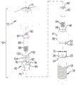
FIG. 1A is a top perspective view of a dental kit including a bridge abutment according to a first embodiment of the present invention;
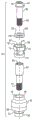
FIG. 1B is an exploded view of FIG. 1A;
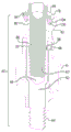
FIG. 1C is a longitudinal section taken along line I-I in FIG. 1A;
FIG. 1D is an exploded view of FIG. 1C;
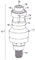
FIG. 1E is a top perspective view of a dental bridge abutment used in the dental device of FIG. 1A;
FIG. 1F is an exploded view of the diagram IE;
FIG. 1G is a longitudinal section of the drawing IE;
and (4) fig. 1H to 1K relate to a modification of the dental kit shown in fig. 1-2. 1A to 1G, wherein:
FIG. 1H is a top perspective view of the dental kit;
FIG. 1I is an exploded view of FIG. 1H;
FIG. 1J is a longitudinal section of FIG. 1H;
FIG. 1K is an exploded view of FIG. 1J;
FIG. 2A is a top perspective view of a dental kit including a dental bridge abutment according to a second embodiment of the present invention;
FIG. 2B is an exploded view of FIG. 2A;
FIG. 2C is a longitudinal section taken along line II-II in FIG. 2A;
FIG. 2D is an exploded view of FIG. 2C;
figure 2E is a top perspective view of a dental abutment used in the dental kit of figure AA;
FIG. 2F is an exploded view of FIG. 2E;
FIG. 2G is a longitudinal section of FIG. 2E;
FIG. 3A is a top perspective view of a dental kit including a dental abutment according to a modification of the second embodiment of the present invention;
FIG. 3B is an exploded view of FIG. 3 a;
FIG. 3C is a longitudinal section taken along line III-III in FIG. 3 a;
FIG. 3D is an exploded view of FIG. 3C;
FIG. 3E is a top perspective view of a dental bridge abutment used in the dental device of FIG. 3 a;
FIG. 3F is an exploded view of FIG. 3E;
FIG. 3G is a longitudinal section of FIG. 3E;
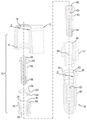
FIGS. 3H and 3I illustrate the dental kit example of FIG. 3a, demonstrating tolerance correction;
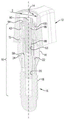
FIG. 4A is a top perspective view of a dental kit including a bridge abutment according to a third embodiment of the present invention;
FIG. 4B is the same as FIG. 4A, but with the tooth reconstruction elements cut away;
FIG. 4C is a longitudinal section taken along line IV-IV in FIG. 4A;
FIG. 4D is an enlarged view of the portion labeled IV in FIG. 4C;
FIG. 4E is a longitudinal section taken along line V-V in FIG. 4B;
FIG. 4F is an exploded view of FIG. 4E;
FIG. 4G is an exploded view of FIG. 4B;
FIG. 4H is an enlarged plan sectional view of an abutment used in the example shown in FIG. 4E;
FIG. 4I is a top perspective cut-away view of the abutment of FIG. 4H;
FIG. 4J illustrates the abutment of FIG. 4I with a threaded fastener articulated thereto;
FIG. 4K is a top perspective view of a dental bridge abutment used in the dental device of FIG. 4 a;
FIG. 4L is an exploded view of FIG. 4K;
FIG. 4M is a longitudinal sectional view of FIG. 4K;
FIG. 5A is a top perspective view of a dental reconstruction device including a support bar mounted on an abutment array according to an example of the present invention; and
fig. 5B is a plan view of fig. 5 a.
Detailed Description
Attention is first drawn to the drawings of fig. 1A to 1G, directed to a first embodiment of the present invention. The dental kit, generally designated 10, comprises a dental reconstruction element shown schematically, which in the example shown is part of a partial bridge 12. However, it should be appreciated that the tooth reconstruction elements may take any form, in whole or in part, of struts, micro struts, full/partial dentures, full or partial bridges, crowns, or any other similar tooth elements that constitute or support any type of dental prosthesis.
The dental reconstruction element 12 is provided with a hole 14 of nominal diameter D (fig. 1C and ID) having an annular groove 15 at its bottom, the purpose of which will become apparent hereinafter.
There is provided a dental implant 16 of known construction, the dental implant 16 comprising an external thread 18 for fitting into a cavity of a jaw bone (not shown) of an individual, and an internal thread 20 at a receiving bore 22 of an abutment, the nominal diameter Di being disposed at an apical end of the dental implant, and further wherein the dental implant comprises a tapered apical ring 24 having a smooth top edge 26. Furthermore, the dental abutment is provided with a polygonal (hexagonal in the shown example) head socket for fixing the dental implant within the jaw bone.
An abutment assembly 40 according to a first embodiment of the present invention is shown. From IE to 1G. The abutment assembly 40 comprises an abutment body 41 and a tubular reconstruction element support 42. The abutment body is tubular and is configured with a through abutment bore 46, the abutment bore 46 extending between a top (proximal) flat support end 48 and a bottom (distal) end, the bottom (distal) end being configured with a boss 50, the boss 50 having an outer diameter corresponding to Di of the abutment receiving bore 22 and further being configured with a polygonal portion 52 and a downward skirt portion 56. The arrangement is such that the boss 50 is shaped and dimensioned for snug receipt within the abutment receiving bore 22 and the skirt 56 rests on the tapered top ring 24 with the abutment surfaces thereby substantially eliminating movement between the elements.
The abutment bore 46 is further configured with an internal fastener shoulder 58 whereby the abutment body 41 can be coupled to the dental implant 16 by an implant fastener 62 configured with an externally threaded portion 64 (corresponding to the internal threads 20 at the abutment receiving bore 22) and a polygonal fastening sleeve 68 whereby the fixation of the abutment body 41 with the dental implant 16 is strong and substantially non-moving. Implant fastener 62 is further configured with internal threads 63 at its top.
The tubular reconstruction element holder 42 has a distal (bottom) flat seat end 70 bearing flush with the flat support end 48 of the abutment body 41 and is configured with a proximal anchor head portion 72, the proximal anchor head portion 72 being configured with four symmetrically arranged axially extending slots 76 extending away from an upper edge 78 of the reconstruction element holder 42. While in the illustrated example the slots are axially arranged, it will be appreciated that the slots may be helically arranged about the longitudinal axis of the reconstruction element holder 42, and as such, the reconstruction element holder 42 may be configured with one or more slots. The reconstruction element holder 42 is further configured with an internal tapered tip 84 extending axially through the head bore 82. One type of manipulation fastener, bolt 86, has a threaded portion 88 corresponding to the internal threads 63 of the implant fastener 62, and has a polygonal socket 90 for securing it and a radially extending annular manipulation shoulder 94.
The abutment assembly further includes a handwheel 100, the handwheel 100 configured with a top surface 102 and tapered sidewalls 104. When assembled, the steering wheel 100 is disposed within the tapered portion 84 of the reconstruction component holder 42, and the bottom surface of the steering shoulder 94 of the steering fastener 86 is flush with the top surface 102. As a particular example, top surface 102 of handwheel 100 and the bottom surface of handwheel 94 are flat.
This arrangement allows the fixed manipulation fasteners 86 to be used both to secure the reconstruction element support 42 to the abutment body 41 (by coupling to the implant fasteners 62) and to apply an axial force to the steering wheel 100, thereby creating an outward radial force that aligns the inner surface 84 of the reconstruction element holder, expanding the anchor head (i.e., segment) of the reconstruction element holder 42 against the inner wall surface of the bore 14 of the dental reconstruction element 12.
Thus, the arrangement disclosed above provides for compensating for positioning tolerances and inaccuracies between the dental implant 16 and the axis of the dental reconstruction element 12, wherein such tolerances may be located near the longitudinal axis ("Z-axis") or near the axis intersecting the longitudinal axis ("X-axis" and' Y-axis "). Such tolerances may occur due to measurement variations, manufacturing variations, and the like. Such tolerances may extend axially, i.e. along the longitudinal axis of the dental system, or in a plane intersecting said longitudinal axis.
Note that the manipulation fasteners 86 are thinner than the implant fasteners 62, and the reconstruction element support 42 may be made of the same material as the abutment body 41 or a different material with different mechanical properties. Further, it should be appreciated that the outer surface of the anchor head portion 72 of the reconstruction element holder 42 may be smooth, as shown in the illustrated example, or may be surface treated to improve engagement with the inner wall surface of the bore 14 of the tooth reconstruction element 12. For example, such weld overlays may be serrations, knurls, axial/annular ridges, axial/annular grooves, rough weld overlays, and the like. Such configurations may be applied to any of the examples and embodiments disclosed herein.
Returning to the assembled dental kit 10, a sealing ring (not shown), such as an elastomeric O-ring, a stainless steel ring, or any other material ring, may be installed in an annular groove 15 within the bore 14 of the dental reconstruction element 12 such that, in the assembled position, the sealing ring abuts an outer surface of the abutment body 41 adapted to eliminate or substantially reduce ingress of saliva and food into the space extending between the bore of the dental reconstruction element and the outer surface of the abutment body. However, the use of a seal ring may sometimes be avoided.
Referring to fig. 1H to 1k, according to one aspect of the present invention, a modification of a dental kit 43 is shown, wherein the significant difference is the shape of an abutment body 45, which abutment body 45 is adapted to be mounted on a dental implant 47 configured with an external polygonal head.
Thus, the dental implant 47 is provided with an external polygonal head 49 protruding from the top surface 51 and with an internally threaded hole 53. Next, the abutment body 45 is configured with a through abutment hole 55, the abutment hole 55 having an internal fastener shoulder 57 and a bottom surface 79 located above the head receiving space 59.
The other components of the dental kit 43 are similar to those disclosed in connection with the example of fig. 4. 1a to 1G, wherein the abutment assembly 61 further comprises implant fasteners 67 for connecting the abutment body 45 to the dental implant 47 through the abutment holes 55, a tubular reconstruction element holder 69 (substantially identical to the tubular reconstruction element holder 42) and hinged to the abutment body 45 by a steering fastener bolt 71 through a steering wheel 73.
In the assembled position (fig. 1H and 1J), the abutment body 45 is secured to the dental implant 47 with the bottom surface 79 flush with the surface 51 and the outer polygonal head 49 of the dental implant 47 located within the head receiving space 59. After tightening the implant fasteners 67, the reconstruction element holder 69 is positioned on the abutment body 45 and, once the dental reconstruction element (not shown) is placed thereon, the fastener bolt 71 is manipulated by tightening, thereby setting the exact true position of the dental reconstruction element thereon.
In both embodiments of fig. 1A to 1k, the support 41; 45 may be coupled to the dental implant by a separate implant fastener 62; 67, however, we turn now to the embodiment shown in the figures. In fig. 2A to 2G, a dental implant is illustrated in which the abutment body may be coupled to the dental implant by a unitary implant fastener. For clarity, in the examples of the figures below. 2A to 2G, similar to the elements in fig. 1a to 1G, are designated with similar reference numerals but shifted by 100.
The dental device of fig. 2, generally designated 110, includes a dental reconstruction element shown schematically, which in the example shown is part of a partial bridge 112.
The tooth reconstruction elements 112 are configured with a bore 114 having a nominal diameter D (fig. 2C and 2D) with an annular groove 115 at the bottom for a purpose similar to that disclosed in connection with the previous examples.
A dental implant 116 of known construction is provided, the dental implant 116 comprising an external thread 118 for mounting in a cavity of a jaw bone (not shown) of an individual, and an internal thread 120, the internal thread 120 being located at an abutment receiving hole 122, the nominal diameter of which is configured at an apical end of the dental implant, and further wherein the dental implant comprises a tapered apical ring 124 having a smooth top edge 126. The dental abutment is provided with a polygonal head-seat for fixing the dental implant in the jaw bone.
An abutment assembly 140 according to a second embodiment of the invention is shown: 2E to 2G. The abutment assembly 140 includes an abutment body 141 and a tubular reconstruction element support 142. Abutment body 141 is configured at its distal (bottom) end with an integral solid threaded rod 143 having an outer nominal diameter corresponding to the outer nominal diameter of abutment-receiving threaded bore 122. Further, the dental body 141 is provided with an internally threaded hole 145 at its top and has a polygonal fastening sleeve 168.
Implant 141 has a top (proximal) flat support end 148 and a bottom (distal) end configured with a boss 150, the boss 150 having an outer diameter corresponding to the inner diameter of the abutment receiving bore 122 and optionally configured with a tapered portion 156. The arrangement is such that the boss 150 is shaped and dimensioned for snug receipt within the abutment receiving bore 122, and the tapered portion 156 rests on the tapered top ring 124 with an abutment surface, thereby substantially eliminating movement between the elements, once the threaded stem 143 is secured within the threaded receiving bore 122, thereby securing the abutment body 141 with the dental implant 116 substantially immovable.
The tubular reconstruction element holder 142 has a distal (bottom) flat seat end 170 bearing flush with the flat seat end 148 of the abutment body 141 and is configured with a proximal anchor head portion 172, the proximal anchor head portion 172 being configured with four symmetrically arranged, axially extending slots 176 extending away from an upper edge 178 of the reconstruction element holder 142. While in the illustrated example the slots are arranged axially, it will be appreciated that the slots may be helically arranged about the longitudinal axis of the reconstruction element support 142, and likewise, the number of slots may vary.
The reconstruction element holder 142 is further configured with an internal tapered top section 184 extending axially through the head bore 182. A manipulation fastener, bolt 186, has an externally threaded portion 188 corresponding to the internal threads 145 of the abutment body 141, and has a polygonal socket 190 for securing it, and a radially extending annular manipulation shoulder 194 having a bottom surface 195.
Abutment assembly 140 further includes a handwheel 101, handwheel 101 configured with a top surface 103 and tapered (bottom) side walls 105. When assembled, the handwheel 101 is disposed within the tapered portion 184 of the reconstruction component holder 142 with the bottom surface 195 of the manipulation shoulder 194 of the manipulation fastener 186 flush with the top surface 103. In this particular example, the upper surface of the steering wheel and the bottom surface of the steering shoulder are also flat.
This arrangement allows the tightening of the manipulation fasteners 186 to both secure the reconstruction element holder 142 to the abutment body 141 and to apply an axial force to the manipulation disk 101, which in turn generates an outward radial force, which aligns the inner surface 184 of the reconstruction element holder, expanding the anchor head (i.e., segment) of the reconstruction element holder 142 and abutting the inner wall surface of the bore 114 of the dental reconstruction element 112.
Similar to the previous example, the arrangement disclosed above thus provides for compensating for positioning tolerances and inaccuracies between the axes of the dental implant 116 and the dental reconstruction element 112, wherein such tolerances may be located near the longitudinal axis ("Z-axis") or about axes intersecting said longitudinal axis ("X-axis" and' Y-axis "). Such tolerances may occur due to measurement variations, manufacturing variations, and the like. Such tolerances may extend axially, i.e. along the longitudinal axis of the dental system, or in a plane intersecting said longitudinal axis.
Similarly, it will be appreciated that the outer surface of the anchor head portion 172 of the reconstruction element holder 142 may be smooth, as in the illustrated example, or may be surface treated to improve engagement with the inner wall surface of the aperture 114 of the tooth reconstruction element 112. For example, such surfaces may be serrations, knurls, axial/annular ridges, axial/annular grooves, roughened surfaces, and the like.
Attention is now further directed to fig. 3A to 3G, which fig. 3A to 3G relate to a modification of the first embodiment shown in fig. 1A to 1G. For simplicity, like elements are designated with like reference numerals, with an "indicator" added.
In fact, the dental kit 10' is similar to that disclosed in the example of fig. 1A to 1G, but has a different design with respect to the abutment body 41' and the dental implant 16', respectively. Thus, the references in the following examples focus on different elements.
The dental kit 10 'thus comprises a dental reconstruction element shown schematically, which in the example shown is part of a partial bridge 12', which bridge 12 'is provided with a hole 14' having a nominal diameter.
A dental implant 16' includes an external thread 18' for installation into a cavity of an individual's jaw bone (not shown), and an internal thread 20', 20' having a nominal diameter Di at an abutment receiving hole 22' configured at the apical end of the dental implant, the top head 123 having a smooth top edge 26 '.
The abutment assembly 40' includes an abutment body 41' and a tubular reconstruction element support 42', which is similar to and references back to the reconstruction element support 42 in the example of fig. 1A-1G.
The abutment body 41 'is tubular and is configured with a through abutment bore 46' extending between a top (proximal) flat support end 48 'and a bottom (distal) end, the bottom (distal) end being configured with a boss 50', the boss 50 'having an outer diameter corresponding to Di of the abutment receiving bore 22', and further being configured with a gripping portion 52 'and a tapered portion 56' configured for snug and mating receipt within the abutment receiving bore 22 'of the dental implant 16'. The arrangement is such that the boss 50 'is shaped and dimensioned for snug receipt within the abutment receiving bore 22', with the tapered portion 56 'contacting the abutment surface of the bore 22', thereby substantially eliminating movement between the elements.
The abutment bore 46 'of the abutment body 41' is further configured with an internal fastener shoulder 58', whereby the abutment body 41' can be coupled to the dental implant 16 '(corresponding to the internal threads 20' at the abutment receiving bore 22 ') and the polygonal fastening socket 68' by an implant fastener 62 'configured with an external threaded portion 64', wherein the abutment body 41 'is fastened with the dental implant 16' and is strong and substantially non-moving. Implant fastener 62 'is further configured with internal threads 63' at its top.
The manipulation fastener, i.e., bolt 86', has a threaded portion 88' corresponding to the internal threads 63 'of the implant fastener 62', and has a polygonal socket 90 'for fastening it, and a radially extending annular manipulation shoulder 94'.
The abutment assembly also includes a handwheel 100' configured with a top surface 102' and tapered sidewalls 104 '. When assembled, the steering wheel 100 'is disposed within the tapered portion 84' of the reconstruction element holder 42 'with the bottom surface of the steering shoulder 94' of the steering fastener 86 'flush with the top surface 102'.
This arrangement allows the fixed manipulation fasteners 86' to both secure the reconstruction element holder 42' to the abutment body 41' (by coupling to the implant fasteners 62') and apply an axial force to the steering wheel 100' thereby creating an outward radial force, aligning the inner surface 84' of the reconstruction element holder, expanding the anchor head (i.e., segment) of the reconstruction element holder 42' and abutting the inner wall surface of the bore 14' of the dental reconstruction element 12 '.
Thus, the arrangement disclosed above provides for compensating for positioning tolerances and inaccuracies between the dental implant 16 and the axis of the dental reconstruction element 12', where such tolerances may be located near the longitudinal axis ("Z-axis") or near the axis intersecting the longitudinal axis ("X-axis" and "Y-axis"). Such tolerances may occur due to measurement variations, manufacturing variations, and the like. Such tolerances may extend axially, i.e. along the longitudinal axis of the dental system, or in a plane intersecting said longitudinal axis.
Further, it should be appreciated that the outer surface of the anchor head portion 72 'of the reconstruction element holder 42' may be smooth, as shown in the illustrated example, or may be surface treated to improve engagement with the inner wall surface of the bore 14 'of the tooth reconstruction element 12'. For example, such weld overlays may be serrations, knurls, axial/annular ridges, axial/annular grooves, rough weld overlays, and the like. Such configurations may be applied to any of the examples and embodiments disclosed herein.
Similarly, a sealing ring (not shown) may be inserted into the annular groove 15 'of the tooth reconstruction element 12 such that in the assembled position the sealing ring abuts the outer surface of the abutment body 41' and is adapted to eliminate or substantially reduce ingress of saliva and food into the space extending between the tooth reconstruction element bore and the outer surface of the abutment body.
In fig. 3H, a dental apparatus according to the example of fig. 3A to 3G is shown, wherein the dental implant 16 "and the associated abutment 48" and the reconstruction element holder 42 "extend along a longitudinal axis X", while the dental reconstruction element 12 "is arranged at an angle Y", with an angle m as described above, "between them, but set in place by the reconstruction element support 42".
However, an example of correcting tolerance problems is shown in fig. 31, which shows a dental kit according to the example of fig. 3A to 3G, wherein the dental implant 16 "' and the associated base tooth body 48" ' and the reconstruction element holder 42 "' extend along a longitudinal axis X" ', while the dental reconstruction element 12 "' is arranged around it at an angle Y" ' with an angle i "' in between, and wherein the dental reconstruction element 12" ' is at a distance H from the apex of the polygonal socket 90 "' of the implant fastener 62" ', however, as described above, set in place by the reconstruction element holder 42 "'.
Another embodiment is disclosed in fig. 4A to 4L, which is generally designated 210 for an adjustable dental kit, and for clarity, in the following examples like elements in fig. 1A to 1G are designated with like reference numerals but shifted by 200.
The dental kit 210 comprises a dental reconstruction element, which in the example shown is part of a partial bridge 212. However, it should be appreciated that the tooth reconstruction elements may take any form, in whole or in part, of struts, micro struts, full/partial dentures, full or partial bridges, crowns, or any other similar tooth elements that constitute or support any type of dental prosthesis.
The tooth reconstruction elements 212 are provided with holes 214 of nominal diameter D, the bottom of which has an annular groove 215, the purpose of which will become apparent hereinafter.
A dental implant 216 of known construction is provided, the dental implant 216 including an external thread 218 for mounting into a cavity of an individual's jaw bone (not shown), and an internal thread 220 at an abutment receiving hole 222 of nominal diameter, further wherein the dental implant includes a tapered top ring 224 having a smooth top edge 226 and a polygonal head sleeve 223 for securing the dental implant 216 within the jaw bone.
An abutment assembly 240 in accordance with various embodiments of the present invention is shown in fig. 4E and 4F. The abutment assembly 240 includes an abutment body 241 and a tubular reconstruction element holder 242. The abutment body 241 is generally tubular, configured with a longitudinal second axis X2, configured with a through abutment aperture 246, and configured at a distal end (bottom) with a polygonal boss 250 configured to be received within the polygonal head seat 223 of the dental abutment 216 at discrete angular increments, depending, of course, on the number of faces of the polygonal socket 223 and the number of faces of the polygonal boss 250.
According to a specific example, the outer polygonal boss 250 of the abutment body 241 is a 12-sided polygon, while the polygonal socket 223 of the dental implant 216 is a 6-sided polygon, thereby imparting an axial angular increment of 30 ° on the dental implant. However, other combinations of polygonal bosses and polygonal sockets may be employed, such as 8-sided polygonal bosses with 8-sided polygonal sockets, 8-sided polygonal bosses with 16-sided polygonal sockets, 6-sided polygonal bosses with 6-sided polygonal sockets, and so forth.
The abutment body 241 is further configured with a tapered portion facing the skirt 256 such that the boss 250 is shaped and dimensioned for snug receipt within the abutment receiving bore 222, the skirt 256 being seated within a corresponding tapered portion within the top ring 224 of the dental implant 216, thereby substantially eliminating movement between the components once coupled.
The abutment bore 246 is further configured with an internal fastener shoulder 258 whereby the abutment body 241 can be coupled to the dental implant 216 by an implant fastener 262 configured with an externally threaded portion 264 (corresponding to the internal threads 220 at the abutment receiving bore 222) and a polygonal fastening sleeve 268 whereby the abutment body 241 is secured with the dental implant 216 firmly and substantially without movement. The implant fasteners 262 may be fastened through openings 265 configured at the plateau surface of the abutment body 241, whereby the abutment bodies 241 are coupled to each other about the longitudinal second axis X2.
The abutment 241 is further provided with a tubular projection 271, which projection 271 extends upwardly from a plane 267 and extends along a first axis, said tubular projection 271 being provided with an internal thread 263, wherein the mat and a second axis X2 intersect each other in an imaginary plane, wherein the angle a between the first and second axes is in the range of about 3 ° to 8 °, typically about 5 °.
The tubular reconstruction element holder 242 has a distal (bottom) flat seat end 70 which, in the assembled position, is flush with a flat face 267 of the abutment body 241 and is configured with a proximal anchor head portion 272, the proximal anchor head portion 272 being configured with four symmetrically arranged, axially extending slots 276 extending away from an upper edge 278 of the reconstruction element support 242. Although in the illustrated example the slots are arranged axially, it will be appreciated that the slots may be arranged helically about the longitudinal axis of the reconstruction element support 242, and likewise, the number of slots may vary.
The reconstruction element holder 42 is further configured with an internal tapered top portion 284 extending axially through the head bore 282. One type of manipulation fastener, bolt 286, has a threaded portion 288 corresponding to the internal threads 263 of the implant fastener 262, and has a polygonal socket 290 for securing thereto and a radially extending annular manipulation shoulder 294.
Abutment assembly 240 further includes a handwheel 201, handwheel 201 configured with a flat top surface 202 and tapered sidewalls 204. When assembled, the steering wheel 201 is disposed within the tapered portion 284 of the reconstruction element holder 242, and the bottom surface of the steering shoulder 294 of the steering fastener 286 is flush with the flat top surface 202.
This arrangement allows the fixed manipulation fasteners 286 to both secure the reconstruction element support 242 to the abutment body 241 (by coupling to the implant fasteners 262) and to apply an axial force to the steering wheel 201, which in turn generates an outwardly directed radial force, which aligns the inner surface 284 of the reconstruction element holder, causing the anchor head (i.e., segment) of the reconstruction element holder 242 to expand and abut against the inner wall surface of the bore 214 of the dental reconstruction element 212.
Thus, the arrangement disclosed above provides for compensating for positioning tolerances and inaccuracies between the axes of the dental implant 216 and the dental reconstruction element 212, wherein such tolerances may be located around the longitudinal axis ("Z-axis") or around axes intersecting said longitudinal axis ("X-axis" and' Y-axis "). Such tolerances may occur due to measurement variations, manufacturing variations, and the like. Such tolerances may extend axially, i.e. along the longitudinal axis of the dental system, or in a plane intersecting said longitudinal axis.
The angular offset A between the first and second axes X2, along with the discrete, incremental angular positioning of the abutment assembly 240 relative to the longitudinal axis of the dental abutment 216, provides a unique structure that provides support for the dental reconstruction elements in a variety of settings, regardless of the preset axial alignment of the dental implant, yet in a robust manner, further providing the ability to overcome three-dimensional tolerances.
Further, it should be appreciated that the outer surface of the anchor head portion 272 of the reconstruction element support 242 is surface treated to improve engagement with the inner wall surface of the bore 14 of the tooth reconstruction element 12. Such surfaces in this example comprise annular ridges. Although it could be serrations, knurls, axial/annular ridges, axial/annular grooves, roughened surfaces, etc.
Returning to the assembled dental kit 210, a sealing ring (not shown), such as an elastomeric O-ring or metal ring, may be mounted in an annular groove 215 within the bore 214 of the dental reconstruction element 212 such that in the assembled position the sealing ring abuts the outer surface of the abutment body 241, adapted to eliminate or substantially reduce the ingress of saliva and food into the space extending between the bore of the dental reconstruction element and the outer surface of the abutment body.
Fig. 5A and 5B illustrate a dental kit 310, the dental kit 310 including dental reconstruction elements that are support rods 312 mounted on 5 dental implants 316; to 316 v. Note that at least some of the dental implants 316; the voltages to 316v are not arranged parallel, sometimes on multiple axes. For example, a dental implant 316; the angular offset at angles bi and b2, relative to the dental implant 316; (ii) a The dental implant 316iv is angularly offset relative to the dental implant 316v at angles g and Y2. Such angular misalignment, as well as tolerances and inaccuracies that exist between the axes of the dental implant 316; according to any of the embodiments disclosed herein, 316v and tooth reconstruction elements 312, such as axial (elevation) gap h (fig. 5B), may be overcome by the tooth base (such tolerances and inaccuracies may occur due to measurement variations, manufacturing variations, etc.).