CN114034032A - Heat recovery system and method for high-temperature gas cooled reactor in low-load operation stage - Google Patents
Heat recovery system and method for high-temperature gas cooled reactor in low-load operation stage Download PDFInfo
- Publication number
- CN114034032A CN114034032A CN202111315471.8A CN202111315471A CN114034032A CN 114034032 A CN114034032 A CN 114034032A CN 202111315471 A CN202111315471 A CN 202111315471A CN 114034032 A CN114034032 A CN 114034032A
- Authority
- CN
- China
- Prior art keywords
- steam
- pipeline
- water separator
- deaerator
- communicated
- Prior art date
- Legal status (The legal status is an assumption and is not a legal conclusion. Google has not performed a legal analysis and makes no representation as to the accuracy of the status listed.)
- Pending
Links
Images
Classifications
-
- F—MECHANICAL ENGINEERING; LIGHTING; HEATING; WEAPONS; BLASTING
- F22—STEAM GENERATION
- F22D—PREHEATING, OR ACCUMULATING PREHEATED, FEED-WATER FOR STEAM GENERATION; FEED-WATER SUPPLY FOR STEAM GENERATION; CONTROLLING WATER LEVEL FOR STEAM GENERATION; AUXILIARY DEVICES FOR PROMOTING WATER CIRCULATION WITHIN STEAM BOILERS
- F22D1/00—Feed-water heaters, i.e. economisers or like preheaters
- F22D1/50—Feed-water heaters, i.e. economisers or like preheaters incorporating thermal de-aeration of feed-water
-
- F—MECHANICAL ENGINEERING; LIGHTING; HEATING; WEAPONS; BLASTING
- F22—STEAM GENERATION
- F22B—METHODS OF STEAM GENERATION; STEAM BOILERS
- F22B37/00—Component parts or details of steam boilers
- F22B37/02—Component parts or details of steam boilers applicable to more than one kind or type of steam boiler
- F22B37/26—Steam-separating arrangements
-
- F—MECHANICAL ENGINEERING; LIGHTING; HEATING; WEAPONS; BLASTING
- F22—STEAM GENERATION
- F22B—METHODS OF STEAM GENERATION; STEAM BOILERS
- F22B37/00—Component parts or details of steam boilers
- F22B37/02—Component parts or details of steam boilers applicable to more than one kind or type of steam boiler
- F22B37/42—Applications, arrangements, or dispositions of alarm or automatic safety devices
- F22B37/44—Applications, arrangements, or dispositions of alarm or automatic safety devices of safety valves
-
- F—MECHANICAL ENGINEERING; LIGHTING; HEATING; WEAPONS; BLASTING
- F22—STEAM GENERATION
- F22B—METHODS OF STEAM GENERATION; STEAM BOILERS
- F22B37/00—Component parts or details of steam boilers
- F22B37/02—Component parts or details of steam boilers applicable to more than one kind or type of steam boiler
- F22B37/48—Devices for removing water, salt, or sludge from boilers; Arrangements of cleaning apparatus in boilers; Combinations thereof with boilers
- F22B37/54—De-sludging or blow-down devices
-
- G—PHYSICS
- G21—NUCLEAR PHYSICS; NUCLEAR ENGINEERING
- G21C—NUCLEAR REACTORS
- G21C15/00—Cooling arrangements within the pressure vessel containing the core; Selection of specific coolants
- G21C15/16—Cooling arrangements within the pressure vessel containing the core; Selection of specific coolants comprising means for separating liquid and steam
-
- G—PHYSICS
- G21—NUCLEAR PHYSICS; NUCLEAR ENGINEERING
- G21D—NUCLEAR POWER PLANT
- G21D1/00—Details of nuclear power plant
-
- G—PHYSICS
- G21—NUCLEAR PHYSICS; NUCLEAR ENGINEERING
- G21D—NUCLEAR POWER PLANT
- G21D1/00—Details of nuclear power plant
- G21D1/02—Arrangements of auxiliary equipment
-
- Y—GENERAL TAGGING OF NEW TECHNOLOGICAL DEVELOPMENTS; GENERAL TAGGING OF CROSS-SECTIONAL TECHNOLOGIES SPANNING OVER SEVERAL SECTIONS OF THE IPC; TECHNICAL SUBJECTS COVERED BY FORMER USPC CROSS-REFERENCE ART COLLECTIONS [XRACs] AND DIGESTS
- Y02—TECHNOLOGIES OR APPLICATIONS FOR MITIGATION OR ADAPTATION AGAINST CLIMATE CHANGE
- Y02E—REDUCTION OF GREENHOUSE GAS [GHG] EMISSIONS, RELATED TO ENERGY GENERATION, TRANSMISSION OR DISTRIBUTION
- Y02E30/00—Energy generation of nuclear origin
- Y02E30/30—Nuclear fission reactors
Landscapes
- Engineering & Computer Science (AREA)
- Physics & Mathematics (AREA)
- General Engineering & Computer Science (AREA)
- Thermal Sciences (AREA)
- Mechanical Engineering (AREA)
- Plasma & Fusion (AREA)
- High Energy & Nuclear Physics (AREA)
- Engine Equipment That Uses Special Cycles (AREA)
Abstract
The invention provides a heat recovery system and a heat recovery method for a high-temperature gas cooled reactor in a low-load operation stage, which belong to the technical field of nuclear power and comprise the following steps: a steam generator; the inlet of the steam-water separator is communicated with the outlet of the steam generator; the top outlet of the steam-water separator is communicated with the inlets of the condenser and the deaerator through a tee joint; the bottom outlet of the steam-water separator is communicated with the inlets of the condenser and the deaerator through a tee joint; the outlet of the condenser is communicated with the deaerator; a deaerator; according to the heat recovery system in the high-temperature gas-cooled reactor low-load operation stage, the drainage water and the steam in the steam-water separator are recovered into the deaerator, and the heat generated by the reactor is recycled, so that the auxiliary steam consumption of the electric boiler for the deaerator is reduced, the energy recovery and utilization are realized, and a large amount of electric charges are saved.
Description
Technical Field
The invention relates to the technical field of nuclear power, in particular to a heat recovery system and a heat recovery method for a high-temperature gas cooled reactor in a low-load operation stage.
Background
The low-load operation time of the high-temperature gas cooled reactor is about 4 months in the debugging stage, and the low-load operation time of the subsequent unit is about 8 days each time. When the unit operates at low load, the flow rate of the feed water is 130t/h, the temperature is 160 ℃, and at the moment, the secondary steam extraction parameter is low, so that the feed water in the deaerator cannot be heated to the required temperature. At the moment, the auxiliary steam generated by the electric boiler is mainly used for heating, and the electric boiler consumes more than fifty million yuan in electricity only in the debugging stage.
On the other hand, the feed water absorbs the heat generated by the reactor in the steam generator, the generated steam enters a steam-water separator of the reactor starting and stopping system, after steam-water separation, the high-temperature drain water is discharged into the condenser through a bottom drain pipe, the high-temperature steam enters the condenser through a bypass valve, and the heat in the steam-water separator is cooled by circulating water and then discharged into the sea, so that the heat is not effectively utilized, and the heat waste is caused.
Therefore, when the existing mode is adopted for low-power operation, energy is not effectively utilized, and a large amount of energy is wasted.
Disclosure of Invention
Therefore, the technical problem to be solved by the present invention is to overcome the defect that energy is not effectively utilized when the high temperature gas cooled reactor in the prior art operates in the existing mode, which results in a large amount of energy waste, thereby providing a heat recovery system and method for the high temperature gas cooled reactor in the low load operation stage.
In order to solve the above technical problem, the present invention provides a heat recovery system at a low load operation stage of a high temperature gas cooled reactor, including:
the outlet of the steam generator is communicated with the inlet of the steam turbine; the outlet of the steam turbine is communicated with the inlet of the condenser;
the inlet of the steam-water separator is communicated with the outlet of the steam generator; the top outlet of the steam-water separator is communicated with the steam inlets of the condenser and the deaerator through a tee joint; the bottom outlet of the steam-water separator is communicated with the drainage inlets of the condenser and the deaerator through a tee joint;
the outlet of the condenser is communicated with the deaerator;
and the outlet of the deaerator is communicated with the steam generator.
Preferably, an outlet of the steam generator is communicated with one end of a second pipeline; the other end of the second pipeline is communicated with the steam turbine through a first branch pipeline and is communicated with the condenser through a second branch pipeline;
a third stop valve is arranged on the second pipeline; the first branch pipeline is provided with a steam turbine air inlet valve group; and a bypass valve is arranged on the second branch pipeline.
As a preferred scheme, the steam generator is communicated with the steam-water separator through a first pipeline and a bypass pipeline which are arranged in parallel; a first isolating valve and a first regulating valve are arranged on the first pipeline; and a second stop valve and a first temperature and pressure reducing valve are arranged on the bypass pipeline.
As a preferred scheme, a top outlet of the steam-water separator is communicated with the condenser through a third pipeline; the third pipeline is communicated with the deaerator through a fifth pipeline; and a second temperature and pressure reducing device and a fifth stop valve are arranged on the fifth pipeline.
As a preferred scheme, a bottom outlet of the steam-water separator is communicated with the condenser through a fourth pipeline; a second regulating valve is arranged on the fourth pipeline; the fourth pipeline is communicated with the deaerator through a sixth pipeline; and a third regulating valve is arranged on the sixth pipeline.
As a preferred scheme, an outlet of the condenser is communicated with the deaerator through an eighth pipeline; the outlet of the deaerator is communicated with the steam generator through a ninth pipeline; and a main water feeding pump is arranged on the ninth pipeline.
The invention also provides a heat recovery method in the low-load operation stage of the high-temperature gas cooled reactor,
in a first time period, the drained water in the steam-water separator enters a condenser; steam in the steam-water separator enters a deaerator;
in a second time period, the hydrophobic water in the steam-water separator enters a deaerator; steam in the steam-water separator enters a deaerator;
in a third time period, steam in the steam-water separator enters the deaerator; hydrophobic water in the steam-water separator enters a deaerator;
in a fourth time period, part of steam in the steam-water separator enters the condenser, and part of steam enters the deaerator; the drained water in the steam-water separator enters a condenser;
and in a fifth time period, steam in the steam-water separator enters the deaerator, and drain water in the steam-water separator enters the condenser.
As a preferred scheme, in a third time period, when the pressure in the steam-water separator reaches the rated operation pressure of 0.7Mpa of the deaerator, putting a second temperature and pressure reducing device into the deaerator, and controlling the steam pressure entering the deaerator not to exceed 0.7 Mpa; when the pressure in the steam-water separator reaches 1.2Mpa, the fourth stop valve is opened, part of steam enters the second pipeline and enters the condenser through the bypass valve, and the pressure in the steam-water separator is controlled not to exceed 1.2 Mpa.
According to the preferable scheme, in the fourth time period, steam in the steam generator enters the steam-water separator through the bypass pipeline, the steam pressure in the steam-water separator is controlled to be 5Mpa through the first temperature and pressure reducing device, and the steam is subjected to secondary temperature and pressure reduction through the second temperature and pressure reducing device and then is introduced into the deaerator to be heated and deaerated.
In a fifth time period, part of steam in the steam generator passes through the steam-water separator, is subjected to two-stage temperature and pressure reduction and then flows to the deaerator, and the other part of steam enters the steam turbine.
The technical scheme of the invention has the following advantages:
1. the invention provides a heat recovery system for a high-temperature gas cooled reactor in a low-load operation stage, which comprises: the system comprises a steam generator, a steam-water separator, a condenser, a steam turbine and a deaerator; through the optimization and transformation of a start-stop reactor system, a top outlet and a bottom outlet of a steam-water separator are respectively communicated with a deaerator; at the low-load operation stage of the high-temperature gas cooled reactor, the drainage and steam in the steam-water separator are recovered to the deaerator, and the heat generated by the reactor is recycled, so that the auxiliary steam consumption of the electric boiler required to be provided for the deaerator is reduced, the energy recycling is realized, and a large amount of electric charges are saved.
2. According to the heat recovery system in the low-load operation stage of the high-temperature gas-cooled reactor, the bypass pipeline of the steam-water separator inlet pipe, the fifth pipeline from the top outlet of the steam-water separator to the deaerator, the sixth pipeline from the bottom outlet of the steam-water separator to the deaerator, and related valves and temperature and pressure reducing devices on the pipelines are additionally arranged on the original system, so that drainage and steam in the steam-water separator are recovered into the deaerator, the reconstruction cost is low, and only part of pipelines and equipment are added.
3. According to the heat recovery system in the low-load operation stage of the high-temperature gas-cooled reactor, the temperature and pressure reduction devices are arranged on the bypass pipeline and the fifth pipeline, so that high-temperature and high-pressure steam is subjected to two-stage temperature and pressure reduction, the operation is safe and reliable, the requirements on the performance of the temperature and pressure reduction devices are low, the equipment cost is low, and the investment income is high.
Drawings
In order to more clearly illustrate the embodiments of the present invention or the technical solutions in the prior art, the drawings used in the description of the embodiments or the prior art will be briefly described below, and it is obvious that the drawings in the following description are some embodiments of the present invention, and other drawings can be obtained by those skilled in the art without creative efforts.
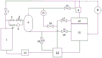
Fig. 1 is a schematic structural diagram of a labeled valve body of the heat recovery system in the low-load operation stage of the high temperature gas cooled reactor.
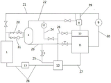
Fig. 2 is a schematic structural diagram of a labeled pipeline of the heat recovery system in the low-load operation stage of the high temperature gas cooled reactor of the invention.
Description of reference numerals:
1. a steam generator; 2. a first shut-off valve; 3. a first regulating valve; 4. a steam-water separator; 5. a second stop valve; 6. a first temperature and pressure reducing device; 7. a third stop valve; 8. a steam inlet valve bank of the steam turbine; 9. a bypass valve; 10. a steam turbine; 11. a condenser; 12. a deaerator; 13. a main feed pump; 14. a fourth stop valve; 15. a second temperature and pressure reducing device; 16. a fifth stop valve; 17. a sixth stop valve; 18. a second regulating valve; 19. a third regulating valve; 20. a first pipeline; 21. a second pipeline; 22. a third pipeline; 23. a fourth pipeline; 24. a fifth pipeline; 25. a sixth pipeline; 26. a seventh pipeline; 27. an eighth pipeline; 28. a ninth conduit; 29. a first branch line; 30. a second branch line; 31. a bypass line.
Detailed Description
The technical solutions of the present invention will be described clearly and completely with reference to the accompanying drawings, and it should be understood that the described embodiments are some, but not all embodiments of the present invention. All other embodiments, which can be derived by a person skilled in the art from the embodiments given herein without making any creative effort, shall fall within the protection scope of the present invention.
In the description of the present invention, it should be noted that the terms "center", "upper", "lower", "left", "right", "vertical", "horizontal", "inner", "outer", etc., indicate orientations or positional relationships based on the orientations or positional relationships shown in the drawings, and are only for convenience of description and simplicity of description, but do not indicate or imply that the device or element being referred to must have a particular orientation, be constructed and operated in a particular orientation, and thus, should not be construed as limiting the present invention.
In the description of the present invention, it should be noted that, unless otherwise explicitly specified or limited, the terms "mounted," "connected," and "connected" are to be construed broadly, e.g., as meaning either a fixed connection, a removable connection, or an integral connection; can be mechanically or electrically connected; they may be connected directly or indirectly through intervening media, or they may be interconnected between two elements. The specific meanings of the above terms in the present invention can be understood in specific cases to those skilled in the art.
In addition, the technical features involved in the different embodiments of the present invention described below may be combined with each other as long as they do not conflict with each other.
The invention provides a heat recovery system for a high-temperature gas cooled reactor in a low-load operation stage, which comprises: the system comprises a steam generator, a steam-water separator, a condenser, a steam turbine, a deaerator and a feed water pump; through opening the optimization transformation who stops the heap system, add catch water inlet pipe bypass pipeline on original system, catch water drainage to oxygen-eliminating device pipeline, catch water export to second grade extraction of steam pipeline and relevant valve, temperature and pressure reduction device, at high temperature gas cooled reactor low-load operation stage, retrieve drainage and steam in the catch water to the oxygen-eliminating device in, carry out recycle with the heat that the reactor produced, the auxiliary steam quantity that electric boiler need provide for the oxygen-eliminating device has been reduced, a large amount of charges of electricity have been practiced thrift.
As shown in fig. 1 and 2, the outlet of the steam generator 1 is arranged in communication with a first pipe 20 and a second pipe 21; the first pipeline 20 is provided with a first stop valve 2 and a first regulating valve 3, and the other end of the first pipeline 20 is communicated with the steam-water separator 4; the second pipeline 21 is provided with a third stop valve 7; the other end of the second pipeline 21 is communicated with the steam turbine 10 through a first branch pipeline 29 and communicated with the condenser 11 through a second branch pipeline 30; a steam turbine inlet valve group 8 is arranged on the first branch pipeline 29; a bypass valve 9 is arranged on the second branch pipeline 30; a bypass pipeline 31 is connected with the first pipeline 20 in parallel, and a second stop valve 5 and a first temperature and pressure reducing device 6 are arranged on the bypass pipeline 31;
the top outlet of the steam generator 1 is communicated with one end of a third pipeline 22, and the other end of the third pipeline 22 is communicated with the rear end of a third stop valve 7 of the second pipeline 21; a fourth shut-off valve 14 is arranged on the third pipeline 22;
the steam turbine high-pressure cylinder exhaust steam (secondary extraction steam) is communicated with the deaerator 12 through a seventh pipeline 26, and a sixth stop valve 17 is arranged on the seventh pipeline 26; the third pipeline 22 is communicated with the seventh pipeline 26 through a fifth pipeline 24, specifically, one end of the fifth pipeline 24 is communicated with the front end position of the fourth stop valve 14 of the third pipeline 22, and the other end is communicated with the rear end position of the sixth stop valve 17 of the seventh pipeline 26; the fifth pipeline 24 is provided with a second temperature and pressure reducing device 15 and a fifth stop valve 16;
the bottom outlet of the steam-water separator 4 is communicated with the condenser 11 through a fourth pipeline 23, and a second regulating valve 18 is arranged on the fourth pipeline 23; the front end of the second regulating valve 18 of the fourth pipeline 23 is connected with one end of a sixth pipeline 25, and the other end of the sixth pipeline 25 is communicated with the deaerator 12; a third regulating valve 19 is arranged on the sixth pipeline 25;
the outlet of the condenser 11 is communicated with the deaerator 12 through an eighth pipeline 27, the outlet of the deaerator 12 is communicated with the steam generator 1 through a ninth pipeline 28, and the ninth pipeline 28 is provided with the main water feeding pump 13.
Further, the steam generated by the steam generator 1 is divided into two paths, wherein a first pipeline is communicated with the steam-water separator 4, and a first stop valve 2 and a first regulating valve 3 are arranged on the first pipeline. The second pipeline is provided with a third stop valve 7, the outlet of the third isolation valve 7 is divided into two paths, one path is connected with a steam turbine through a first branch pipeline and a steam valve group 8 of the steam turbine, and the other path is connected with a condenser 11 through a bypass valve 9 on the second branch pipeline.
In the reactor starting and low-power operation stage, steam generated by the steam generator enters the steam-water separator through the first pipeline 4, and the outlet pressure of the steam generator is controlled to be 13.9Mpa through the first regulating valve 3. Steam generated by the steam generator is subjected to steam-water separation, the steam enters the second pipeline through the third pipeline at the top outlet of the steam-water separator and the fourth stop valve 14, the steam enters the condenser 11 through the bypass valve 9, the bypass valve 9 controls the pressure in the steam-water separator to be 5Mpa, the drained water enters the condenser 11 through the fourth pipeline at the bottom outlet of the steam-water separator and the second regulating valve 18, and the second regulating valve 18 controls the liquid level in the steam-water separator. At the moment, all heat generated by the reactor is taken away by the reactor starting and stopping system and enters the condenser, and the heat is finally taken away after being cooled by circulating water. The condensed water in the condenser 11 enters the deaerator 12 and then enters the steam generator through the main water feeding pump 13 to form circulation.
According to the invention, a fifth pipeline is additionally arranged on a third pipeline at the top outlet of the steam-water separator and is connected to a secondary steam extraction pipeline of the steam turbine, and a second temperature and pressure reducing device 15 and a fifth stop valve 16 are arranged on the fifth pipeline. And a sixth pipeline is additionally arranged on a fourth pipeline at the bottom of the steam-water separation and connected to the deaerator 12, and a third regulating valve 19 is arranged on the sixth pipeline. And meanwhile, the operation mode of the steam-water separator is optimized, the pressure in the steam-water separator is controlled to be 1.2Mpa through the bypass valve 9, steam and drain water in the steam-water separator are recovered to the deaerator through the fifth pipeline and the sixth pipeline, the consumption of auxiliary steam of the deaerator can be reduced, and the power of an auxiliary electric boiler is reduced.
And (3) closing the first stop valve 2 and the fourth stop valve 14 when the steam parameter at the outlet of the steam generator reaches 400 ℃ along with the increase of the reactor power, and stopping the operation of the steam-water separator. And opening a third stop valve 7 and a steam inlet valve group 8 of the steam turbine, leading the steam to the steam turbine to start warming, running and synchronization, and gradually increasing the load. When the steam parameter at the outlet of the steam generator reaches 500 ℃, the bypass valve 9 controls the pressure in front of the steam inlet valve set 8 of the steam turbine to gradually rise to 13.9Mpa, and then the bypass valve is closed. And the exhaust gas (secondary extraction steam) of the high-pressure cylinder of the steam turbine enters the deaerator through the seventh pipeline and the sixth stop valve to heat the feed water.
According to the invention, a bypass pipeline is arranged on a first pipeline in parallel, a second stop valve 5 and a first temperature and pressure reducing device 6 are arranged, after steam parameters at the outlet of a steam generator reach 400 ℃, the second stop valve 5 is opened, part of steam generated by the steam generator enters a steam-water separator after primary temperature and pressure reduction of the first temperature and pressure reducing device 6, the pressure in the steam-water separator is controlled to be 5Mpa, and then enters a deaerator for heating and deoxidizing after secondary temperature and pressure reduction of a fifth pipeline and a second temperature and pressure reducing device 15, and the amount of auxiliary steam of an electric boiler of the deaerator can be gradually reduced at this stage until all the auxiliary steam is cut off. After the steam turbine second grade is taken out the steam and is satisfied the oxygen-eliminating device and heat the requirement, close second stop valve 5, fifth stop valve 16 opens sixth stop valve 17, and the steam turbine second grade is taken out the steam and is got into the oxygen-eliminating device through seventh pipeline and sixth stop valve 17 and heat the deoxidization.
Example 2
The embodiment provides a heat recovery method in a low-load operation stage of a high-temperature gas cooled reactor, which is specifically divided into the following six stages:
at the initial stage of reactor starting, the first stop valve 2 is opened, the water fed from the outlet of the steam generator flows into the steam-water separator 4 through the first pipeline, and the pressure of the outlet of the steam generator is controlled to be 13.9Mpa by the first regulating valve 3.
In the first time period, in the stage that outlet feedwater in the steam generator is saturated water, the second regulating valve 18 is opened, drain water in the steam-water separator is discharged to the condenser, and meanwhile, the liquid level in the steam-water separator is controlled by the second regulating valve 18. When the pressure in the steam-water separator is higher than the operating pressure of the deaerator, the fifth stop valve 16 is opened to recover the steam in the steam-water separator to the deaerator to heat and feed water.
In the second time period, when the pressure in the steam-water separator exceeds the operating pressure of the deaerator by more than 0.3Mpa, the hydrophobic water in the steam-water separator can overcome the height difference and the on-way resistance loss between the steam-water separator and the deaerator, and at the moment, the hydrophobic water can be recovered to the deaerator. And closing the second regulating valve 18, opening the third regulating valve 19, recovering drain water in the steam-water separator to the deaerator through a sixth pipeline, and controlling the liquid level in the steam-water separator through the third regulating valve 19.
In the third time quantum, along with the reactor power promotion, when the pressure in the catch water reaches the rated operating pressure of oxygen-eliminating device 0.7Mpa, drop into second temperature and pressure reduction devices 15, the steam pressure of control entering in the oxygen-eliminating device is no longer than 0.7Mpa, guarantees that the oxygen-eliminating device safety and stability moves. When the pressure in the steam-water separator reaches 1.2Mpa, the fourth stop valve 14 is opened, part of steam enters the second pipeline and enters the condenser through the bypass valve 9, and the bypass valve 9 is adjusted to control the pressure in the steam-water separator not to exceed 1.2 Mpa.
And in the fourth time period, when the reactor power reaches more than 30% and the parameter of the outlet steam reaches 400 ℃, carrying out steam turbine impulse synchronization preparation. The pressure in the steam-water separator is controlled to be 5Mpa by adjusting the by-pass valve 9. At this stage, the pressure of the steam-water separator is high, generated drainage is less, in order to reduce the influence of drainage recovery on the operation of the unit, drainage of the steam-water separator is switched to the condenser through the deaerator, the third regulating valve 19 is closed, the second regulating valve 18 is opened, and the liquid level of the steam-water separator is controlled through the second regulating valve 18.
And then, opening the third stop valve 7, closing the fourth stop valve 14, cutting the steam generated by the steam generator to a second pipeline to prepare for grid connection, and controlling the pressure of the steam turbine before the steam inlet valve group 8 to be 5Mpa by the bypass discharge valve 9. And opening the second stop valve 5, putting the first temperature and pressure reducing device 6 into service, and setting the pressure behind the valve to be 5 Mpa. And closing the first stop valve 2, introducing part of main steam into the steam-water separator through a first pipeline bypass pipeline, controlling the steam pressure in the steam-water separator to be 5Mpa through the first temperature and pressure reducing device, introducing the steam into the deaerator to heat and deaerate after the steam passes through the second temperature and pressure reducing device 15 for secondary temperature and pressure reduction, introducing drained water into the condenser through a fourth pipeline, and controlling the liquid level of the steam-water separator through the second regulating valve 18.
And in a fifth time period, opening the steam inlet valve group 8 of the steam turbine, introducing the steam to the steam turbine to start warming, turning, grid connection and gradually increasing the load. When the steam temperature at the outlet of the steam generator is higher than 500 ℃, the by-pass exhaust valve 9 is adjusted to gradually increase the pressure in front of the steam turbine steam inlet valve group 8 to 13.9MPa, and then the by-pass exhaust valve 9 is closed. And continuously introducing part of main steam into the steam-water separator through a first pipeline bypass pipeline, controlling the steam pressure in the steam-water separator at 5Mpa through a first temperature and pressure reducing device, introducing the steam into a deaerator to heat and deaerate after the steam is subjected to secondary temperature and pressure reduction through a second temperature and pressure reducing device 15, introducing drained water into the condenser through a fourth pipeline, and controlling the liquid level of the steam-water separator through a second regulating valve 18. Part of steam generated by the steam generator at the stage enters a deaerator for heating and deaerating after being subjected to two-stage temperature and pressure reduction through the start-stop system, and the rest of steam enters a steam turbine. At the moment, the consumption of the auxiliary steam of the deaerator electric boiler is gradually reduced until all the auxiliary steam is cut off.
In the sixth time period, when the load of the unit reaches 70% and the secondary steam extraction meets the water supply heating requirement of the deaerator, the second stop valve 5 is closed, the fifth stop valve 16 is closed, and the steam-water separator stops running. And opening the sixth stop valve 17, introducing the secondary extracted steam into a deaerator through a seventh pipeline to heat and feed water, and completely supplying the steam generated by the steam generator to the steam turbine.
The invention recovers the heat generated in the low-load operation stage of the high-temperature reactor, the low-load operation period of the high-temperature reactor and the start-up stage is longer, wherein the debugging period is as long as four months, and through measurement and calculation, the invention can save about 3200 ten thousand of electric charge during the debugging period, the low-load operation period of each start-up of the subsequent reactor is about 8 days, the electric charge can be saved about 200 ten thousand of each start-up, and the economic benefit is considerable.
The system has low modification cost, only partial pipelines and equipment are added, high-temperature and high-pressure steam is subjected to two-stage temperature and pressure reduction, the operation is safe and reliable, the requirement on the performance of a temperature and pressure reduction device is low, the equipment cost is low, and the investment income is high. The method can be popularized and used in nuclear power direct-current steam generators such as high-temperature gas cooled reactors, sodium cooled fast reactors and the like and thermal power direct-current boiler power plants, and construction and transformation are considered in advance in the design stage of the power plants or are carried out before debugging. Wide application prospect and high economic benefit.
It should be understood that the above examples are only for clarity of illustration and are not intended to limit the embodiments. Other variations and modifications will be apparent to persons skilled in the art in light of the above description. And are neither required nor exhaustive of all embodiments. And obvious variations or modifications therefrom are within the scope of the invention.
Claims (10)
1. A heat recovery system for a low-load operation stage of a high-temperature gas cooled reactor is characterized by comprising:
the outlet of the steam generator (1) is communicated with the inlet of the steam turbine; the exhaust steam outlet of the steam turbine (10) is communicated with the condenser (11);
the inlet of the steam-water separator (4) is communicated with the outlet of the steam generator (1); the top outlet of the steam-water separator (4) is communicated with the steam inlets of the condenser and the deaerator (12) through a tee joint; the bottom outlet of the steam-water separator (4) is communicated with the drainage inlets of the condenser (11) and the deaerator (12) through a tee joint;
the outlet of the condenser (11) is communicated with the deaerator (12);
and the outlet of the deaerator (12) is communicated with the steam generator (1).
2. The heat recovery system in the low-load operation stage of the high temperature gas-cooled reactor according to claim 1, wherein an outlet of the steam generator (1) is communicated with one end of a second pipeline (21); the other end of the second pipeline (21) is communicated with the steam turbine through a first branch pipeline (29) and is communicated with the condenser (11) through a second branch pipeline (30);
a third stop valve (7) is arranged on the second pipeline (21); a turbine air inlet valve group is arranged on the first branch pipeline (29); and a bypass valve (9) is arranged on the second branch pipeline (30).
3. The heat recovery system in the low-load operation stage of the high-temperature gas-cooled reactor according to claim 2, wherein the steam generator (1) is communicated with the steam-water separator (4) through a first pipeline (20) and a bypass pipeline (31) which are arranged in parallel; a first isolating valve and a first regulating valve (3) are arranged on the first pipeline (20); and a second stop valve (5) and a first temperature and pressure reducing valve are arranged on the bypass pipeline (31).
4. The heat recovery system in the low-load operation stage of the high-temperature gas-cooled reactor according to claim 1, wherein a top outlet of the steam-water separator (4) is communicated with the condenser (11) through a third pipeline (22); the third pipeline (22) is communicated with the deaerator (12) through a fifth pipeline (24); and a second temperature and pressure reducing device (15) and a fifth stop valve (16) are arranged on the fifth pipeline (24).
5. The heat recovery system in the low-load operation stage of the high-temperature gas-cooled reactor according to claim 4, wherein a bottom outlet of the steam-water separator (4) is communicated with the condenser (11) through a fourth pipeline (23); a second regulating valve (18) is arranged on the fourth pipeline (23); the fourth pipeline (23) is communicated with the deaerator (12) through a sixth pipeline (25); and a third regulating valve (19) is arranged on the sixth pipeline (25).
6. The heat recovery system in the low-load operation stage of the high-temperature gas-cooled reactor according to claim 1, wherein an outlet of the condenser (11) is communicated with the deaerator (12) through an eighth pipeline (27); the outlet of the deaerator (12) is communicated with the steam generator (1) through a ninth pipeline (28); and a main water feeding pump (13) is arranged on the ninth pipeline (28).
7. A heat recovery method for a low-load operation stage of a high-temperature gas cooled reactor is characterized in that,
in a first time period, the drained water in the steam-water separator (4) enters a condenser (11); steam in the steam-water separator (4) enters a deaerator (12);
in a second time period, the hydrophobic water in the steam-water separator (4) enters the deaerator (12); steam in the steam-water separator (4) enters a deaerator (12);
in a third time period, steam in the steam-water separator (4) enters the deaerator (12); hydrophobic water in the steam-water separator (4) enters a deaerator (12);
in a fourth time period, part of steam in the steam-water separator (4) enters the condenser (11), and part of steam enters the deaerator (12); hydrophobic water in the steam-water separator (4) enters a condenser (11);
in a fifth time period, steam in the steam-water separator (4) enters the deaerator (12), and hydrophobic water in the steam-water separator (4) enters the condenser (11).
8. The heat recovery method in the low-load operation stage of the high-temperature gas-cooled reactor according to claim 7, characterized in that in the third time period, when the pressure in the steam-water separator (4) reaches the rated operation pressure of 0.7Mpa of the deaerator (12), a second temperature and pressure reducing device (15) is put in; when the pressure in the steam-water separator (4) reaches 1.2Mpa, a fourth stop valve (14) is opened, part of steam enters a second pipeline (21) and enters the condenser (11), and the pressure in the steam-water separator (4) is controlled not to exceed 1.2 Mpa.
9. The heat recovery method in the low-load operation stage of the high-temperature gas-cooled reactor according to claim 7, wherein in the fourth time period, steam in the steam generator (1) enters the steam-water separator (4) through the bypass pipeline (31), the steam pressure in the steam-water separator (4) is controlled to be 5Mpa through the first temperature and pressure reducing device (6), and the steam is subjected to secondary temperature and pressure reduction through the second temperature and pressure reducing device (15) and then is introduced into the deaerator (12) to be heated and deaerated.
10. The method for recovering heat in the low-load operation stage of the high temperature gas-cooled reactor according to claim 7, wherein in the fifth time period, part of steam in the steam generator (1) goes to the deaerator (12) after being subjected to two-stage temperature and pressure reduction through the steam-water separator (4), and the other part of steam enters the steam turbine.
Priority Applications (1)
| Application Number | Priority Date | Filing Date | Title |
|---|---|---|---|
| CN202111315471.8A CN114034032A (en) | 2021-11-08 | 2021-11-08 | Heat recovery system and method for high-temperature gas cooled reactor in low-load operation stage |
Applications Claiming Priority (1)
| Application Number | Priority Date | Filing Date | Title |
|---|---|---|---|
| CN202111315471.8A CN114034032A (en) | 2021-11-08 | 2021-11-08 | Heat recovery system and method for high-temperature gas cooled reactor in low-load operation stage |
Publications (1)
| Publication Number | Publication Date |
|---|---|
| CN114034032A true CN114034032A (en) | 2022-02-11 |
Family
ID=80143455
Family Applications (1)
| Application Number | Title | Priority Date | Filing Date |
|---|---|---|---|
| CN202111315471.8A Pending CN114034032A (en) | 2021-11-08 | 2021-11-08 | Heat recovery system and method for high-temperature gas cooled reactor in low-load operation stage |
Country Status (1)
| Country | Link |
|---|---|
| CN (1) | CN114034032A (en) |
Cited By (1)
| Publication number | Priority date | Publication date | Assignee | Title |
|---|---|---|---|---|
| CN115416833A (en) * | 2022-08-09 | 2022-12-02 | 中国船舶重工集团公司第七一九研究所 | Dry-wet alternating wide parameter start-stop system and control method |
Citations (5)
| Publication number | Priority date | Publication date | Assignee | Title |
|---|---|---|---|---|
| JP2000045713A (en) * | 1998-07-27 | 2000-02-15 | Toshiba Corp | Combined cycle generating plant |
| CN106887265A (en) * | 2017-03-14 | 2017-06-23 | 国核电力规划设计研究院有限公司 | The start and stop shut-down system of one bulb bed modular high temperature gas cooled reactor |
| CN107939462A (en) * | 2017-12-21 | 2018-04-20 | 中国能源建设集团广东省电力设计研究院有限公司 | Start and stop shut-down system and control method and nuclear power station secondary loop boiler circuit and operating method |
| CN108036301A (en) * | 2018-01-09 | 2018-05-15 | 西安热工研究院有限公司 | A kind of system and method for high temperature gas cooled reactor nuclear power generating sets steam-water separator drain recovery |
| CN112309597A (en) * | 2020-11-20 | 2021-02-02 | 西安热工研究院有限公司 | System and method for starting and stopping nuclear power unit with multi-module reactor direct-current evaporator |
-
2021
- 2021-11-08 CN CN202111315471.8A patent/CN114034032A/en active Pending
Patent Citations (5)
| Publication number | Priority date | Publication date | Assignee | Title |
|---|---|---|---|---|
| JP2000045713A (en) * | 1998-07-27 | 2000-02-15 | Toshiba Corp | Combined cycle generating plant |
| CN106887265A (en) * | 2017-03-14 | 2017-06-23 | 国核电力规划设计研究院有限公司 | The start and stop shut-down system of one bulb bed modular high temperature gas cooled reactor |
| CN107939462A (en) * | 2017-12-21 | 2018-04-20 | 中国能源建设集团广东省电力设计研究院有限公司 | Start and stop shut-down system and control method and nuclear power station secondary loop boiler circuit and operating method |
| CN108036301A (en) * | 2018-01-09 | 2018-05-15 | 西安热工研究院有限公司 | A kind of system and method for high temperature gas cooled reactor nuclear power generating sets steam-water separator drain recovery |
| CN112309597A (en) * | 2020-11-20 | 2021-02-02 | 西安热工研究院有限公司 | System and method for starting and stopping nuclear power unit with multi-module reactor direct-current evaporator |
Cited By (2)
| Publication number | Priority date | Publication date | Assignee | Title |
|---|---|---|---|---|
| CN115416833A (en) * | 2022-08-09 | 2022-12-02 | 中国船舶重工集团公司第七一九研究所 | Dry-wet alternating wide parameter start-stop system and control method |
| CN115416833B (en) * | 2022-08-09 | 2024-04-02 | 中国船舶集团有限公司第七一九研究所 | Dry-wet alternate wide-parameter start-stop system and control method |
Similar Documents
| Publication | Publication Date | Title |
|---|---|---|
| CN103953915B (en) | High-pressure heater reclaims the method for the hydrophobic working medium of double reheat boiler startup and heat | |
| CN108665991B (en) | System and method for starting nuclear power unit of high-temperature gas cooled reactor in polar hot state | |
| CN102175021B (en) | Pump-free direct current furnace starting system capable of recycling working medium and heat comprehensively | |
| CN113389606B (en) | Direct heat supply system and method for exhaust steam and extraction steam of medium-pressure cylinder of steam turbine of nuclear power unit | |
| CN109184812B (en) | Nuclear energy coupling chemical energy power generation system and method based on two-loop boiler | |
| CN110131003B (en) | System and method for starting and stopping two loops of high-temperature gas cooled reactor nuclear power unit | |
| CN106887265B (en) | The start and stop shut-down system of one bulb bed modular high temperature gas cooled reactor | |
| CN102650424B (en) | Direct-current furnace starting system matched with middle-pressure flash tank and used for comprehensively recycling working medium and heat | |
| CN114234173B (en) | Nuclear power station steam generator cooling system | |
| CN114034032A (en) | Heat recovery system and method for high-temperature gas cooled reactor in low-load operation stage | |
| CN114592928A (en) | BEST small-machine steam inlet and outlet system and steam outlet pressure control operation method thereof | |
| CN202188482U (en) | Pumpless direct-current furnace startup system capable of fully recycling working media and heat | |
| CN210118175U (en) | Pressurized water reactor nuclear power unit two-loop thermodynamic system self-adaptation steam supply system | |
| CN106765023B (en) | Novel supercritical boiler starting system | |
| CN111964028A (en) | Thermal power generating unit high-quality working medium recycling system and working method | |
| CN208475300U (en) | A kind of gas-driven generator group low-pressure heater draining system | |
| CN110726132A (en) | Method and system for supplying water to steam generator of nuclear power station under low-power working condition | |
| CN213627791U (en) | Air inlet heating system for combined cycle power plant | |
| CN217386682U (en) | High temperature gas cooled reactor unit start-up system | |
| CN112161407A (en) | Heat exchange energy-saving system and method for regenerative system of solar thermal-coupled thermal power generating unit | |
| CN207750972U (en) | A kind of system of high temperature gas cooled reactor nuclear power generating sets steam-water separator drain recovery | |
| CN114198738B (en) | Water supply heating system of high-temperature gas cooled reactor | |
| CN117231975A (en) | Control method for water supply temperature of high-temperature gas cooled reactor | |
| CN212225336U (en) | High-pressure steam extraction heat regeneration system suitable for high-load generator set | |
| CN219548930U (en) | Main steam point steam source system for pressurized water reactor nuclear generator set |
Legal Events
| Date | Code | Title | Description |
|---|---|---|---|
| PB01 | Publication | ||
| PB01 | Publication | ||
| SE01 | Entry into force of request for substantive examination | ||
| SE01 | Entry into force of request for substantive examination |