CN113973865A - Automatic rotary mechanism of paining of circular cake - Google Patents
Automatic rotary mechanism of paining of circular cake Download PDFInfo
- Publication number
- CN113973865A CN113973865A CN202111360086.5A CN202111360086A CN113973865A CN 113973865 A CN113973865 A CN 113973865A CN 202111360086 A CN202111360086 A CN 202111360086A CN 113973865 A CN113973865 A CN 113973865A
- Authority
- CN
- China
- Prior art keywords
- block
- piston
- cream
- connecting rod
- rotating
- Prior art date
- Legal status (The legal status is an assumption and is not a legal conclusion. Google has not performed a legal analysis and makes no representation as to the accuracy of the status listed.)
- Granted
Links
Images


Classifications
-
- A—HUMAN NECESSITIES
- A21—BAKING; EDIBLE DOUGHS
- A21C—MACHINES OR EQUIPMENT FOR MAKING OR PROCESSING DOUGHS; HANDLING BAKED ARTICLES MADE FROM DOUGH
- A21C15/00—Apparatus for handling baked articles
- A21C15/002—Apparatus for spreading granular material on, or sweeping or coating the surface of baked articles
Abstract
The invention discloses an automatic coating and rotating mechanism for round cakes, which comprises a device box and a motor positioned in the middle of the top of the device box, wherein the output end of the motor arranged at the inner top of the device box is connected with a rotating shaft penetrating into the device box, and a fixing plate and a driving assembly for quantitatively controlling cream are assembled outside the rotating shaft. According to the cake cream filling device, the size of the placing table is larger, the length of the second connecting rod extending out of the mounting block is longer, therefore, when the rotating shaft drives the second connecting rod and the arc-shaped block to rotate, the length of the second connecting rod extending out of the mounting block is longer, the distance of the arc-shaped block to compress the connecting ball is longer, and further the distance of the third piston to move is longer, namely, the compressed cream quantity is more, in sum, when the size of the placing table is increased, the cream quantity extruded by the blanking assembly is increased, so that the change of the cream quantity of cakes with various sizes is met, and one device can be used for coating cake cream with various sizes.
Description
Technical Field
The invention relates to the technical field of cake processing, in particular to an automatic smearing and rotating mechanism for a round cake.
Background
With the increasing improvement of living standard of people, cream cakes are put on popular tableware along with the increase of living standard of people, most of the existing cream cakes are still made by traditional hands, and manually applied and mechanically applied in a cream application procedure, but because the cake blanks are different in size, one cream application device can only apply one size of cake blank in the existing mechanical cream application process, the output amount of cream cannot be adjusted to adapt to the cake blanks of different sizes, and the utilization rate of the existing cream application device is reduced.
Disclosure of Invention
The invention aims to provide an automatic coating and rotating mechanism for round cakes to solve the problems in the background technology.
In order to achieve the purpose, the invention provides the following technical scheme: a rotary mechanism is paintd automatically to circular cake, includes device case and is located the motor of device roof portion intermediate position, the interior top of device case is provided with the output of motor is connected with the pivot that runs through to the device incasement portion, assembles through the gearbox between motor and the pivot, the outside of pivot is equipped with the fixed plate and is used for carrying out quantitative control's drive assembly to cream, and sliding connection has the elevator on the fixed plate, and the inside of elevator is provided with the rotation piece, be provided with the centre gripping subassembly that is used for centre gripping to the cake on the rotation piece and be used for adjusting drive assembly's adjustment assembly, the interior top of device case is provided with the unloading subassembly that is used for carrying out the unloading to cream, be provided with the adjusting part that is used for adjusting elevator rise distance on the lateral wall of device case, the top of fixed plate is provided with the subassembly of painting that is used for scribbling cream, the bottom of the fixed plate is provided with a control assembly through a mounting frame;
the device case's interior bottom is provided with the annular slab, and is provided with annular tooth on the inside wall of annular slab, the bottom of rotatory piece is provided with the bull stick that runs through to the elevator bottom, and the bottom of bull stick is connected with the long post gear with annular tooth meshing, and the length of long post gear is longer, consequently when the elevator rises and descends, long post gear still can with annular tooth meshing, does not influence work.
Preferably, the bottom of fixed plate is provided with electric telescopic handle, and electric telescopic handle's output is connected with the extension board, the top of extension board is connected with the bottom of elevator through linking the piece, starts electric telescopic handle, and electric telescopic handle can drive extension board and elevator and rise the decline.
Preferably, the drive assembly includes the installation piece that sets up in the pivot, the back of the body end of installation piece and pivot is seted up flutedly, and the inside of recess is provided with the second piston, one side that the second piston dorsad pivot is provided with the second connecting rod that extends to the installation piece outside, and the end-to-end connection of second connecting rod has the arc piece.
Preferably, the undercut has been seted up at the top of rotatory piece, the centre gripping subassembly including set up at the first spout of undercut bottom and with first spout sliding connection's first slider, the top of first slider is provided with the clamp splice, the clamp splice is provided with the spring towards the one side of undercut lateral wall, and the terminal lateral wall fixed connection with the undercut of spring, the adjustment subassembly is including setting up the fluting on rotatory piece and setting up the ring channel on the elevator, ring channel and fluting intercommunication, grooved inside is provided with first piston, and one side of first piston towards the spring is connected with the head rod, and the terminal and the clamp splice outer wall connection of head rod, the adjustment subassembly still includes the first connecting pipe with the ring channel intercommunication, and the terminal of first connecting pipe communicates with the inside of recess.
Preferably, the platform is placed to the centre gripping on two clamp splices in the centre gripping subassembly, and the outer edge department of placing bench top is provided with the pocket board, and the pocket board is circular ring structure, can avoid the cream to leak away, the top of placing the platform is provided with the cake main part in lieing in the pocket board.
Preferably, the smearing component comprises a connecting block sleeved on the rotating shaft and a supporting rod fixed on one side of the lifting block, the connecting block is rotatably connected with a rotating column through a bearing, a pinion is sleeved on the rotating column, the tail end of the rotating column is connected with a connecting piece, a cavity and a second sliding groove are formed in the connecting piece, a fifth piston is arranged in the cavity, a second sliding block is slidably connected in the second sliding groove, a second scraping plate is connected to the bottom of the second sliding block, the second sliding block is connected with the fifth piston through a fixing rod, a first scraping plate is arranged on one side, located on the second sliding groove, of the connecting piece, teeth meshed with the pinion are arranged in the supporting rod, a triangular opening is formed in the second scraping plate, the triangular opening comprises an upright surface and a bent surface, and the upright surface is used for evenly smearing cream on the cake, wherein unnecessary cake can enter into the inside of second scraper blade from the triangle mouth and is stored by the face of buckling, because the department of buckling on the face of buckling is located the cake eminence, consequently the space that is located its position department in the second scraper blade is inside great, therefore the cream can be stored in this space, and then make unnecessary cream can be in higher position department, if cream scribbles when inhomogeneous on the cake of higher position department, cream in this space can be timely fills up inhomogeneous department, cream on the cake of high position department scribbles even back, cream in this space can be because gravity landing downwards, make the cream of low position department also can be by timely filling, to sum up, cream on the cake has been guaranteed all can by timely filling, avoided the cream to drop to place the bench and cause the waste.
Preferably, the adjusting part is including fixing the connecting box in the fixed plate top, the inside of connecting box is provided with the fourth piston, and the top of fourth piston is connected with the fourth connecting rod that runs through to the connecting box top through the bearing rotation, the top of fourth connecting rod is provided with the handle, and the fourth connecting rod passes through threaded connection with the junction of connecting box, the bottom of fourth piston is provided with the spliced pole that runs through to the connecting box bottom, and the bottom of spliced pole is provided with the dog, the dog bottom is provided with pressure switch, the adjusting part is still including setting up on the elevator and touching the piece with pressure switch matched with.
Preferably, the unloading subassembly is including setting up the fixed case on device incasement top, and the top of fixed case is provided with the inlet pipe that runs through to the device incasement portion, the bottom of fixed case is provided with the discharging pipe, and the inside of inlet pipe and discharging pipe is provided with the check valve that opens opposite direction respectively, the inside of fixed case is provided with the third piston, the third piston is provided with the third connecting rod that extends to the fixed case outside towards one side of pivot, and the end-to-end connection of third connecting rod has the connection ball.
Preferably, the control assembly includes and fixes the control box in the fixed plate bottom through the mounting bracket, and the inside of control box is provided with control piston, control piston's top is provided with runs through to the control box top and with the control lever that the elevator bottom is connected, one side of control box is provided with the second connecting pipe, and the end and the cavity intercommunication of second connecting pipe.
Compared with the prior art, the invention has the beneficial effects that:
(1) the placing table can be clamped by the clamping blocks under the action of the springs, the clamping blocks can slide under the action of the first sliding grooves and the first sliding blocks, so that the placing tables with different sizes can be clamped by the clamping blocks, cakes with different sizes can be placed, the grooves, the annular grooves, the first connecting pipes and the grooves are linked with oil, when the placing table with larger size is clamped by the clamping blocks, the first connecting rods can drive the first pistons to move by the movement of the clamping blocks, so that the oil in the grooves can be compressed into the grooves, the second pistons can move back to the rotating shaft, the second connecting rods gradually extend out of the mounting blocks, in sum, when the size of the placing table is larger, the length of the second connecting rods extending out of the mounting blocks is longer, and therefore, when the rotating shaft drives the second connecting rods and the arc-shaped blocks to rotate, the length of the second connecting rod extending out of the outer portion of the mounting block is longer, the distance of the connecting ball compressed by the arc-shaped block is longer, and therefore the distance of the third piston is longer, namely the compressed milk oil amount is more, in sum, when the size of the placing table is increased, the milk oil amount extruded by the blanking assembly is increased, so that the change of the milk oil amounts of various sizes of cakes is met, one device can be used for smearing multi-size cake cream, and the using effect is better;
(2) the invention can drive the lifting block to ascend and descend through the arranged electric telescopic rod, and the cream is more and more even to be scraped and becomes thinner and thinner, so that when the lifting block ascends, the first scraper blade can be ensured to be always contacted with and evenly scrape the cream surface at the top of the main body of the cake, simultaneously, when the lifting block ascends, the control rod can drive the control piston to move upwards, so that the oil liquid in the control box can be pressed into the cavity, and further the second scraper blade can be always contacted with and evenly scrape the cream surface on the side edge of the main body of the cake, in addition, when the lifting block ascends, the supporting rod can be driven to ascend, because the teeth in the supporting rod are distributed in a front-back staggered way, when the supporting rod ascends, the pinion can rotate forwards and backwards for a moment under the action of the teeth, and further, the first scraper blade and the second scraper blade can scrape the cream in a left-right swinging way, the cream is easier to be evenly smeared, and the smearing effect is better;
(3) the cream can not fall into the placing table but be stored in the pocket plate by the horn-shaped pocket plate, the second scraper blade is provided with the triangular opening, the triangular opening comprises the vertical surface and the bending surface, the vertical surface is used for evenly smearing the cream on the cake, redundant cake in the pocket plate can enter the second scraper blade from the triangular opening and is stored by the bending surface, the bending part on the bending surface is positioned at the high position of the cake, so the space positioned at the position inside the second scraper blade is larger, the cream can be stored in the space, the redundant cream can be positioned at the higher position, if the cream on the cake at the higher position is unevenly smeared, the cream in the space can timely fill the uneven position, and after the cream on the cake at the high position is evenly smeared, the cream is not replenished, therefore, the cream in the space can slide downwards due to gravity, so that the cream at the low position can be timely filled, and therefore, the cream on the cake can be timely filled, and the waste caused by the cream falling onto a placing table is avoided;
(4) according to the invention, the fourth connecting rod can be driven to rotate through the arranged handle, the connecting part of the fourth connecting rod and the connecting box is connected through the threads, so that the fourth piston, the connecting column and the stop block can be driven to descend when the fourth connecting rod rotates, the height distance between the stop block and the lifting block can be adjusted, the lifting block can be stopped by the stop block when the lifting block ascends to be contacted with the stop block, and the pressure switch on the stop block is contacted with the touch block on the lifting block, so that the electric telescopic rod stops working, the thickness of cream on the cake main body is adjusted, and various requirements of applying cream on a cake are met.
Drawings
In order to more clearly illustrate the embodiments of the present invention or the technical solutions in the prior art, the drawings needed to be used in the description of the embodiments or the prior art will be briefly introduced below, and it is obvious that the drawings in the following description are some embodiments of the present invention, and for those skilled in the art, other drawings can be obtained according to these drawings without creative efforts.
FIG. 1 is a schematic structural view of the present invention;
FIG. 2 is a partial schematic view of the present invention;
FIG. 3 is a schematic view of the applicator assembly of the present invention;
FIG. 4 is a schematic view of the driving assembly of the present invention in a state where the second connecting rod is not extended;
FIG. 5 is a schematic view of the drive assembly of the present invention with the second connecting rod fully extended;
FIG. 6 is a schematic view of the adjusting assembly of the present invention;
FIG. 7 is a schematic view of the internal structure of the bar of the present invention;
FIG. 8 is a schematic view of the second squeegee blade of the invention;
fig. 9 is a schematic structural diagram of a control assembly according to the present invention.
In the figure: 1. a device case; 2. a motor; 3. a rotating shaft; 4. a fixing plate; 5. a lifting block; 6. an electric telescopic rod; 7. rotating the block; 8. a clamping assembly; 801. a first chute; 802. a first slider; 803. a clamping block; 804. a spring; 9. an adjustment assembly; 901. an annular groove; 902. grooving; 903. a first piston; 904. a first connecting rod; 905. a first connecting pipe; 10. a rotating rod; 11. a placing table; 12. a cake main body; 13. a drive assembly; 131. mounting blocks; 132. a groove; 133. a second piston; 134. a second connecting rod; 135. an arc-shaped block; 14. a pocket plate; 15. a blanking assembly; 151. a fixed box; 152. a feed pipe; 153. a discharge pipe; 154. a third piston; 155. a third connecting rod; 156. a connecting ball; 16. an adjustment assembly; 161. a connecting box; 162. a fourth piston; 163. a fourth connecting rod; 164. a handle; 165. connecting columns; 166. a stopper; 167. a pressure switch; 168. a touch block; 17. an annular plate; 18. an annular tooth; 19. a smearing component; 191. a strut; 192. connecting blocks; 193. rotating the column; 194. a pinion gear; 195. teeth; 196. a connecting member; 197. a cavity; 198. a second chute; 199. a first squeegee; 200. a fifth piston; 201. fixing the rod; 202. a second slider; 203. a second squeegee; 21. a long column gear; 22. a control component; 221. a control box; 222. a control piston; 223. a control lever; 224. a second connecting pipe.
Detailed Description
The technical solutions in the embodiments of the present invention will be clearly and completely described below with reference to the drawings in the embodiments of the present invention, and it is obvious that the described embodiments are only a part of the embodiments of the present invention, and not all of the embodiments. All other embodiments, which can be derived by a person skilled in the art from the embodiments given herein without making any creative effort, shall fall within the protection scope of the present invention.
In the description of the present invention, unless expressly stated or limited otherwise, the terms "connected," "connected," and "fixed" are to be construed broadly, e.g., as meaning permanently connected, removably connected, or integral to one another; can be mechanically or electrically connected; either directly or indirectly through intervening media, either internally or in any other relationship. The specific meanings of the above terms in the present invention can be understood in specific cases to those skilled in the art.
In the present invention, unless otherwise expressly stated or limited, "above" or "below" a second feature of an inlet feature may include the inlet and the second feature being in direct contact, or may include the inlet and the second feature not being in direct contact but being in contact with another feature therebetween. Also, the terms "over," "above," and "above" the second feature include the inlet feature being directly above and obliquely above the second feature, or simply indicating that the inlet feature is at a higher level than the second feature. The terms "under", "below" and "beneath" of an inlet feature encompass the inlet feature being directly under and obliquely below the second feature, or simply meaning that the inlet feature is less level than the second feature.
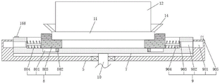
Referring to fig. 1-9, the invention provides an automatic coating and rotating mechanism for round cakes, which comprises a device box 1 and a motor 2 located at the middle position of the top of the device box 1, wherein the output end of the motor 2 arranged at the inner top of the device box 1 is connected with a rotating shaft 3 penetrating into the device box 1, the motor 2 and the rotating shaft 3 are assembled through a gear box, a fixing plate 4 and a driving component 13 for quantitatively controlling cream are assembled outside the rotating shaft 3, a lifting block 5 is slidably connected on the fixing plate 4, a rotating block 7 is arranged inside the lifting block 5, a clamping component 8 for clamping cakes and an adjusting component 9 for adjusting the driving component 13 are arranged on the rotating block 7, a blanking component 15 for blanking cream is arranged at the inner top of the device box 1, an adjusting component 16 for adjusting the lifting distance of the lifting block 5 is arranged on the side wall of the device box 1, the top of the fixed plate 4 is provided with an applying component 19 for applying cream, and the bottom of the fixed plate 4 is provided with a control component 22 through a mounting rack;
the inner bottom end of the device box 1 is provided with an annular plate 17, the inner side wall of the annular plate 17 is provided with annular teeth 18, the bottom of the rotating block 7 is provided with a rotating rod 10 penetrating through the bottom of the lifting block 5, the bottom of the rotating rod 10 is connected with a long column gear 21 meshed with the annular teeth 18, and the length of the long column gear 21 is long, so that when the lifting block 5 ascends and descends, the long column gear 21 can still be meshed with the annular teeth 18, and the work is not influenced.
Please refer to fig. 1, an electric telescopic rod 6 is disposed at the bottom of the fixing plate 4, an output end of the electric telescopic rod 6 is connected to a supporting plate, a top of the supporting plate is connected to the bottom of the lifting block 5 through a connecting block, the electric telescopic rod 6 is started, and the supporting plate and the lifting block 5 can be driven by the electric telescopic rod 6 to ascend and descend.
Please refer to fig. 4 and 5, the driving assembly 13 includes a mounting block 131 disposed on the rotating shaft 3, a groove 132 is disposed at an end of the mounting block 131 opposite to the rotating shaft 3, a second piston 133 is disposed inside the groove 132, a second connecting rod 134 extending to an outside of the mounting block 131 is disposed at a side of the second piston 133 opposite to the rotating shaft 3, and an arc-shaped block 135 is connected to a tail end of the second connecting rod 134.
Please refer to fig. 2, the top of the rotating block 7 is formed with a concave groove, the clamping assembly 8 includes a first sliding groove 801 formed at the bottom end of the concave groove and a first sliding block 802 slidably connected to the first sliding groove 801, a clamping block 803 is disposed at the top of the first sliding block 802, a spring 804 is disposed on a side of the clamping block 803 facing to a side wall of the concave groove, and the end of the spring 804 is fixedly connected with the side wall of the concave groove, the adjusting component 9 comprises a slot 902 arranged on the rotating block 7 and an annular groove 901 arranged on the lifting block 5, the annular groove 901 is communicated with the slot 902, a first piston 903 is arranged in the slot 902, and a first connecting rod 904 is connected to a side of the first piston 903 facing the spring 804, and a distal end of the first connecting rod 904 is connected to an outer wall of the clamping block 803, the adjusting assembly 9 further includes a first connecting pipe 905 communicating with the annular groove 901, and a distal end of the first connecting pipe 905 communicates with an inside of the groove 132.
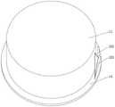
Please refer to fig. 1 and 2, the placing table 11 is clamped between two clamping blocks 803 of the clamping assembly 8, a pocket plate 14 is disposed at an outer edge of the top of the placing table 11, the pocket plate 14 is a circular ring structure, so as to prevent the cream from leaking out, and a cake main body 12 is disposed on the top of the placing table 11 and in the pocket plate 14.
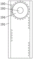
Please refer to fig. 1 and 3, the smearing component 19 includes a connecting block 192 sleeved on the rotating shaft 3 and a support rod 191 fixed on one side of the lifting block 5, the connecting block 192 is rotatably connected with a rotating column 193 through a bearing, a pinion 194 is sleeved on the rotating column 193, the end of the rotating column 193 is connected with a connecting piece 196, a cavity 197 and a second sliding groove 198 are formed in the connecting piece 196, a fifth piston 200 is arranged in the cavity 197, a second sliding block 202 is slidably connected in the second sliding groove 198, a second scraping plate 203 is connected to the bottom of the second sliding block 202, the second sliding block 202 is connected with the fifth piston 200 through a fixing rod 201, a first scraping plate 199 is arranged on one side of the second sliding groove 198 on the connecting piece 196, a tooth 195 meshed with the pinion 194 is arranged in the support rod 191, a triangular opening is formed in the second scraping plate 203, the triangular opening includes a vertical surface and a bending surface, the upright surface is used for smearing the cream on the cake uniformly, wherein the redundant cake can enter the inside of the second scraping plate 203 from the triangular opening and is stored by the bent surface, because the bent part on the bent surface is positioned at the high position of the cake, the space at the position of the second scraping plate 203 is larger, the cream can be stored in the space, and further the redundant cream can be positioned at the higher position, if the cream on the cake at the higher position is not uniformly smeared, the cream in the space can timely fill the non-uniform position, after the cream on the cake at the high position is uniformly smeared, the cream in the space can slide downwards due to gravity, so that the cream at the lower position can also be timely filled, in conclusion, the cream on the cake can be timely filled, and the waste caused by the cream falling onto the placing table 11 is avoided.
Please refer to fig. 2 and 6, the adjusting assembly 16 includes a connecting box 161 fixed above the fixing plate 4, a fourth piston 162 is disposed inside the connecting box 161, a fourth connecting rod 163 penetrating through the top of the connecting box 161 is rotatably connected to the top of the fourth piston 162 through a bearing, a handle 164 is disposed on the top of the fourth connecting rod 163, a connection portion between the fourth connecting rod 163 and the connecting box 161 is connected through a screw thread, a connection post 165 penetrating through the bottom of the connecting box 161 is disposed on the bottom of the fourth piston 162, a stopper 166 is disposed on the bottom of the connection post 165, a pressure switch 167 is disposed on the bottom of the stopper 166, and the adjusting assembly 16 further includes a touch block 168 disposed on the lifting block 5 and matched with the pressure switch 167.
Please refer to fig. 1, the discharging assembly 15 includes a fixed box 151 disposed at the top end of the device box 1, a feeding pipe 152 penetrating to the outside of the device box 1 is disposed at the top of the fixed box 151, a discharging pipe 153 is disposed at the bottom of the fixed box 151, check valves with opposite opening directions are disposed inside the feeding pipe 152 and the discharging pipe 153, respectively, a third piston 154 is disposed inside the fixed box 151, a third connecting rod 155 extending to the outside of the fixed box 151 is disposed on one side of the third piston 154 facing the rotating shaft 3, and a connecting ball 156 is connected to the end of the third connecting rod 155.
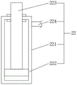
Referring to fig. 9, the control assembly 22 includes a control box 221 fixed at the bottom of the fixing plate 4 by a mounting bracket, a control piston 222 is disposed inside the control box 221, a control rod 223 penetrating to the top of the control box 221 and connected to the bottom of the lifting block 5 is disposed at the top of the control piston 222, a second connection pipe 224 is disposed at one side of the control box 221, and the end of the second connection pipe 224 is communicated with the cavity 197.
The working principle is as follows: when the cake placing device is used, the placing table 11 with the cake main body 12 is placed between the clamping blocks 803, the placing table 11 can be clamped under the action of the spring 804 through the arranged clamping blocks 803, meanwhile, the clamping blocks 803 can slide under the action of the first sliding grooves 801 and the first sliding blocks 802, so that the clamping blocks 803 can clamp the placing tables 11 with different sizes, cakes with different sizes are placed, meanwhile, the grooves 902, the annular grooves 901, the first connecting pipes 905 and the grooves 132 are internally linked with oil, when the placing table 11 with a larger size is clamped by the clamping blocks 803, the movement of the clamping blocks 803 can enable the first connecting rods 904 to drive the first pistons 903 to move, so that the oil in the grooves 902 can be compressed into the grooves 132, and further the second pistons 133 move back to the rotating shaft 3, so that the second connecting rods 134 gradually extend out of the mounting blocks 131, and in conclusion, when the placing table 11 is larger in size, the longer the second connecting rod 134 extends out of the mounting block 131, therefore, when the rotating shaft 3 drives the second connecting rod 134 and the arc-shaped block 135 to rotate, the longer the second connecting rod 134 extends out of the mounting block 131, the longer the distance of the connecting ball 156 compressed by the arc-shaped block 135, and further the longer the distance of the third piston 154, that is, the more the amount of milk compressed by the third piston is, in sum, when the size of the placing table 11 is increased, the more the amount of milk extruded by the blanking assembly 15 is, so as to meet the change of the amount of milk for cakes of various sizes, one device can be used for smearing cake cream of various sizes, and the use effect is better; after the cake main body 12 is placed between the clamping blocks 803, the electric telescopic rod 6 can be opened, the lifting block 5 can be driven to ascend and descend by the arranged electric telescopic rod 6, and cream is more and more evenly scraped, so that when the lifting block 5 ascends, the first scraping plate 199 can be ensured to be always in contact with and evenly scrape cream surfaces on the top of the cake main body 12, meanwhile, when the lifting block 5 ascends, the control rod 223 can drive the control piston 222 to move upwards, so that oil in the control box 221 can be pressed into the cavity 197, the second scraping plate 203 can be always in contact with and evenly scrape cream surfaces on the side edge of the cake main body 12, in addition, when the lifting block 5 ascends, the supporting rods 191 can be driven to ascend, because teeth 195 in the supporting rods 191 are distributed in a front-back staggered mode, when the supporting rods 191 ascend, the pinion 194 rotates forwards and backwards again under the action of the teeth 195, so that the first scraper 199 and the second scraper 203 can rub and scrape cream in a left-right swinging mode, the cream is more easily and uniformly smeared, and the smearing effect is better; in addition, because the pocket plate 14 is in a horn-shaped structure, cream can not fall into the placing platform 11 but be stored in the pocket plate 14, meanwhile, the second scraping plate 203 is provided with a triangular opening, the triangular opening comprises a vertical surface and a bending surface, the vertical surface is used for evenly smearing cream on the cake, redundant cake in the pocket plate 14 can enter the second scraping plate 203 from the triangular opening and is stored by the bending surface, because the bending part on the bending surface is positioned at the high position of the cake, the space positioned at the position inside the second scraping plate 203 is larger, cream can be stored in the space, and further redundant cream can be positioned at a higher position, if cream on the cake at the higher position is unevenly smeared, the cream in the space can timely fill the uneven position, and after the cream on the cake at the higher position is evenly smeared, cream is not replenished, therefore, the cream in the space can slide downwards due to gravity, so that the cream at the low position can be filled in time, therefore, the cream on the cake can be filled in time, and the cream is prevented from falling onto the placing table 11 to cause waste.
Although the present invention has been described in detail with reference to the foregoing embodiments, it will be apparent to those skilled in the art that various changes in the embodiments and/or modifications of the invention can be made, and equivalents and modifications of some features of the invention can be made without departing from the spirit and scope of the invention.
Claims (9)
1. The utility model provides a rotary mechanism is paintd automatically to circular cake, includes device case (1) and is located motor (2) of device case (1) top intermediate position, its characterized in that, the interior top of device case (1) is provided with the output of motor (2) is connected with and runs through pivot (3) to device case (1) inside, the outside of pivot (3) is equipped with fixed plate (4) and is used for carrying out quantitative control's drive assembly (13) to cream, and sliding connection has elevator (5) on fixed plate (4), and the inside of elevator (5) is provided with swivel block (7), be provided with on swivel block (7) and be used for carrying out the centre gripping subassembly (8) of centre gripping and be used for adjusting adjustment drive assembly (13) adjustment subassembly (9) to the cake, the interior top of device case (1) is provided with unloading subassembly (15) that are used for carrying out the unloading to cream, an adjusting component (16) used for adjusting the ascending distance of the lifting block (5) is arranged on the side wall of the device box (1), an smearing component (19) used for smearing cream is arranged at the top of the fixed plate (4), and a control component (22) is mounted at the bottom of the fixed plate (4) through a mounting frame;
the device is characterized in that an annular plate (17) is arranged at the inner bottom end of the device box (1), annular teeth (18) are arranged on the inner side wall of the annular plate (17), a rotating rod (10) penetrating to the bottom of the lifting block (5) is arranged at the bottom of the rotating block (7), and a long column gear (21) meshed with the annular teeth (18) is connected to the bottom of the rotating rod (10).
2. An automatic coating and rotating mechanism for round cakes according to claim 1, which is characterized in that: the bottom of the fixed plate (4) is provided with an electric telescopic rod (6), the output end of the electric telescopic rod (6) is connected with a supporting plate, and the top of the supporting plate is connected with the bottom of the lifting block (5) through a connecting block.
3. An automatic coating and rotating mechanism for round cakes according to claim 1, which is characterized in that: drive assembly (13) is including setting up installation piece (131) in pivot (3), installation piece (131) and the end of backing on the back of the body of pivot (3) are seted up fluted (132), and the inside of recess (132) is provided with second piston (133), one side that second piston (133) dorsad pivot (3) is provided with second connecting rod (134) that extend to installation piece (131) outside, and the end-to-end connection of second connecting rod (134) has arc piece (135).
4. An automatic coating and rotating mechanism for round cakes according to claim 3, which comprises: the top of the rotating block (7) is provided with a recessed groove, the clamping assembly (8) comprises a first sliding groove (801) arranged at the bottom end in the recessed groove and a first sliding block (802) in sliding connection with the first sliding groove (801), the top of the first sliding block (802) is provided with a clamping block (803), one surface, facing the side wall of the recessed groove, of the clamping block (803) is provided with a spring (804), the tail end of the spring (804) is fixedly connected with the side wall of the recessed groove, the adjusting assembly (9) comprises a slot (902) arranged on the rotating block (7) and an annular groove (901) arranged on the lifting block (5), the annular groove (901) is communicated with the slot (902), a first piston (903) is arranged inside the slot (902), one side, facing the spring (804), of the first piston (903) is connected with a first connecting rod (904), and the tail end of the first connecting rod (904) is connected with the outer wall of the clamping block (803), the adjustment assembly (9) further comprises a first connection pipe (905) communicating with the annular groove (901), and an end of the first connection pipe (905) communicates with the inside of the groove (132).
5. An automatic coating and rotating mechanism for round cakes according to claim 4, which comprises: two clamping blocks (803) in the clamping assembly (8) are clamped with a placing table (11), a pocket plate (14) is arranged at the outer edge of the top of the placing table (11), and a cake main body (12) is arranged at the top of the placing table (11) and in the pocket plate (14).
6. An automatic coating and rotating mechanism for round cakes according to claim 1, which is characterized in that: the smearing component (19) comprises a connecting block (192) sleeved on the rotating shaft (3) and a supporting rod (191) fixed on one side of the lifting block (5), the connecting block (192) is rotatably connected with a rotating column (193) through a bearing, a pinion (194) is sleeved on the rotating column (193), the tail end of the rotating column (193) is connected with a connecting piece (196), a cavity (197) and a second sliding groove (198) are formed in the connecting piece (196), a fifth piston (200) is arranged in the cavity (197), a second sliding block (202) is slidably connected in the second sliding groove (198), a second scraping plate (203) is connected to the bottom of the second sliding block (202), the second sliding block (202) is connected with the fifth piston (200) through a fixing rod (201), and a first scraping plate (199) is arranged on one side, located on the second sliding groove (198), of the connecting piece (196), teeth (195) meshed with the pinion (194) are arranged inside the support rod (191), and a triangular opening is formed in the second scraper (203).
7. An automatic coating and rotating mechanism for round cakes according to claim 1, which is characterized in that: the adjusting component (16) comprises a connecting box (161) fixed above the fixed plate (4), a fourth piston (162) is arranged in the connecting box (161), the top of the fourth piston (162) is rotatably connected with a fourth connecting rod (163) penetrating to the top of the connecting box (161) through a bearing, the top of the fourth connecting rod (163) is provided with a handle (164), and the connection part of the fourth connecting rod (163) and the connecting box (161) is connected through screw threads, the bottom of the fourth piston (162) is provided with a connecting column (165) which penetrates to the bottom of the connecting box (161), a stop block (166) is arranged at the bottom of the connecting column (165), a pressure switch (167) is arranged at the bottom of the stop block (166), the adjusting assembly (16) further comprises a touch block (168) which is arranged on the lifting block (5) and is matched with the pressure switch (167).
8. An automatic coating and rotating mechanism for round cakes according to claim 1, which is characterized in that: unloading subassembly (15) is including setting up fixed case (151) on top in device case (1), and the top of fixed case (151) is provided with and runs through to device case (1) outside inlet pipe (152), the bottom of fixed case (151) is provided with discharging pipe (153), the inside of fixed case (151) is provided with third piston (154), third piston (154) are provided with third connecting rod (155) that extend to fixed case (151) outside towards one side of pivot (3), and the end-to-end connection of third connecting rod (155) has connection ball (156).
9. An automatic coating and rotating mechanism for round cakes according to claim 1, which is characterized in that: control assembly (22) include fixes control box (221) in fixed plate (4) bottom through the mounting bracket, and the inside of control box (221) is provided with control piston (222), the top of control piston (222) is provided with and runs through to control box (221) top and with lifter (5) bottom control lever (223) be connected, one side of control box (221) is provided with second connecting pipe (224), and the end and cavity (197) intercommunication of second connecting pipe (224).
Priority Applications (1)
| Application Number | Priority Date | Filing Date | Title |
|---|---|---|---|
| CN202111360086.5A CN113973865B (en) | 2021-11-17 | 2021-11-17 | Automatic rotary mechanism of paining of circular cake |
Applications Claiming Priority (1)
| Application Number | Priority Date | Filing Date | Title |
|---|---|---|---|
| CN202111360086.5A CN113973865B (en) | 2021-11-17 | 2021-11-17 | Automatic rotary mechanism of paining of circular cake |
Publications (2)
| Publication Number | Publication Date |
|---|---|
| CN113973865A true CN113973865A (en) | 2022-01-28 |
| CN113973865B CN113973865B (en) | 2022-10-28 |
Family
ID=79748938
Family Applications (1)
| Application Number | Title | Priority Date | Filing Date |
|---|---|---|---|
| CN202111360086.5A Active CN113973865B (en) | 2021-11-17 | 2021-11-17 | Automatic rotary mechanism of paining of circular cake |
Country Status (1)
| Country | Link |
|---|---|
| CN (1) | CN113973865B (en) |
Cited By (2)
| Publication number | Priority date | Publication date | Assignee | Title |
|---|---|---|---|---|
| CN114504008A (en) * | 2022-03-07 | 2022-05-17 | 重庆真不赖食品有限公司 | Double-end blanking machine for cake production line |
| CN114651845A (en) * | 2022-03-16 | 2022-06-24 | 重庆真不赖食品有限公司 | Cream cake-based smearing equipment |
Citations (9)
| Publication number | Priority date | Publication date | Assignee | Title |
|---|---|---|---|---|
| DE3041197A1 (en) * | 1980-11-03 | 1982-06-03 | Karl 8551 Gößweinstein Rinderle | Multilayer pastry making machine - with dispenser, spreader bell and revolving spreader bracket |
| CN205902725U (en) * | 2016-06-19 | 2017-01-25 | 牛歆蔚 | Cream automatic spraying device |
| CN106417439A (en) * | 2016-12-08 | 2017-02-22 | 中山职业技术学院 | Automatic cake cream smearing equipment |
| CN106614878A (en) * | 2016-11-15 | 2017-05-10 | 华北电力大学(保定) | 3D printer for cream cake |
| CN106922772A (en) * | 2017-04-25 | 2017-07-07 | 苏州市淞舜五金有限公司 | One kind automatically smears butter machine |
| CN209390961U (en) * | 2018-08-20 | 2019-09-17 | 广东森乐食品有限公司 | A kind of rotatable bracket of cake making |
| CN111742952A (en) * | 2020-08-04 | 2020-10-09 | 呼和浩特蒙特利莱机械有限公司 | Assembly line is with device is paintd to adjustable single cream who paints thickness |
| CN113491278A (en) * | 2021-07-21 | 2021-10-12 | 赣州市倞华菲尔雪食品有限公司 | Automatic rotary equipment of paining of circular cake |
| CN113615720A (en) * | 2021-07-30 | 2021-11-09 | 海南薇薇安食品有限公司 | Cream smearing support frame for cake production |
-
2021
- 2021-11-17 CN CN202111360086.5A patent/CN113973865B/en active Active
Patent Citations (9)
| Publication number | Priority date | Publication date | Assignee | Title |
|---|---|---|---|---|
| DE3041197A1 (en) * | 1980-11-03 | 1982-06-03 | Karl 8551 Gößweinstein Rinderle | Multilayer pastry making machine - with dispenser, spreader bell and revolving spreader bracket |
| CN205902725U (en) * | 2016-06-19 | 2017-01-25 | 牛歆蔚 | Cream automatic spraying device |
| CN106614878A (en) * | 2016-11-15 | 2017-05-10 | 华北电力大学(保定) | 3D printer for cream cake |
| CN106417439A (en) * | 2016-12-08 | 2017-02-22 | 中山职业技术学院 | Automatic cake cream smearing equipment |
| CN106922772A (en) * | 2017-04-25 | 2017-07-07 | 苏州市淞舜五金有限公司 | One kind automatically smears butter machine |
| CN209390961U (en) * | 2018-08-20 | 2019-09-17 | 广东森乐食品有限公司 | A kind of rotatable bracket of cake making |
| CN111742952A (en) * | 2020-08-04 | 2020-10-09 | 呼和浩特蒙特利莱机械有限公司 | Assembly line is with device is paintd to adjustable single cream who paints thickness |
| CN113491278A (en) * | 2021-07-21 | 2021-10-12 | 赣州市倞华菲尔雪食品有限公司 | Automatic rotary equipment of paining of circular cake |
| CN113615720A (en) * | 2021-07-30 | 2021-11-09 | 海南薇薇安食品有限公司 | Cream smearing support frame for cake production |
Cited By (3)
| Publication number | Priority date | Publication date | Assignee | Title |
|---|---|---|---|---|
| CN114504008A (en) * | 2022-03-07 | 2022-05-17 | 重庆真不赖食品有限公司 | Double-end blanking machine for cake production line |
| CN114504008B (en) * | 2022-03-07 | 2022-08-19 | 重庆真不赖食品有限公司 | Double-end blanking machine for cake production line |
| CN114651845A (en) * | 2022-03-16 | 2022-06-24 | 重庆真不赖食品有限公司 | Cream cake-based smearing equipment |
Also Published As
| Publication number | Publication date |
|---|---|
| CN113973865B (en) | 2022-10-28 |
Similar Documents
| Publication | Publication Date | Title |
|---|---|---|
| CN113973865B (en) | Automatic rotary mechanism of paining of circular cake | |
| CN110978169B (en) | Automatic patching device of wooden furniture | |
| CN110497489B (en) | Wood board glue smearing machine | |
| CN114563346A (en) | Cement bonding strength detection device | |
| CN201105255Y (en) | Oiling machine | |
| CN111701810B (en) | Chemical agent conveying pipeline rust-proof treatment device | |
| CN110961310B (en) | Steel wire rope oiling and maintaining device | |
| CN210675777U (en) | Novel automatic gluing device | |
| CN112756200A (en) | Dispensing equipment with anti-blocking function | |
| CN210279657U (en) | Environment-friendly aluminum honeycomb core's rubber coating device | |
| CN111686983A (en) | Device capable of uniformly spraying inner wall and bottom wall of vacuum cup | |
| CN114534854B (en) | Grinding device for beef paste preparation | |
| CN115532515A (en) | Compatible formula rubberizing equipment | |
| CN213388391U (en) | Reagent adding device for glass cleaning | |
| CN111706046A (en) | Automatic putty scraping device on wall surface with height capable of being manually adjusted | |
| CN220697268U (en) | Edge sealing and glue spraying device for panel furniture | |
| CN215141569U (en) | Connecting conduit adhesive deposite device | |
| CN215354166U (en) | Coating equipment capable of adjusting object position | |
| CN220371467U (en) | Novel dispensing mechanism for dispensing machine | |
| CN212524769U (en) | Paste instant-dry glue dispensing device | |
| CN219232910U (en) | Automatic dispensing device | |
| CN217699953U (en) | Automatic scaling powder coating device | |
| CN215050696U (en) | Boiler outer wall cladding spraying equipment | |
| CN219683154U (en) | Glue spreading device for automobile parts | |
| CN218985950U (en) | Corrugated board indentation device |
Legal Events
| Date | Code | Title | Description |
|---|---|---|---|
| PB01 | Publication | ||
| PB01 | Publication | ||
| SE01 | Entry into force of request for substantive examination | ||
| SE01 | Entry into force of request for substantive examination | ||
| GR01 | Patent grant | ||
| GR01 | Patent grant |