CN113957833A - Environment-friendly wet-type leaf water-soil separation garbage truck - Google Patents
Environment-friendly wet-type leaf water-soil separation garbage truck Download PDFInfo
- Publication number
- CN113957833A CN113957833A CN202111344111.0A CN202111344111A CN113957833A CN 113957833 A CN113957833 A CN 113957833A CN 202111344111 A CN202111344111 A CN 202111344111A CN 113957833 A CN113957833 A CN 113957833A
- Authority
- CN
- China
- Prior art keywords
- water
- backup pad
- supporting plate
- garbage truck
- push rod
- Prior art date
- Legal status (The legal status is an assumption and is not a legal conclusion. Google has not performed a legal analysis and makes no representation as to the accuracy of the status listed.)
- Pending
Links
- 239000002689 soil Substances 0.000 title claims abstract description 19
- 238000000926 separation method Methods 0.000 title claims abstract description 11
- XLYOFNOQVPJJNP-UHFFFAOYSA-N water Substances O XLYOFNOQVPJJNP-UHFFFAOYSA-N 0.000 claims abstract description 116
- 239000002699 waste material Substances 0.000 claims abstract description 21
- 239000000463 material Substances 0.000 claims abstract description 8
- 230000007246 mechanism Effects 0.000 claims description 54
- 238000004140 cleaning Methods 0.000 claims description 9
- 238000001035 drying Methods 0.000 claims description 9
- 239000007788 liquid Substances 0.000 claims description 7
- XBWAZCLHZCFCGK-UHFFFAOYSA-N 7-chloro-1-methyl-5-phenyl-3,4-dihydro-2h-1,4-benzodiazepin-1-ium;chloride Chemical compound [Cl-].C12=CC(Cl)=CC=C2[NH+](C)CCN=C1C1=CC=CC=C1 XBWAZCLHZCFCGK-UHFFFAOYSA-N 0.000 claims description 4
- 230000002093 peripheral effect Effects 0.000 claims description 3
- 230000009467 reduction Effects 0.000 claims description 2
- 230000007613 environmental effect Effects 0.000 abstract description 4
- ZDXLFJGIPWQALB-UHFFFAOYSA-M disodium;oxido(oxo)borane;chlorate Chemical compound [Na+].[Na+].[O-]B=O.[O-]Cl(=O)=O ZDXLFJGIPWQALB-UHFFFAOYSA-M 0.000 abstract 1
- 238000010586 diagram Methods 0.000 description 5
- 235000013547 stew Nutrition 0.000 description 3
- 230000009471 action Effects 0.000 description 2
- 230000008878 coupling Effects 0.000 description 2
- 238000010168 coupling process Methods 0.000 description 2
- 238000005859 coupling reaction Methods 0.000 description 2
- 239000002351 wastewater Substances 0.000 description 2
- 241000196324 Embryophyta Species 0.000 description 1
- 244000007853 Sarothamnus scoparius Species 0.000 description 1
- 206010044565 Tremor Diseases 0.000 description 1
- 230000002337 anti-port Effects 0.000 description 1
- 230000007547 defect Effects 0.000 description 1
- 230000003203 everyday effect Effects 0.000 description 1
- 238000000605 extraction Methods 0.000 description 1
- 238000002347 injection Methods 0.000 description 1
- 239000007924 injection Substances 0.000 description 1
- 230000004048 modification Effects 0.000 description 1
- 238000012986 modification Methods 0.000 description 1
- 230000003287 optical effect Effects 0.000 description 1
- 238000005086 pumping Methods 0.000 description 1
- 239000000243 solution Substances 0.000 description 1
- 238000009834 vaporization Methods 0.000 description 1
- 230000008016 vaporization Effects 0.000 description 1
Images


Classifications
-
- E—FIXED CONSTRUCTIONS
- E01—CONSTRUCTION OF ROADS, RAILWAYS, OR BRIDGES
- E01H—STREET CLEANING; CLEANING OF PERMANENT WAYS; CLEANING BEACHES; DISPERSING OR PREVENTING FOG IN GENERAL CLEANING STREET OR RAILWAY FURNITURE OR TUNNEL WALLS
- E01H1/00—Removing undesirable matter from roads or like surfaces, with or without moistening of the surface
- E01H1/08—Pneumatically dislodging or taking-up undesirable matter or small objects; Drying by heat only or by streams of gas; Cleaning by projecting abrasive particles
- E01H1/0827—Dislodging by suction; Mechanical dislodging-cleaning apparatus with independent or dependent exhaust, e.g. dislodging-sweeping machines with independent suction nozzles ; Mechanical loosening devices working under vacuum
- E01H1/0836—Apparatus dislodging all of the dirt by suction ; Suction nozzles
-
- F—MECHANICAL ENGINEERING; LIGHTING; HEATING; WEAPONS; BLASTING
- F26—DRYING
- F26B—DRYING SOLID MATERIALS OR OBJECTS BY REMOVING LIQUID THEREFROM
- F26B21/00—Arrangements or duct systems, e.g. in combination with pallet boxes, for supplying and controlling air or gases for drying solid materials or objects
- F26B21/001—Drying-air generating units, e.g. movable, independent of drying enclosure
-
- F—MECHANICAL ENGINEERING; LIGHTING; HEATING; WEAPONS; BLASTING
- F26—DRYING
- F26B—DRYING SOLID MATERIALS OR OBJECTS BY REMOVING LIQUID THEREFROM
- F26B21/00—Arrangements or duct systems, e.g. in combination with pallet boxes, for supplying and controlling air or gases for drying solid materials or objects
- F26B21/004—Nozzle assemblies; Air knives; Air distributors; Blow boxes
-
- G—PHYSICS
- G05—CONTROLLING; REGULATING
- G05B—CONTROL OR REGULATING SYSTEMS IN GENERAL; FUNCTIONAL ELEMENTS OF SUCH SYSTEMS; MONITORING OR TESTING ARRANGEMENTS FOR SUCH SYSTEMS OR ELEMENTS
- G05B19/00—Programme-control systems
- G05B19/02—Programme-control systems electric
- G05B19/04—Programme control other than numerical control, i.e. in sequence controllers or logic controllers
- G05B19/042—Programme control other than numerical control, i.e. in sequence controllers or logic controllers using digital processors
- G05B19/0423—Input/output
Landscapes
- Engineering & Computer Science (AREA)
- Mechanical Engineering (AREA)
- General Engineering & Computer Science (AREA)
- Physics & Mathematics (AREA)
- General Physics & Mathematics (AREA)
- Automation & Control Theory (AREA)
- Architecture (AREA)
- Civil Engineering (AREA)
- Structural Engineering (AREA)
- Processing Of Solid Wastes (AREA)
Abstract
The invention relates to a garbage truck, in particular to a wet-type leaf water-soil separation garbage truck for environmental protection. The invention aims to provide an environment-friendly wet type leaf water-soil separation garbage truck which can automatically collect leaves and can filter moisture on the leaves so that the leaves cannot rot quickly. The utility model provides a wet-type leaf water and soil separation garbage truck for environmental protection, is equipped with the second backup pad including wheel, first backup pad and second backup pad in first backup pad bottom one side, and one side that first backup pad was kept away from at second backup pad top is equipped with the third backup pad, and first backup pad and the equal symmetric rotation formula in third backup pad bottom are equipped with the wheel. The user presses contact switch, and control module control air pump is opened, and the air pump is bled to inhale the material pipe and adsorb the leaf, make the leaf drop in the waste material through hose and feeding frame, the sanitationman constantly promote this equipment remove can, so need not that the sanitationman is manual to clean the leaf.
Description
Technical Field
The invention relates to a garbage truck, in particular to a wet-type leaf water-soil separation garbage truck for environmental protection.
Background
In modern city, each position greening engineering is comparatively perfect, and the equal interval in road both sides evenly plants green tree, and green tree can drop some leaves at ordinary times, and when the autumn, a large amount of leaves can drop, can keep clean and tidy and pleasing to the eye for the street, and the sanitationman needs clean the fallen leaves.
Sanitationman generally cleans the leaf through handheld broom, and clean the leaf to piling up together, then unify the collection to the leaf through the garbage truck, because all can the watering on the road surface every day, perhaps meet rainy weather, can be stained with water on the leaf, thereby the leaf that is stained with water in a large number piles up the easy rotten, send comparatively sharp smell in making the garbage truck, and artifical manual cleaning the leaf, make sanitationman's work load great.
Therefore, it is necessary to design a wet-type leaf water and soil separating garbage truck for environmental protection, which can automatically collect leaves and filter the moisture on the leaves to prevent the leaves from being rotted quickly.
Disclosure of Invention
The invention aims to overcome the defects that a large amount of wet leaves are easy to accumulate and rot, so that the garbage truck can emit pungent smell, and the sanitation workers have large workload by manually cleaning the leaves.
The technical scheme is as follows: an environment-friendly wet-type leaf water-soil separation garbage truck comprises wheels, a first supporting plate, a second supporting plate, connecting rods, a third supporting plate, a second push rod, a contact switch, a waste bin, a suction pipe, a hose, an air pump, a feeding frame, first fixing columns, torsional springs, supporting rods, a fixing mechanism and a standing mechanism, wherein the second supporting plate is arranged on one side of the bottom of the first supporting plate, the third supporting plate is arranged on one side, away from the first supporting plate, of the top of the second supporting plate, the wheels are symmetrically and rotatably arranged at the bottoms of the first supporting plate and the third supporting plate, the connecting rods are symmetrically arranged between the tops of the first supporting plate and the third supporting plate in a front-back manner, the second push rod is arranged on one side, away from the first supporting plate, of the top of the third supporting plate, the contact switch is arranged on one side, close to the second push rod, of the top of the first supporting plate, the first fixing columns are arranged on one side in the middle of the top of the first supporting plate, the opposite side is equipped with the die-pin in the middle of the first backup pad top, and the last rotation type of first fixed column is equipped with the feeding frame, is connected with the torsional spring between feeding frame and the first fixed column, and feeding frame top is connected with the air pump, is equipped with the hose on the air pump, is equipped with on the hose and inhales the material pipe, and first backup pad top left side is equipped with fixed establishment, is connected with the mechanism of stewing in the third backup pad.
As a further preferred scheme, the fixing mechanism comprises a second fixing column, a first clamping plate, a first linear spring, a second clamping plate and a pull rod, wherein the second fixing column is symmetrically arranged on one side of the top of the first supporting plate away from the second push rod, the first clamping plate is arranged between the second fixing columns, the second clamping plate is arranged between the second fixing columns in a sliding mode and located on the upper side of the first clamping plate, the first linear spring is connected between the upper side of the second clamping plate and the second fixing column, and the pull rod is arranged at the top of the second clamping plate.
As a further preferred scheme, the standing mechanism comprises a first water delivery pipe, a standing box and a moving frame, the top of the third supporting plate is provided with the standing box in a fixed connection mode, the first water delivery pipe is connected between the standing box and the waste box, and the moving frame is arranged on the standing box in a sliding mode.
As further preferred scheme, still including the shake mechanism, the shake mechanism is including gear motor, the cam, first push rod, photoelectric sensor, first transparent plate, the filter, second linear spring and slide bar, first backup pad top one side is equipped with gear motor, be equipped with the cam on gear motor's the output shaft, waste bin upside position is equipped with first transparent plate and photoelectric sensor, the symmetry formula is equipped with the slide bar in the waste bin, slidingtype is equipped with the filter between the slide bar, all be connected with second linear spring between filter and the slide bar, be connected with first push rod between the filter top both sides.
As a further preferred scheme, the automatic cleaning device further comprises a cleaning mechanism, wherein the cleaning mechanism comprises a fixed frame, a water tank, a second water conveying pipe and a water pump, the fixed frame is arranged at the top of the second supporting plate, the water tank is placed on the fixed frame, the second water conveying pipe is arranged on the upper side of the water tank and connected with a waste box, and the water pump is arranged on the second water conveying pipe.
As a further preferred scheme, the water tank further comprises a warning mechanism, the warning mechanism comprises a water flow sensor, a third fixing column, an electric push rod and a first baffle, the water flow sensor is arranged on the second water conveying pipe, the third fixing column is arranged at the top of the water tank, the electric push rod is arranged on the third fixing column, and the first baffle is arranged on a telescopic rod of the electric push rod.
As a further preferred scheme, still including drying mechanism, drying mechanism is including the second baffle, the third raceway, level sensor, the second transparent plate, fourth fixed column and air heater, the case top of stewing is equipped with the second baffle, the intercommunication has the third raceway between second baffle and the water tank top, the downside position of case one side of stewing is equipped with level sensor and second transparent plate, the case of stewing is last to keep away from one side of level sensor and is equipped with the fourth fixed column, be equipped with the air heater on the fourth fixed column.
As a further preferable scheme, the device further comprises a control box, the second push rod is provided with the control box, a storage battery, a control module and a power module are installed in the control box, the storage battery supplies power for the whole device, the output end of the storage battery is electrically connected with the power module, the power module is connected with a power main switch through a circuit, and the control module is electrically connected with the power module; the control module is connected with a DS1302 clock circuit and a 24C02 circuit; the liquid level sensor, the water flow sensor, the photoelectric sensor and the contact switch are electrically connected with the control module, and the electric push rod, the air heater, the air pump, the speed reducing motor and the water pump are connected with the control module through a peripheral circuit.
The invention has the following advantages: 1. a user presses the contact switch, the control module controls the air pump to be turned on, the air pump performs air extraction, and therefore the leaf is adsorbed by the material suction pipe, falls into waste materials through the hose and the feeding frame, and is continuously pushed to move by sanitation workers, so that the leaves do not need to be manually cleaned by the sanitation workers;
2. water pump second raceway is with the water pumping in the water tank to the dump bin, and water can simply wash the earth on the leaf, and gear motor's output shaft rotates simultaneously and drives the cam and rotate, and the cam makes filter intermittent type nature rebound for water on the leaf can tremble down fast, and water flows to removing in the frame through first raceway, so can get rid of the soil and water on the leaf.
Drawings
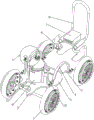
Fig. 1 is a schematic perspective view of the present invention.
FIG. 2 is a schematic view of a first partial body structure according to the present invention.
FIG. 3 is a schematic view of a second partial body structure according to the present invention.
Fig. 4 is an enlarged schematic perspective view of the invention at a.
Fig. 5 is a schematic perspective view of the fixing mechanism of the present invention.
FIG. 6 is an enlarged perspective view of the present invention at B.
Fig. 7 is a schematic structural view of a first partial body of the standing mechanism of the present invention.
Fig. 8 is a schematic structural view of a second partial body of the standing mechanism of the invention.
FIG. 9 is a schematic diagram of a first partial body structure of the dithering mechanism of the present invention.
FIG. 10 is a schematic diagram of a second partial body structure of the dithering mechanism of the present invention.
FIG. 11 is a perspective view of the cleaning mechanism of the present invention.
FIG. 12 is an enlarged perspective view of the present invention at C.
Fig. 13 is a schematic perspective view of a warning mechanism of the present invention.
Fig. 14 is a schematic structural diagram of a first partial body of the drying mechanism of the present invention.
Fig. 15 is a schematic structural view of a second partial body of the drying mechanism of the present invention.
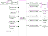
Fig. 16 is a circuit block diagram of the present invention.
Fig. 17 is a schematic circuit diagram of the present invention.
Number designation in the figures: 1-wheel, 2-first supporting plate, 3-second supporting plate, 4-connecting rod, 5-third supporting plate, 6-second push rod, 7-control box, 8-contact switch, 9-waste box, 10-suction pipe, 11-hose, 12-air pump, 13-feeding frame, 14-first fixed column, 15-torsion spring, 16-supporting rod, 17-fixing mechanism, 171-second fixed column, 172-first clamping plate, 173-first linear spring, 174-second clamping plate, 175-pull rod, 18-standing mechanism, 181-first water pipe, 182-standing box, 183-moving frame, 19-shaking mechanism, 191-speed reducing motor, 192-cam, 193-first push rod, 194-photoelectric sensor, 195-a first transparent plate, 196-a filter plate, 197-a second linear spring, 198-a slide bar, 20-a cleaning mechanism, 201-a fixed frame, 202-a water tank, 203-a second water pipe, 204-a water pump, 21-a warning mechanism, 211-a water flow sensor, 212-a third fixed column, 213-an electric push rod, 214-a first baffle, 22-a drying mechanism, 221-a second baffle, 222-a third water pipe, 223-a liquid level sensor, 224-a second transparent plate, 225-a fourth fixed column, 226-a hot air blower.
Detailed Description
The following further describes the technical solution with reference to specific embodiments, and it should be noted that: the words upper, lower, left, right, and the like used herein to indicate orientation are merely for the location of the illustrated structure in the corresponding figures. The serial numbers of the parts are themselves numbered herein, for example: first, second, etc. are used solely to distinguish one from another as to objects described herein, and do not have any sequential or technical meaning. The application states that: the connection and coupling, unless otherwise indicated, include both direct and indirect connections (couplings).
Example 1
An environment-friendly wet-type leaf water and soil separation garbage truck is shown in figures 1-8 and comprises wheels 1, a first supporting plate 2, a second supporting plate 3, a connecting rod 4, a third supporting plate 5, a second push rod 6, a contact switch 8, a waste bin 9, a material suction pipe 10, a hose 11, an air pump 12, a feeding frame 13, a first fixed column 14, a torsion spring 15, a supporting rod 16, a fixing mechanism 17 and a standing mechanism 18, wherein the second supporting plate 3 is arranged on the right side of the bottom of the first supporting plate 2, the third supporting plate 5 is arranged on the right side of the top of the second supporting plate 3, the wheels 1 are symmetrically and rotatably arranged at the bottoms of the first supporting plate 2 and the third supporting plate 5 in a front-back symmetrical mode, the connecting rods 4 are symmetrically arranged between the tops of the first supporting plate 2 and the third supporting plate 5 in a front-back mode, the second push rod 6 is arranged on the right side of the top of the third supporting plate 5, the contact switch 8 is arranged on the right side of the top of the third supporting plate 5, the top of the first supporting plate 2 is provided with the waste bin 9, rear side is equipped with first fixed column 14 in the middle of 2 tops of first backup pad, and the front side is equipped with die-pin 16 in the middle of 2 tops of first backup pad, and the last rotation type of first fixed column 14 is equipped with feeding frame 13, is connected with torsional spring 15 between feeding frame 13 and the first fixed column 14, and feeding frame 13 top is connected with air pump 12, is equipped with hose 11 on the air pump 12, and hose 11 left side is equipped with inhales material pipe 10, and 2 top left sides of first backup pad are equipped with fixed establishment 17, are connected with the mechanism 18 that stews on the third backup pad 5.
The fixing mechanism 17 comprises a second fixing column 171, a first clamping plate 172, a first linear spring 173, a second clamping plate 174 and a pull rod 175, the second fixing column 171 is symmetrically arranged on the left side of the top of the first supporting plate 2 in a front-back manner, the first clamping plate 172 is arranged between the second fixing columns 171, the second clamping plate 174 is arranged between the second fixing columns 171 in a sliding manner, the second clamping plate 174 is located on the upper side of the first clamping plate 172, the first linear spring 173 is connected between the upper side of the second clamping plate 174 and the second fixing column 171, and the pull rod 175 is arranged on the top of the second clamping plate 174.
The standing mechanism 18 comprises a first water pipe 181, a standing box 182 and a moving frame 183, the top of the third supporting plate 5 is provided with the standing box 182, the first water pipe 181 is connected between the standing box 182 and the waste box 9, and the moving frame 183 is arranged on the standing box 182 in a sliding manner.
The user can push the garbage truck to collect the leaves, the user moves the garbage truck to the position where the leaves need to be collected through the second push rod 6, then the wheel 1 rolls, then the power main switch is pressed, the garbage truck is powered on, the user moves the second clamping plate 174 upwards through the pull rod 175, the first linear spring 173 is compressed, then the user places the hose 11 and the suction pipe 10 at the position between the first clamping plate 172 and the second clamping plate 174, then no force is applied to the pull rod 175 any more, under the reset action of the second clamping plate 174, the second clamping plate 174 moves downwards, the hose 11 and the suction pipe 10 are fixed and limited, the user presses the contact switch 8, the contact switch 8 sends out a signal, the control module receives the signal, the air pump 12 is controlled to be turned on, the air pump 12 performs air suction, so that the suction pipe 10 adsorbs the leaves, the leaves fall into the waste bin 9 through the hose 11 and the feeding frame 13, if the leaf is wet, remaining water on the leaf flows to the removal frame 183 of the case 182 of stewing through first raceway 181, and the user can take out removal frame 183 to waste water in removing frame 183 clears up, inhales material pipe 10 and need not collect the leaf, and the user can press contact switch 8 once more, and contact switch 8 signals, control module received signal, and control air pump 12 closes, presses the power master switch again, with this garbage truck outage can.
Example 2
On the basis of the embodiment 1, as shown in figure 1, figure 2, figure 9, figure 10, figure 11, figure 12, figure 13 and figure 14, fig. 15, fig. 16 and fig. 17 show, still include shake mechanism 19, shake mechanism 19 including gear motor 191, cam 192, first push rod 193, photoelectric sensor 194, first transparent plate 195, filter plate 196, second linear spring 197 and slide bar 198, first support plate 2 top left side is equipped with gear motor 191, be equipped with cam 192 on the output shaft of gear motor 191, the upper left side of waste bin 9 is equipped with first transparent plate 195 and photoelectric sensor 194, photoelectric sensor 194 is located the left side of first transparent plate 195, the front and back symmetry formula is equipped with slide bar 198 in the waste bin 9, the slidingtype is equipped with filter plate 196 between the slide bar 198, all be connected with second linear spring 197 between filter plate 196 and the slide bar 198, be connected with first push rod 193 between the front and back both sides of filter plate 196 top.
Still including wiper mechanism 20, wiper mechanism 20 is equipped with fixed frame 201 including fixed frame 201, water tank 202, second raceway 203 and water pump 204 on the top of second backup pad 3, has placed water tank 202 on fixed frame 201, and the upper left side of water tank 202 is equipped with second raceway 203, and second raceway 203 left side is connected with waste bin 9, and second raceway 203 left side is equipped with water pump 204.
The user injects a certain amount of water into the water tank 202, the air pump 12 sucks air to continuously adsorb leaves through the suction pipe 10, the space between the leaves in the waste bin 9 is gradually increased to block the right side of the first transparent plate 195, when the photoelectric sensor 194 detects that the optical signal is lower than the rated value, the photoelectric sensor 194 sends a signal, the control module receives the signal to control the air pump 12 to be turned off, the control module controls the speed reducing motor 191 and the water pump 204 to be started for 10 seconds, the water pump 204 pumps the water in the water tank 202 to the waste bin 9 through the second water pipe 203, the water can simply wash soil on the leaves, meanwhile, the output shaft of the speed reducing motor 191 rotates to drive the cam 192 to rotate, the cam 192 is in contact fit with the first push rod 193 and intermittently pushes up the first push rod 193, so that the filter plate 196 intermittently moves upwards along the slide rod 198, and the second linear spring 197 is adaptively deformed, simultaneously the filter 196 drives the leaf and shakes, make the water on the leaf shake down fast, and flow out through first raceway 181, 10 seconds later, gear motor 191 and water pump 204 close, then the user rotates feeding frame 13, make torsional spring 15 take place deformation, the user can take out and collect the leaf that washs, thereby can carry out waste utilization to the leaf, then the user no longer exerts force to feeding frame 13, under torsional spring 15's reset action, feeding frame 13 antiport resets, die-pin 16 can hold feeding frame 13.
Still including warning mechanism 21, warning mechanism 21 is equipped with water flow sensor 211 including water flow sensor 211, third fixed column 212, electric putter 213 and first baffle 214 on the second raceway 203, and water tank 202 top front side is equipped with third fixed column 212, is equipped with electric putter 213 on the third fixed column 212, is equipped with first baffle 214 on electric putter 213's the telescopic link.
In an initial state, the water tank 202 does not contain water, the telescopic rod of the electric push rod 213 is in an extended state, so that the first baffle 214 does not block the upper side position of the top of the water tank 202, at this time, a user can fill the water tank 202 with water, when the water pump 204 pumps water through the second water pipe 203, the water flow sensor 211 detects that the water flow of the second water pipe 203 is higher than a rated value, the water flow sensor 211 sends a signal, the control module receives the signal and controls the electric push rod 213 to start, the telescopic rod of the electric push rod 213 is shortened by 1 second, so that the electric push rod 213 drives the first baffle 214 to move upwards, the first baffle 214 blocks the opening position of the top of the water tank 202, after 1 second, the electric push rod 213 is closed, when the water flow of the second water pipe 203 is detected by the water flow sensor 211 after the water in the water tank 202 is pumped out, the water flow sensor 211 sends a signal, control module received signal, control electric putter 213 starts, and electric putter 213's telescopic link extension 1 second, and electric putter 213's telescopic link drives first baffle 214 and moves down, and 1 second back, electric putter 213 closes, and the opening at water tank 202 top is no longer blockked up to first baffle 214 to can indicate the user to carry out the water injection to water tank 202.
Still including drying mechanism 22, drying mechanism 22 is including second baffle 221, third raceway 222, level sensor 223, second transparent plate 224, fourth fixed column 225 and air heater 226, it is equipped with second baffle 221 to stew the case 182 top, the intercommunication has third raceway 222 between second baffle 221 and the water tank 202 top, the downside is equipped with level sensor 223 and second transparent plate 224 before the case 182 of stewing, level sensor 223 is located second transparent plate 224 front side, the upside is equipped with fourth fixed column 225 behind the case 182 of stewing, be equipped with air heater 226 on the fourth fixed column 225.
Waste water lets in removing frame 183 in second raceway 203, when level sensor 223 sees through second transparent plate 224 and detects that the water level in removing frame 183 is higher than the rating, level sensor 223 signals, control module received signal, control air heater 226 starts, air heater 226 dries to the case 182 that stews, make the water vaporization into steam in removing frame 183, and circulate to liquefaction into water in the water tank 202 through third raceway 222, so can carry out reuse to water, when level sensor 223 sees through second transparent plate 224 and detects that the water level in removing frame 183 is less than the rating, level sensor 223 signals, control module received signal, control air heater 226 closes.
The device is characterized by further comprising a control box 7, the control box 7 is arranged on the second push rod 6, a storage battery, a control module and a power module are installed in the control box 7, the storage battery supplies power for the whole device, the output end of the storage battery is electrically connected with the power module, the power module is connected with a power main switch through a circuit, and the control module is electrically connected with the power module; the control module is connected with a DS1302 clock circuit and a 24C02 circuit; the liquid level sensor 223, the water flow sensor 211, the photoelectric sensor 194 and the contact switch 8 are electrically connected with the control module, and the electric push rod 213, the hot air blower 226, the air pump 12, the speed reduction motor 191 and the water pump 204 are connected with the control module through a peripheral circuit.
Finally, it should be noted that: although the present invention has been described in detail with reference to the foregoing embodiments, it will be apparent to those skilled in the art that modifications may be made to the embodiments or portions thereof without departing from the spirit and scope of the invention.
Claims (8)
1. An environment-friendly wet-type leaf water and soil separation garbage truck is characterized by comprising wheels (1), a first supporting plate (2), a second supporting plate (3), a connecting rod (4), a third supporting plate (5), a second push rod (6), a contact switch (8), a waste bin (9), a material suction pipe (10), a hose (11), an air pump (12), a feeding frame (13), a first fixed column (14), a torsion spring (15), a supporting rod (16), a fixing mechanism (17) and a standing mechanism (18), wherein the second supporting plate (3) is arranged on one side of the bottom of the first supporting plate (2), the third supporting plate (5) is arranged on one side of the top of the second supporting plate (3) far away from the first supporting plate (2), the wheels (1) are symmetrically arranged at the bottoms of the first supporting plate (2) and the third supporting plate (5), the connecting rod (4) is symmetrically arranged between the tops of the first supporting plate (2) and the third supporting plate (5) in a front-back manner, keep away from one side of first backup pad (2) on third backup pad (5) top and be equipped with second push rod (6), one side that third backup pad (5) top is close to second push rod (6) is equipped with contact switch (8), first backup pad (2) top is equipped with dump bin (9), one side is equipped with first fixed column (14) in the middle of first backup pad (2) top, the opposite side is equipped with die-pin (16) in the middle of first backup pad (2) top, the last rotation type of first fixed column (14) is equipped with feeding frame (13), be connected with torsional spring (15) between feeding frame (13) and first fixed column (14), feeding frame (13) top is connected with air pump (12), be equipped with hose (11) on air pump (12), be equipped with on hose (11) and inhale material pipe (10), first backup pad (2) top left side is equipped with fixed establishment (17), be connected with mechanism of standing (18) on third backup pad (5).
2. The environment-friendly wet type leaf water and soil separating garbage truck as claimed in claim 1, wherein the fixing mechanism (17) comprises second fixing columns (171), first clamping plates (172), first linear springs (173), second clamping plates (174) and pull rods (175), the second fixing columns (171) are symmetrically arranged on one sides of the tops of the first supporting plates (2) far away from the second push rods (6), the first clamping plates (172) are arranged between the second fixing columns (171), the second clamping plates (174) are slidably arranged between the second fixing columns (171), the second clamping plates (174) are located on the upper sides of the first clamping plates (172), the first linear springs (173) are connected between the upper sides of the second clamping plates (174) and the second fixing columns (171), and the pull rods (175) are arranged at the tops of the second clamping plates (174).
3. The environment-friendly wet type leaf water and soil separation garbage truck as claimed in claim 2, wherein the standing mechanism (18) comprises a first water pipe (181), a standing box (182) and a moving frame (183), the standing box (182) is arranged at the top of the third supporting plate (5) in a fixed connection mode, the first water pipe (181) is connected between the standing box (182) and the waste bin (9), and the moving frame (183) is arranged on the standing box (182) in a sliding mode.
4. The environment-friendly wet type leaf water and soil separating garbage truck as claimed in claim 3, further comprising a shaking mechanism (19), wherein the shaking mechanism (19) comprises a speed reduction motor (191), a cam (192), a first push rod (193) and a photoelectric sensor (194), first transparent plate (195), filter (196), second linear spring (197) and slide bar (198), first support plate (2) top one side is equipped with gear motor (191), be equipped with cam (192) on the output shaft of gear motor (191), dump bin (9) upside position is equipped with first transparent plate (195) and photoelectric sensor (194), dump bin (9) interior symmetry formula is equipped with slide bar (198), slidingtype is equipped with filter (196) between slide bar (198), all be connected with second linear spring (197) between filter (196) and slide bar (198), be connected with first push rod (193) between filter (196) the top both sides.
5. The environment-friendly wet-type leaf water and soil separation garbage truck as claimed in claim 4, further comprising a cleaning mechanism (20), wherein the cleaning mechanism (20) comprises a fixing frame (201), a water tank (202), a second water conveying pipe (203) and a water pump (204), the fixing frame (201) is arranged at the top of the second supporting plate (3), the water tank (202) is placed on the fixing frame (201), the second water conveying pipe (203) is arranged on the upper side of the water tank (202), the second water conveying pipe (203) is connected with the waste bin (9), and the water pump (204) is arranged on the second water conveying pipe (203).
6. The environment-friendly wet type leaf water and soil separating garbage truck as claimed in claim 5, further comprising a warning mechanism (21), wherein the warning mechanism (21) comprises a water flow sensor (211), a third fixing column (212), an electric push rod (213) and a first baffle (214), the water flow sensor (211) is arranged on the second water conveying pipe (203), the third fixing column (212) is arranged at the top of the water tank (202), the electric push rod (213) is arranged on the third fixing column (212), and the first baffle (214) is arranged on an expansion link of the electric push rod (213).
7. The environment-friendly wet-type leaf water and soil separating garbage truck as claimed in claim 6, further comprising a drying mechanism (22), wherein the drying mechanism (22) comprises a second baffle (221), a third water pipe (222), a liquid level sensor (223), a second transparent plate (224), a fourth fixing column (225) and a hot air blower (226), the second baffle (221) is arranged at the top of the standing box (182), the third water pipe (222) is communicated between the second baffle (221) and the top of the water tank (202), the liquid level sensor (223) and the second transparent plate (224) are arranged at the lower side of one side of the standing box (182), the fourth fixing column (225) is arranged at the side, far away from the liquid level sensor (223), of the standing box (182), and the hot air blower (226) is arranged on the fourth fixing column (225).
8. The environment-friendly wet type leaf water and soil separating garbage truck as claimed in claim 7, further comprising a control box (7), wherein the control box (7) is arranged on the second push rod (6), a storage battery, a control module and a power module are installed in the control box (7), the storage battery supplies power to the whole device, the output end of the storage battery is electrically connected with the power module, the power module is connected with a power main switch through a circuit, and the control module is electrically connected with the power module; the control module is connected with a DS1302 clock circuit and a 24C02 circuit; liquid level sensor (223), water flow sensor (211), photoelectric sensor (194) and contact switch (8) all pass through electric connection with control module, and electric putter (213), air heater (226), air pump (12), gear motor (191) and water pump (204) all pass through peripheral circuit with control module and are connected.
Priority Applications (1)
| Application Number | Priority Date | Filing Date | Title |
|---|---|---|---|
| CN202111344111.0A CN113957833A (en) | 2021-11-15 | 2021-11-15 | Environment-friendly wet-type leaf water-soil separation garbage truck |
Applications Claiming Priority (1)
| Application Number | Priority Date | Filing Date | Title |
|---|---|---|---|
| CN202111344111.0A CN113957833A (en) | 2021-11-15 | 2021-11-15 | Environment-friendly wet-type leaf water-soil separation garbage truck |
Publications (1)
| Publication Number | Publication Date |
|---|---|
| CN113957833A true CN113957833A (en) | 2022-01-21 |
Family
ID=79470344
Family Applications (1)
| Application Number | Title | Priority Date | Filing Date |
|---|---|---|---|
| CN202111344111.0A Pending CN113957833A (en) | 2021-11-15 | 2021-11-15 | Environment-friendly wet-type leaf water-soil separation garbage truck |
Country Status (1)
| Country | Link |
|---|---|
| CN (1) | CN113957833A (en) |
Citations (14)
| Publication number | Priority date | Publication date | Assignee | Title |
|---|---|---|---|---|
| CN110284450A (en) * | 2019-07-26 | 2019-09-27 | 武汉轻工大学 | Fallen leaf sweeper |
| CN210102451U (en) * | 2019-06-05 | 2020-02-21 | 盐城飞亚机电有限公司 | Grease cylinder |
| CN210507274U (en) * | 2019-08-21 | 2020-05-12 | 耀华园林股份有限公司 | Gardens fallen leaves cleaning device |
| CN211113390U (en) * | 2019-05-21 | 2020-07-28 | 中国市政工程中南设计研究总院有限公司 | Town road fallen leaves scavenging machine |
| CN211228292U (en) * | 2019-10-12 | 2020-08-11 | 邱妙芬 | Gardens fallen leaves cleaning device |
| CN112546703A (en) * | 2020-12-02 | 2021-03-26 | 孔姗姗 | Kitchen sewage treatment equipment |
| CN112934404A (en) * | 2021-01-27 | 2021-06-11 | 塔里木大学 | Rubbing crusher is collected to fallen leaves |
| CN113198598A (en) * | 2021-05-17 | 2021-08-03 | 田和英 | Intelligent garbage disposal device |
| CN113478711A (en) * | 2021-08-24 | 2021-10-08 | 李雪萍 | Square rubber pad apparatus for producing of rack |
| CN113482286A (en) * | 2021-07-15 | 2021-10-08 | 深圳市同鑫达物业管理有限公司 | Height-adjustable's fitment engineering wall watering humidification equipment |
| CN113551348A (en) * | 2021-08-04 | 2021-10-26 | 彭自凡 | Air filtration humidifier of stable performance |
| CN113559477A (en) * | 2021-08-06 | 2021-10-29 | 华东交通大学 | High-efficient cleaning equipment of ball for bowling game specialty |
| CN113593745A (en) * | 2021-08-12 | 2021-11-02 | 邬琼瑶 | Can improve nuclear waste solidification jacking equipment of filling rate |
| CN113628406A (en) * | 2021-08-04 | 2021-11-09 | 昆明富宇信息科技有限公司 | Gardens fire prevention intelligent monitoring equipment |
-
2021
- 2021-11-15 CN CN202111344111.0A patent/CN113957833A/en active Pending
Patent Citations (14)
| Publication number | Priority date | Publication date | Assignee | Title |
|---|---|---|---|---|
| CN211113390U (en) * | 2019-05-21 | 2020-07-28 | 中国市政工程中南设计研究总院有限公司 | Town road fallen leaves scavenging machine |
| CN210102451U (en) * | 2019-06-05 | 2020-02-21 | 盐城飞亚机电有限公司 | Grease cylinder |
| CN110284450A (en) * | 2019-07-26 | 2019-09-27 | 武汉轻工大学 | Fallen leaf sweeper |
| CN210507274U (en) * | 2019-08-21 | 2020-05-12 | 耀华园林股份有限公司 | Gardens fallen leaves cleaning device |
| CN211228292U (en) * | 2019-10-12 | 2020-08-11 | 邱妙芬 | Gardens fallen leaves cleaning device |
| CN112546703A (en) * | 2020-12-02 | 2021-03-26 | 孔姗姗 | Kitchen sewage treatment equipment |
| CN112934404A (en) * | 2021-01-27 | 2021-06-11 | 塔里木大学 | Rubbing crusher is collected to fallen leaves |
| CN113198598A (en) * | 2021-05-17 | 2021-08-03 | 田和英 | Intelligent garbage disposal device |
| CN113482286A (en) * | 2021-07-15 | 2021-10-08 | 深圳市同鑫达物业管理有限公司 | Height-adjustable's fitment engineering wall watering humidification equipment |
| CN113551348A (en) * | 2021-08-04 | 2021-10-26 | 彭自凡 | Air filtration humidifier of stable performance |
| CN113628406A (en) * | 2021-08-04 | 2021-11-09 | 昆明富宇信息科技有限公司 | Gardens fire prevention intelligent monitoring equipment |
| CN113559477A (en) * | 2021-08-06 | 2021-10-29 | 华东交通大学 | High-efficient cleaning equipment of ball for bowling game specialty |
| CN113593745A (en) * | 2021-08-12 | 2021-11-02 | 邬琼瑶 | Can improve nuclear waste solidification jacking equipment of filling rate |
| CN113478711A (en) * | 2021-08-24 | 2021-10-08 | 李雪萍 | Square rubber pad apparatus for producing of rack |
Similar Documents
| Publication | Publication Date | Title |
|---|---|---|
| CN203576426U (en) | Intelligent floor wiping machine | |
| CN104274142B (en) | Multifunctional bionic shoes cleaning machine | |
| CN109432903A (en) | A kind of environmental protective air purifier | |
| CN110063686A (en) | It is a kind of to be convenient to clean dust and the domestic dedusting device based on artificial intelligence | |
| CN113957833A (en) | Environment-friendly wet-type leaf water-soil separation garbage truck | |
| CN110479684A (en) | Cleaning device is used in a kind of processing of hydraulic part | |
| CN116688612B (en) | Clarifying filtration equipment of vegetable oil processing | |
| CN204091918U (en) | A kind of multifunctional bionic shoe-cleaning machine | |
| CN108862987B (en) | A kind of excrement dehydrator | |
| CN105903717A (en) | High-efficiency separating device for ores and sludge | |
| CN212368120U (en) | Automatic litter box for shoveling feces and cleaning sand | |
| CN213321876U (en) | Dry-wet separation equipment for kitchen garbage | |
| CN114804416A (en) | Efficient sewage treatment device and method for sewage treatment | |
| CN202400508U (en) | Dust removal type trash can | |
| CN208884442U (en) | One kind is swept the floor vehicle dust cleaner | |
| CN221452024U (en) | Cement holding vessel dust collector | |
| CN216973251U (en) | Municipal administration sanitation ponding suction device | |
| CN2935766Y (en) | Air sucking type cotton picker | |
| CN216106312U (en) | Water saving fixtures is retrieved in mangling | |
| CN215692465U (en) | High-temperature filter drum dust remover | |
| CN108814451A (en) | A kind of flooring method for separating polluted particles | |
| CN108856012A (en) | A kind of solar panel dust-extraction unit of environmental protection | |
| CN206152434U (en) | Ecological garden view sewage filtering cycle device and sewage filtering ponds thereof | |
| CN108100508A (en) | A kind of chemical spent material convenient for separation of solid and liquid stores tank | |
| CN219218826U (en) | Dried branch and fallen leaf treatment equipment |
Legal Events
| Date | Code | Title | Description |
|---|---|---|---|
| PB01 | Publication | ||
| PB01 | Publication | ||
| SE01 | Entry into force of request for substantive examination | ||
| SE01 | Entry into force of request for substantive examination | ||
| RJ01 | Rejection of invention patent application after publication |
Application publication date: 20220121 |
|
| RJ01 | Rejection of invention patent application after publication |