CN113944805A - Equipotential lifting and splitting balanced type pipe jacking machine clamping plate device - Google Patents
Equipotential lifting and splitting balanced type pipe jacking machine clamping plate device Download PDFInfo
- Publication number
- CN113944805A CN113944805A CN202111267416.6A CN202111267416A CN113944805A CN 113944805 A CN113944805 A CN 113944805A CN 202111267416 A CN202111267416 A CN 202111267416A CN 113944805 A CN113944805 A CN 113944805A
- Authority
- CN
- China
- Prior art keywords
- lifting
- equipotential
- clamping plate
- clamping jaw
- balanced
- Prior art date
- Legal status (The legal status is an assumption and is not a legal conclusion. Google has not performed a legal analysis and makes no representation as to the accuracy of the status listed.)
- Granted
Links
Images


Classifications
-
- F—MECHANICAL ENGINEERING; LIGHTING; HEATING; WEAPONS; BLASTING
- F16—ENGINEERING ELEMENTS AND UNITS; GENERAL MEASURES FOR PRODUCING AND MAINTAINING EFFECTIVE FUNCTIONING OF MACHINES OR INSTALLATIONS; THERMAL INSULATION IN GENERAL
- F16L—PIPES; JOINTS OR FITTINGS FOR PIPES; SUPPORTS FOR PIPES, CABLES OR PROTECTIVE TUBING; MEANS FOR THERMAL INSULATION IN GENERAL
- F16L1/00—Laying or reclaiming pipes; Repairing or joining pipes on or under water
- F16L1/024—Laying or reclaiming pipes on land, e.g. above the ground
- F16L1/028—Laying or reclaiming pipes on land, e.g. above the ground in the ground
-
- F—MECHANICAL ENGINEERING; LIGHTING; HEATING; WEAPONS; BLASTING
- F16—ENGINEERING ELEMENTS AND UNITS; GENERAL MEASURES FOR PRODUCING AND MAINTAINING EFFECTIVE FUNCTIONING OF MACHINES OR INSTALLATIONS; THERMAL INSULATION IN GENERAL
- F16L—PIPES; JOINTS OR FITTINGS FOR PIPES; SUPPORTS FOR PIPES, CABLES OR PROTECTIVE TUBING; MEANS FOR THERMAL INSULATION IN GENERAL
- F16L1/00—Laying or reclaiming pipes; Repairing or joining pipes on or under water
- F16L1/024—Laying or reclaiming pipes on land, e.g. above the ground
- F16L1/06—Accessories therefor, e.g. anchors
Landscapes
- Engineering & Computer Science (AREA)
- General Engineering & Computer Science (AREA)
- Mechanical Engineering (AREA)
- Load-Engaging Elements For Cranes (AREA)
Abstract
The utility model provides an equipotential is carried and is drawn subdivision balanced type pipe push bench cardboard device, including the top iron, the position that lies in the hydro-cylinder top on the top iron is equipped with two subdivision formula clamping jaw cardboards, two subdivision formula clamping jaw cardboards link together through balanced connecting pin, be equipped with on the subdivision formula clamping jaw cardboard and open spacing and uide pin, subdivision formula clamping jaw cardboard is connected with the handle through tractive device, the last stop device who is equipped with fixed handle of tractive device, stop device sets up on the top iron, the outside of subdivision formula clamping jaw cardboard is equipped with back and draws the baffle, it draws balanced groove and the guide way to be equipped with to carry with balanced connecting pin and uide pin cooperation use on the back and draws. The equipotential pulling subdivision balanced type pipe jacking machine clamping plate device disclosed by the invention has the advantages that the detachable handle is operated in a narrow starting well to drive the clamping plate to open and close conveniently and laborsavingly; the structure is compact, the axial space of the main jacking device is not excessively occupied, and the strength of the jacking iron is not weakened; the adaptability is strong.
Description
Technical Field
The invention relates to the technical field of push bench, in particular to an equipotential lifting and splitting balanced push bench clamping plate device.
Background
In the pipe jacking construction process, the main jacking oil cylinder provides power for the jacking process. Jacking power is transmitted to the clamping plate through the oil cylinder, the clamping plate is transmitted to the top iron, and the top iron is transmitted to the pipe. As a ring in power transmission, a clamping plate in an existing product is designed in various forms, such as an open horseshoe shape, a circular ring rotary type and the like. The circular ring rotation type clamping plate is convenient and labor-saving to operate, but the clamping plate needs to be provided with holes in the top iron, and the top iron is easy to deform when the jacking force of the oil cylinder is large. The split horseshoe-shaped clamping plate is most widely applied, but when the clamping plate acts with an oil cylinder clamping ring, only one direction acting force can be provided, the clamping plate needs to be moved after the top iron returns, the operation is complex, the clamping plate is heavy, and the operation is inconvenient in a narrow starting well.
Disclosure of Invention
The invention aims to overcome the defects of the prior art and provide an equipotential pulling and splitting balanced push bench clamping plate device which is simple in structure and good in effect.
The invention is realized by the following technical scheme: the utility model provides an equipotential is carried and is drawn subdivision balanced type pipe push bench cardboard device, includes the top iron, the position that lies in the hydro-cylinder top on the top iron is equipped with two subdivision formula clamping jaw cardboards, and two subdivision formula clamping jaw cardboards link together through balanced connecting pin, be equipped with on the subdivision formula clamping jaw cardboard and open spacing and uide pin, the subdivision formula clamping jaw cardboard is connected with the handle through draw-off device, the stop device who is equipped with fixed handle on the draw-off device, stop device sets up on the top iron, the outside of subdivision formula clamping jaw cardboard is equipped with back the pull baffle, be equipped with on the back pull baffle and carry and draw balanced connecting pin and uide pin cooperation use balanced groove and guide way.
It further comprises the following steps: the drawing device comprises a lifting connecting part, a lifting rod and an equipotential lifting block, the equipotential lifting block is connected with the handle, the equipotential lifting block is connected with the lifting connecting part through the lifting rod, and the lifting connecting part is connected with the split type clamping jaw clamping plate.
The lifting connecting part is a steel wire, and two ends of the steel wire are respectively connected with each split type clamping jaw clamping plate through lifting pins.
The lifting connecting part is a connecting rod, and two ends of the connecting rod are respectively hinged with the lifting rod and the split type clamping jaw clamping plate.
The equipotential lifting block is in an isosceles right-angle triangular prism shape, a handle slot is arranged on the inclined plane of the triangular prism, a rotating shaft III and a rotating shaft II are arranged on a right-angle ridge line and an acute-angle ridge line at the bottom of the triangular prism respectively, and the axis of the handle slot is perpendicular to the axes of the rotating shaft III and the rotating shaft II.
The upper end of the lifting rod is provided with a rotating shaft I matched with the rotating shaft II for use, and the lower end of the lifting rod is provided with a hook head connected with the lifting connecting part.
The limiting device comprises a limiting locking stop block and a rotating baffle, and a rotating shaft IV matched with the rotating shaft III for use is arranged on the limiting locking stop block.
The opening limit is a straight edge chamfer arranged at the upper end of the split clamping jaw clamping plate.
The invention has the following advantages: the equipotential pulling subdivision balanced type pipe jacking machine clamping plate device disclosed by the invention has the advantages that the detachable handle is operated in a narrow starting well to drive the clamping plate to open and close conveniently and laborsavingly; the structure is compact, the axial space of the main jacking device is not excessively occupied, and the strength of the jacking iron is not weakened; the adaptability is strong, and the installation is convenient.
Drawings
FIG. 1 is a schematic view of the mounting of the clamping plate device and the top iron of the present invention;
FIG. 2 is a schematic view of a split jaw snap-plate pull connection of the present invention;
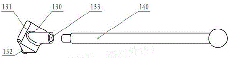
FIG. 3 is a schematic view of the handle attachment of the present invention;
FIG. 4 is an exploded view of the present invention;
FIG. 5 is a schematic view of a pullback baffle of the present invention;
in the figure: 100. the lifting device comprises a top iron, 101, a pull-back baffle plate, 102, a guide groove, 103, a lifting balance groove, 104, a limit locking stop, 104a, a rotating baffle plate, 105, a rotating shaft IV, 110, a split type clamping jaw clamping plate, 111, a lifting pin, 112, a guide pin, 113, a balance connecting pin, 114, a steel wire, 120, a lifting rod, 121, a rotating shaft I, 122, a hook head, 130, an equipotential lifting block, 131, a rotating shaft II, 132, a rotating shaft III, 133, a handle slot, 140, a handle, 150 and an oil cylinder.
Detailed Description
The clamping plate device of the equipotential pulling and splitting balanced push bench shown in fig. 1 to 5 comprises a top iron 100, wherein two split type clamping jaw clamping plates 110 are arranged on the top iron 100 and above an oil cylinder 150, the two split type clamping jaw clamping plates 110 are connected together through a balanced connecting pin 113, an opening limiting and guiding pin 112 is arranged on each split type clamping jaw clamping plate 110, each split type clamping jaw clamping plate 110 is connected with a handle 140 through a pulling device, a limiting device for fixing the handle 140 is arranged on each pulling device, the limiting device is arranged on the top iron 100, a pulling back baffle plate 101 is arranged on the outer side of each split type clamping jaw clamping plate 110, and a pulling balancing groove 103 and a guiding groove 102 which are matched with the balanced connecting pin 113 and the guiding pin 112 are arranged on the pulling back baffle plate 101. The opening limit is a straight chamfer arranged at the upper end of the split clamping jaw clamping plate 110. The invention relates to an equipotential pulling splitting balanced pipe jacking machine clamping plate device, wherein a top iron is provided with a left shoulder and a right shoulder, a front vertical surface and a rear vertical surface are provided with a hole in the middle, the lower parts of the left shoulder and the right shoulder are provided with groove-shaped openings for accommodating oil cylinders, a pull-back baffle is arranged on the top iron, a split type clamping jaw clamping plate is arranged between the top iron and the pull-back baffle and is arranged above the oil cylinders, the split type clamping jaw clamping plate is in a half horseshoe shape and is connected through a balanced connecting pin, an opening limit is arranged above the split type clamping jaw clamping plate and is a straight-edge chamfer arranged above the split type clamping jaw clamping plate and is positioned at one side opposite to the two split type clamping jaw clamping plates, when the two split type clamping jaw clamping plates rotate around the balanced connecting pin, the respective straight-edge chamfers gradually approach until the split type clamping jaw clamping plate is tightly attached, the split type clamping jaw clamping plate does not rotate any more, and the opening limit is convenient for the two split type clamping jaw clamping plates to open, the opening angles of the two split type clamping jaw clamping plates can be limited; the split type clamping jaw clamping plate is also provided with a guide pin, and the pull-back baffle plate is provided with a pull-up balance groove and a guide groove for the balance connecting pin and the guide pin to move; the split type clamping jaw clamping plates are connected with a handle through a traction device, the two split type clamping jaw clamping plates are lifted by the operating handle to be opened and lifted, a balance connecting pin slides up and down in a lifting balance groove, a guide pin slides up and down in a guide groove, the motion synchronism of the left split type clamping jaw clamping plate and the right split type clamping jaw clamping plate is ensured, the handles are pushed in place and then locked through a limiting device, the clamping plates can be kept in an opened state, at the moment, a group of clamping plate mechanisms are opened and lifted to the highest position, and the oil cylinder is not influenced to extend out and return in a top iron; the split type clamping jaw clamping plate can be automatically closed under the action of gravity, the oil cylinder retracts, and the pulling force of the oil cylinder is transmitted to the split type clamping jaw clamping plate, the retracting baffle and finally the top iron through the oil cylinder clamping ring, so that the top iron retracting function is realized; the invention can realize the function of moving the top iron back and forth without changing the state of the clamping plate, does not weaken the strength of the top iron, and has simple structure, reliable action and strong adaptability.
The equipotential pulling and splitting balanced pipe jacking machine clamping plate device shown in fig. 1 to 5 comprises a pulling connection part, a pulling rod 120 and an equipotential pulling block 130, wherein the equipotential pulling block 130 is connected with a handle 140, the equipotential pulling block 130 is connected with the pulling connection part through the pulling rod 120, and the pulling connection part is connected with a splitting clamping jaw clamping plate 110. The lifting connection part is a steel wire 114, and two ends of the steel wire 114 are respectively connected with each split type clamping jaw clamping plate 110 through a lifting pin 111. The lifting connection part is a connection rod, and two ends of the connection rod are respectively hinged with the lifting rod 120 and the split type clamping jaw clamping plate 110. The traction device comprises an equipotential lifting block, the equipotential lifting block is connected with a handle, a lifting rod is arranged below the equipotential lifting block and is connected with split type clamping jaw clamping plates through a lifting connecting part, the lifting connecting part is a steel wire or a connecting rod, when the steel wire is used, two ends of the steel wire are respectively connected with each split type clamping jaw clamping plate through lifting pins, and when the steel wire is used as the connecting rod, two ends of the connecting rod are respectively hinged with the lifting rod and the split type clamping jaw clamping plates; promote the handle, the lifting rod is pulled and is carried the steel wire and drive the subdivision formula clamping jaw cardboard and open, subdivision formula clamping jaw cardboard top has and opens spacingly, balanced connecting pin is located the lifting balance groove that draws back the baffle, two subdivision formula clamping jaw cardboards can be drawn in step and open, carry the lifting force that carries the steel wire to every subdivision formula clamping jaw cardboard to be the same, carry and draw in-process uide pin synchronous slip in the guide way that draws back the baffle, so carry and draw the process balanced.
As shown in fig. 1 to 5, the equipotential lifting and splitting balanced push bench clamping plate device is characterized in that the equipotential lifting block 130 is in the shape of an isosceles right triangular prism, a handle slot 133 is arranged on an inclined surface of the triangular prism, a rotating shaft iii 132 and a rotating shaft ii 131 are respectively arranged on a right-angled edge line and an acute-angled edge line at the bottom of the triangular prism, and an axis of the handle slot 133 is perpendicular to axes of the rotating shaft iii 132 and the rotating shaft ii 131. The upper end of the lifting rod 120 is provided with a rotating shaft I121 matched with the rotating shaft II 131 for use, and the lower end of the lifting rod 120 is provided with a hook head 122 connected with a lifting connecting part. The limiting device comprises a limiting locking stop 104 and a rotary baffle 104a, wherein a rotating shaft IV 105 matched with a rotating shaft III 132 for use is arranged on the limiting locking stop 104. The equipotential pulling block is an isosceles right triangle prism, the rotating shaft II is positioned on a ridge line where the bottom edge of the isosceles triangle is positioned, the rotating shaft III is positioned on a ridge line where the vertex of the isosceles triangle is positioned, the handle slot is positioned on a rectangle of the triangular prism, the axis direction of the handle is vertical to the axis directions of the rotating shaft II and the rotating shaft III, and the handle can be used by inserting and pulling force in the handle slot; the projection of the equipotential lifting block on the side surface of the top iron is an equilateral right-angled triangle, a rotating shaft III is connected with a rotating shaft IV on the shoulder part of the top iron, when the split type clamping jaw clamping plate is closed, the bevel edge of the projection triangle on the side surface of the equipotential lifting block is in a vertical state, when the split type clamping jaw clamping plate is opened and lifted to the maximum, the bevel edge is in a horizontal state, a rotating shaft II in the equipotential lifting block is connected with a rotating shaft I in a lifting rod, and the lifting rod is connected with the split type clamping jaw clamping plate through a hook head, a lifting steel wire and a lifting pin; the split type clamping jaw clamping plate is opened to a highest position and a closed position, a connecting line of projection points of the center of the rotating shaft II on the side surface of the top iron is in a vertical state, and the distances of the split type clamping jaw clamping plate relative to the vertical surface of the top iron before and after lifting are not changed, namely equipotential lifting is carried out; the limiting and locking stop blocks are arranged at the tops of the left shoulder and the right shoulder of the top iron and have two functions, namely, the handle is pushed, the split type clamping jaw is opened, and limiting is provided for the equipotential lifting block; secondly, after the position is limited, the equipotential pulling block and the position-limiting locking stop block are locked together by using the rotary baffle; the hook head can rotate freely around the axis of the lifting rod.
As shown in fig. 1 to 5, the working principle of the present invention is as follows:
when no lifting force acts on the split type clamping jaw clamping plate 110, the split type clamping jaw clamping plate 110 is in a closed state under the action of gravity and self limiting; the handle 140 is pushed, the equipotential pull block 130 rotates around the rotating shaft III 132, the rotating shaft II 131 drives the pull rod 120 to move upwards, the hook head 122 in the pull rod 120 pulls the pull steel wire 114, the pull steel wire 114 drives the split type clamping jaw clamping plate 110 to open through the pull pin 111, after the split type clamping jaw clamping plate 110 opens to a limit position, the pull steel wire 114 continues to pull, so that the balance connecting pin 113 in the split type clamping jaw clamping plate 110 rises along the pull balancing groove 103, the top end of the pull balancing groove 103 is used for pulling limit, meanwhile, the guide pin 112 slides in the guide groove 102, the split type clamping jaw clamping plate 110 is prevented from overturning, when the balance connecting pin 113 rises to the top end of the pull balancing groove 103, the equipotential pull block 130 is locked with the limit locking stop block 104, at the moment, a group of clamping plate mechanisms opens and lifts to the highest, and the oil cylinder 150 does not influence stretching and retracting in the top iron 100.
Claims (8)
1. The utility model provides an equipotential is carried and is drawn subdivision balanced type pipe push bench cardboard device which characterized in that: including top iron (100), the position that lies in hydro-cylinder (150) top on top iron (100) is equipped with two subdivision formula clamping jaw cardboard (110), and two subdivision formula clamping jaw cardboard (110) link together through balanced connecting pin (113), be equipped with on subdivision formula clamping jaw cardboard (110) and open spacing and uide pin (112), subdivision formula clamping jaw cardboard (110) are connected with handle (140) through draw-off device, the stop device that is equipped with fixed handle (140) on the draw-off device, stop device sets up on top iron (100), the outside of subdivision formula clamping jaw cardboard (110) is equipped with back and draws baffle (101), be equipped with on back and draw on baffle (101) and carry with balanced connecting pin (113) and uide pin (112) cooperation use and draw equilibrium groove (103) and guide way (102).
2. The clamping plate device of the equipotential lifting and splitting balanced push bench of claim 1, wherein: the drawing device comprises a drawing connecting part, a drawing rod (120) and an equipotential drawing block (130), the equipotential drawing block (130) is connected with a handle (140), the equipotential drawing block (130) is connected with the drawing connecting part through the drawing rod (120), and the drawing connecting part is connected with a split type clamping jaw clamping plate (110).
3. The clamping plate device of the equipotential lifting and splitting balanced push bench of claim 2, wherein: the lifting connection part is a steel wire (114), and two ends of the steel wire (114) are respectively connected with each split type clamping jaw clamping plate (110) through lifting pins (111).
4. The clamping plate device of the equipotential lifting and splitting balanced push bench of claim 2, wherein: the lifting connecting part is a connecting rod, and two ends of the connecting rod are respectively hinged with the lifting rod (120) and the split type clamping jaw clamping plate (110).
5. The clamping plate device of the equipotential lifting and splitting balanced push bench of claim 2, wherein: equipotential is carried and is drawn piece (130) and be isosceles right angle triangle prism shape, be equipped with handle slot (133) on the inclined plane of triangular prism, be equipped with pivot III (132) and pivot II (131) on the right angle crest line and the acute angle crest line of triangular prism bottom respectively, the axis of handle slot (133) is perpendicular with the axis of pivot III (132) and pivot II (131).
6. The clamping plate device of the equipotential lifting and splitting balanced push bench of claim 5, wherein: the upper end of the lifting rod (120) is provided with a rotating shaft I (121) matched with the rotating shaft II (131) for use, and the lower end of the lifting rod (120) is provided with a hook head (122) connected with a lifting connecting part.
7. The clamping plate device of the equipotential lifting and splitting balanced push bench of claim 5, wherein: the limiting device comprises a limiting locking stop block (104) and a rotary baffle plate (104 a), wherein a rotating shaft IV (105) matched with the rotating shaft III (132) for use is arranged on the limiting locking stop block (104).
8. The clamping plate device of the equipotential lifting and splitting balanced push bench of claim 1, wherein: the opening limit is a straight edge chamfer arranged at the upper end of the split type clamping jaw clamping plate (110).
Priority Applications (1)
| Application Number | Priority Date | Filing Date | Title |
|---|---|---|---|
| CN202111267416.6A CN113944805B (en) | 2021-10-29 | 2021-10-29 | Clamping plate device of equipotential lifting split balanced pipe jacking machine |
Applications Claiming Priority (1)
| Application Number | Priority Date | Filing Date | Title |
|---|---|---|---|
| CN202111267416.6A CN113944805B (en) | 2021-10-29 | 2021-10-29 | Clamping plate device of equipotential lifting split balanced pipe jacking machine |
Publications (2)
| Publication Number | Publication Date |
|---|---|
| CN113944805A true CN113944805A (en) | 2022-01-18 |
| CN113944805B CN113944805B (en) | 2023-05-12 |
Family
ID=79336995
Family Applications (1)
| Application Number | Title | Priority Date | Filing Date |
|---|---|---|---|
| CN202111267416.6A Active CN113944805B (en) | 2021-10-29 | 2021-10-29 | Clamping plate device of equipotential lifting split balanced pipe jacking machine |
Country Status (1)
| Country | Link |
|---|---|
| CN (1) | CN113944805B (en) |
Citations (11)
| Publication number | Priority date | Publication date | Assignee | Title |
|---|---|---|---|---|
| JPH08184294A (en) * | 1994-12-27 | 1996-07-16 | Iseki Tory Tech Inc | Pipe thrusting device |
| US20060034666A1 (en) * | 2004-08-11 | 2006-02-16 | Wentworth Steven W | Rod pulling and pushing machine for pipe bursting |
| WO2013070203A2 (en) * | 2011-11-09 | 2013-05-16 | Sumner Manufacturing Co.,Inc. | Clamp assembly |
| CN204036448U (en) * | 2014-07-11 | 2014-12-24 | 杨雪云 | A kind of collecting device |
| CN206290225U (en) * | 2016-11-08 | 2017-06-30 | 徐工集团工程机械有限公司 | A kind of multifunctional drill clamper |
| CN209229130U (en) * | 2018-10-26 | 2019-08-09 | 中交第四公路工程局有限公司 | A kind of circular top iron applied to pipe-jacking with large diameter construction |
| CN110541966A (en) * | 2019-08-27 | 2019-12-06 | 北京住总集团有限责任公司 | pipe joint jacking auxiliary equipment in narrow space and using method thereof |
| CN110778358A (en) * | 2019-10-28 | 2020-02-11 | 煤科集团沈阳研究院有限公司 | Modularized main roof equipment for rescuing collapsed coal mine roadway and assembling method thereof |
| CN212297913U (en) * | 2020-05-11 | 2021-01-05 | 广州市市政工程监理有限公司 | Mechanism is laid to town road spool |
| US20210095565A1 (en) * | 2019-09-27 | 2021-04-01 | Dalian University Of Technology | Rapid construction method of pipe jacking for underground rescue tunnel with large section |
| CN213773153U (en) * | 2020-11-20 | 2021-07-23 | 武汉商学院 | Novel special horse dung picking tool for horse yard |
-
2021
- 2021-10-29 CN CN202111267416.6A patent/CN113944805B/en active Active
Patent Citations (11)
| Publication number | Priority date | Publication date | Assignee | Title |
|---|---|---|---|---|
| JPH08184294A (en) * | 1994-12-27 | 1996-07-16 | Iseki Tory Tech Inc | Pipe thrusting device |
| US20060034666A1 (en) * | 2004-08-11 | 2006-02-16 | Wentworth Steven W | Rod pulling and pushing machine for pipe bursting |
| WO2013070203A2 (en) * | 2011-11-09 | 2013-05-16 | Sumner Manufacturing Co.,Inc. | Clamp assembly |
| CN204036448U (en) * | 2014-07-11 | 2014-12-24 | 杨雪云 | A kind of collecting device |
| CN206290225U (en) * | 2016-11-08 | 2017-06-30 | 徐工集团工程机械有限公司 | A kind of multifunctional drill clamper |
| CN209229130U (en) * | 2018-10-26 | 2019-08-09 | 中交第四公路工程局有限公司 | A kind of circular top iron applied to pipe-jacking with large diameter construction |
| CN110541966A (en) * | 2019-08-27 | 2019-12-06 | 北京住总集团有限责任公司 | pipe joint jacking auxiliary equipment in narrow space and using method thereof |
| US20210095565A1 (en) * | 2019-09-27 | 2021-04-01 | Dalian University Of Technology | Rapid construction method of pipe jacking for underground rescue tunnel with large section |
| CN110778358A (en) * | 2019-10-28 | 2020-02-11 | 煤科集团沈阳研究院有限公司 | Modularized main roof equipment for rescuing collapsed coal mine roadway and assembling method thereof |
| CN212297913U (en) * | 2020-05-11 | 2021-01-05 | 广州市市政工程监理有限公司 | Mechanism is laid to town road spool |
| CN213773153U (en) * | 2020-11-20 | 2021-07-23 | 武汉商学院 | Novel special horse dung picking tool for horse yard |
Also Published As
| Publication number | Publication date |
|---|---|
| CN113944805B (en) | 2023-05-12 |
Similar Documents
| Publication | Publication Date | Title |
|---|---|---|
| CN113944805A (en) | Equipotential lifting and splitting balanced type pipe jacking machine clamping plate device | |
| CN112320649B (en) | Foldable deep groove cable lifting device | |
| CN211847072U (en) | Wheel type well lid opening device based on lever principle | |
| CN205891957U (en) | Hoist and mount slip table | |
| CN210265358U (en) | Movable hydraulic station | |
| CN206263977U (en) | A kind of robot composite fixture | |
| CN212652975U (en) | Tool for disassembling transmission shaft | |
| CN213104575U (en) | Porous bench drilling machine for section bar opening | |
| CN216030568U (en) | Split type hydraulic puller fixing device | |
| CN214725369U (en) | Interior decoration is with portable cutting all-in-one that punches | |
| CN216335656U (en) | Automatic spreading machine | |
| CN212242317U (en) | Positioning device for hydraulic device | |
| CN217570722U (en) | Upset structure of equipment is forged freely | |
| CN218025091U (en) | Hoist device is used in workshop fitment | |
| CN210525098U (en) | Power-assisted manipulator | |
| CN214928580U (en) | Multifunctional automatic installation, oil injection and marking device for vehicle frame steel bowl | |
| CN219990996U (en) | Lock catch structure of folding crane | |
| CN212011926U (en) | Hoisting frame for electric power construction | |
| CN218932685U (en) | Quick positioning structure for tailoring | |
| CN210253463U (en) | Cleaning mechanism of full-automatic affinity purifier | |
| CN211914990U (en) | Be used for rolling pipe owner frame locking device | |
| CN215168856U (en) | Outdoor power cabinet door plate | |
| CN217692291U (en) | Portable electricity inspection auxiliary device | |
| CN220331160U (en) | Die carrier guide pin bushing assembly fixture | |
| CN215240819U (en) | Portable device is used in new energy automobile quick maintenance |
Legal Events
| Date | Code | Title | Description |
|---|---|---|---|
| PB01 | Publication | ||
| PB01 | Publication | ||
| SE01 | Entry into force of request for substantive examination | ||
| SE01 | Entry into force of request for substantive examination | ||
| GR01 | Patent grant | ||
| GR01 | Patent grant |