CN113942856B - Multifunctional paper feeder for paper printing - Google Patents
Multifunctional paper feeder for paper printing Download PDFInfo
- Publication number
- CN113942856B CN113942856B CN202111246893.4A CN202111246893A CN113942856B CN 113942856 B CN113942856 B CN 113942856B CN 202111246893 A CN202111246893 A CN 202111246893A CN 113942856 B CN113942856 B CN 113942856B
- Authority
- CN
- China
- Prior art keywords
- bracket
- frame
- conveying
- paper
- assembly
- Prior art date
- Legal status (The legal status is an assumption and is not a legal conclusion. Google has not performed a legal analysis and makes no representation as to the accuracy of the status listed.)
- Active
Links
Images


Classifications
-
- B—PERFORMING OPERATIONS; TRANSPORTING
- B65—CONVEYING; PACKING; STORING; HANDLING THIN OR FILAMENTARY MATERIAL
- B65H—HANDLING THIN OR FILAMENTARY MATERIAL, e.g. SHEETS, WEBS, CABLES
- B65H3/00—Separating articles from piles
- B65H3/02—Separating articles from piles using friction forces between articles and separator
- B65H3/06—Rollers or like rotary separators
- B65H3/0638—Construction of the rollers or like rotary separators
-
- B—PERFORMING OPERATIONS; TRANSPORTING
- B65—CONVEYING; PACKING; STORING; HANDLING THIN OR FILAMENTARY MATERIAL
- B65H—HANDLING THIN OR FILAMENTARY MATERIAL, e.g. SHEETS, WEBS, CABLES
- B65H1/00—Supports or magazines for piles from which articles are to be separated
- B65H1/08—Supports or magazines for piles from which articles are to be separated with means for advancing the articles to present the articles to the separating device
-
- B—PERFORMING OPERATIONS; TRANSPORTING
- B65—CONVEYING; PACKING; STORING; HANDLING THIN OR FILAMENTARY MATERIAL
- B65H—HANDLING THIN OR FILAMENTARY MATERIAL, e.g. SHEETS, WEBS, CABLES
- B65H29/00—Delivering or advancing articles from machines; Advancing articles to or into piles
- B65H29/20—Delivering or advancing articles from machines; Advancing articles to or into piles by contact with rotating friction members, e.g. rollers, brushes, or cylinders
-
- B—PERFORMING OPERATIONS; TRANSPORTING
- B65—CONVEYING; PACKING; STORING; HANDLING THIN OR FILAMENTARY MATERIAL
- B65H—HANDLING THIN OR FILAMENTARY MATERIAL, e.g. SHEETS, WEBS, CABLES
- B65H5/00—Feeding articles separated from piles; Feeding articles to machines
- B65H5/02—Feeding articles separated from piles; Feeding articles to machines by belts or chains, e.g. between belts or chains
- B65H5/021—Feeding articles separated from piles; Feeding articles to machines by belts or chains, e.g. between belts or chains by belts
-
- B—PERFORMING OPERATIONS; TRANSPORTING
- B65—CONVEYING; PACKING; STORING; HANDLING THIN OR FILAMENTARY MATERIAL
- B65H—HANDLING THIN OR FILAMENTARY MATERIAL, e.g. SHEETS, WEBS, CABLES
- B65H5/00—Feeding articles separated from piles; Feeding articles to machines
- B65H5/06—Feeding articles separated from piles; Feeding articles to machines by rollers or balls, e.g. between rollers
- B65H5/066—Feeding articles separated from piles; Feeding articles to machines by rollers or balls, e.g. between rollers the articles resting on rollers or balls
-
- B—PERFORMING OPERATIONS; TRANSPORTING
- B65—CONVEYING; PACKING; STORING; HANDLING THIN OR FILAMENTARY MATERIAL
- B65H—HANDLING THIN OR FILAMENTARY MATERIAL, e.g. SHEETS, WEBS, CABLES
- B65H5/00—Feeding articles separated from piles; Feeding articles to machines
- B65H5/08—Feeding articles separated from piles; Feeding articles to machines by grippers, e.g. suction grippers
-
- B—PERFORMING OPERATIONS; TRANSPORTING
- B65—CONVEYING; PACKING; STORING; HANDLING THIN OR FILAMENTARY MATERIAL
- B65H—HANDLING THIN OR FILAMENTARY MATERIAL, e.g. SHEETS, WEBS, CABLES
- B65H5/00—Feeding articles separated from piles; Feeding articles to machines
- B65H5/36—Article guides or smoothers, e.g. movable in operation
-
- B—PERFORMING OPERATIONS; TRANSPORTING
- B65—CONVEYING; PACKING; STORING; HANDLING THIN OR FILAMENTARY MATERIAL
- B65H—HANDLING THIN OR FILAMENTARY MATERIAL, e.g. SHEETS, WEBS, CABLES
- B65H2701/00—Handled material; Storage means
- B65H2701/10—Handled articles or webs
- B65H2701/11—Dimensional aspect of article or web
- B65H2701/113—Size
- B65H2701/1131—Size of sheets
Abstract
The invention discloses a multifunctional paper feeder for paper printing, which comprises a paper lifting assembly, a conveying assembly and an access assembly, wherein the paper lifting assembly comprises a first bracket, one end of the first bracket is provided with the conveying assembly, the conveying assembly comprises a second bracket, a second conveying frame with adjustable height is arranged in the second bracket, a receiving assembly is arranged above the second conveying frame, a third conveying frame and a fourth conveying frame are arranged at the upper end of the second bracket, a paper pushing assembly is fixedly arranged below the third conveying frame, one end of the second bracket is provided with the access assembly, the access assembly comprises a fourth bracket, a fifth slidable bracket is arranged in the fourth bracket, and tensioning and adjusting assemblies are arranged in the fourth bracket and the fifth bracket. The multifunctional paper feeder adopts a paper feeding and paper collecting integrated bidirectional conveying design, has small occupied space, can automatically adjust the length and angle of the in-out assembly according to the actual use situation, can meet the in-out material requirements of different printers, and has good overall applicability.
Description
Technical Field
The invention relates to the technical field of printing, in particular to a multifunctional paper feeder for paper printing.
Background
Printing devices are machines for printing text and images. Modern printing devices generally consist of mechanisms such as plate loading, inking, stamping, paper feeding, etc. The working principle of the printing device is that characters and images to be printed are made into printing plates, then the printing plates are arranged on a printing machine, then ink is coated on places with the characters and the images on the printing plates by manpower or the printing machine, and then the printing plates are directly or indirectly transferred onto paper or other printing stock, so that the printed matter identical to the printing plates is copied. In the existing printing device, paper printing mostly adopts unidirectional conveying, the occupied space is larger, or the paper is manually taken away after printing is finished, the labor cost is high, and because the internal mechanisms of each printing machine are different, the conveying line stretches into different lengths, the conventional design is used for moving the position of the conveying line, the length of the conveying line is manually adjusted, and the whole printing and conveying process is not automatic enough. In view of this situation, a multi-function paper feeder for paper printing is now proposed.
Disclosure of Invention
The invention aims to provide a multifunctional paper feeder for paper printing, which can effectively solve the defects in the background technology.
The aim of the invention can be achieved by the following technical scheme:
the multifunctional paper feeder comprises a paper lifting assembly, a conveying assembly and an in-out assembly, wherein the paper lifting assembly comprises a first support, one end of the first support is provided with the conveying assembly, the conveying assembly comprises a second support, a second conveying frame with adjustable height is arranged in the second support, a material receiving assembly is arranged above the second conveying frame and comprises a third support, a scraping plate is arranged below the third support, a third conveying frame and a fourth conveying frame are arranged at the upper end of the second support, a paper pushing assembly is fixedly arranged below the third conveying frame and comprises a guide plate, a connecting rod is arranged on one side of the guide plate, first mounting plates distributed in an array are arranged on the guide plate and the connecting rod, a movable pushing plate is arranged above the first mounting plates, pushing blocks distributed in an array are arranged on the pushing plate, a third cylinder is arranged on one side of the pushing plate, and a telescopic end of the third cylinder is fixedly connected with the pushing plate;
the second support one end is equipped with the subassembly that comes in and goes out, and the subassembly that comes in includes the fourth support, is equipped with slidable fifth support in the fourth support, is equipped with tensioning adjustment assembly in fourth support and the fifth support, tensioning adjustment assembly includes the fourth conveyer belt, fourth conveyer belt and fourth electronic roller and the electronic roller normal running fit of fifth, and backup pad, sliding plate are installed in the fourth conveyer belt, are equipped with tensioning roller and remove the roller on the fourth conveyer belt.
Further, a first lifting frame capable of lifting is arranged in the first bracket, a first installation block and a first bearing seat are symmetrically distributed at the upper end of the first bracket, a first rotating wheel in rotating connection is arranged in the first installation block, a first rotating shaft in rotating connection is arranged in the first bearing seat, a first motor is arranged at one end of the first rotating shaft, the first motor drives the first rotating shaft to rotate, a second rotating wheel in fixed connection is arranged on the first rotating shaft, and a first synchronous belt in rotating fit is arranged on the second rotating wheel and the first rotating wheel;
the upper end of the first bracket is also provided with a movable transverse moving frame, the transverse moving frame is fixedly connected with the first synchronous belt, and the first synchronous belt drives the transverse moving frame to move when rotating;
a first conveying frame is fixedly arranged above the first lifting frame, first electric rollers distributed in an array are arranged in the first conveying frame, and first conveying belts in running fit are arranged on the first electric rollers;
a first cylinder is fixedly arranged on one side of the transverse moving frame, the telescopic end below the first cylinder is fixedly connected with a second cylinder, the telescopic end below the second cylinder is fixedly connected with a first mounting frame, a paper feeding roller which is rotationally connected is arranged in the first mounting frame, one end of the paper feeding roller is provided with a second motor, the second motor drives the paper feeding roller to rotate, one side of the first bracket is provided with a coil, a rope in the coil is fixedly connected with the first lifting frame, and one end of the coil is provided with a third motor.
Further, be equipped with the electronic roller of array distribution in the second carriage, third support and second support fixed connection are equipped with array distribution, rotate the second pivot of connection in the third support, are equipped with the fourth motor on the third support, and the fourth motor drives the second pivot and rotates, drives the scraper blade and remove when the second pivot rotates.
Further, the third conveying frame and the fourth conveying frame are internally provided with third electric rollers which are distributed in an array mode, and the third electric rollers are provided with second conveying belts which are connected in a rotating mode.
Further, a power assembly is arranged between the third conveying frame and the fourth conveying frame, the power assembly comprises a fifth conveying frame, a third rotating wheel which is distributed in an array is arranged on one side of the fifth conveying frame, a fourth rotating wheel which is distributed in an array is arranged on the other side of the fifth conveying frame, a third conveying belt is arranged on the fourth rotating wheel and the third rotating wheel, a fifth motor is arranged at one end of the third rotating shaft, and the fifth motor drives the third conveying belt to rotate.
Further, one end of the fourth support is provided with a fourth electric roller, a supporting plate is arranged between the fourth supports, one end of the fifth support is provided with a fifth electric roller, a sliding plate is arranged in the fifth support, and the sliding plate slides in the supporting plate.
Further, be equipped with the first electric jar that rotates the connection below the fourth support, fourth support one end both sides all are equipped with the turning block that rotates the connection, and the turning block below is equipped with fixed connection's second electric jar, and the flexible end of second electric jar drives the turning block and descends to drive the decline of fourth support one end, the angle of fourth support and the height of the other end are adjusted to first electric jar.
Further, fourth support top is equipped with mobilizable board subassembly of getting, get the board subassembly and include sixth support, sixth support top is equipped with symmetrical distribution's first lead screw, all be equipped with first lead screw slider on the first lead screw, first lead screw one end all is equipped with seventh motor, be equipped with the movable plate on the first lead screw slider, the fixed fourth cylinder that is equipped with on the movable plate, sixth support one side is equipped with eighth motor, be equipped with fixed connection's third gear in the eighth motor axis of rotation, one side is equipped with the fourth gear of swivelling joint in the sixth support, third gear and fourth gear engagement, fourth gear and first rack engagement.
Further, be equipped with the fifth cylinder of array distribution below the fourth support, the flexible end of fifth cylinder is fixed to be equipped with the sucking disc, and fourth support one side is equipped with the second lead screw, is equipped with the second lead screw slider on the second lead screw, and the second lead screw upper end is equipped with ninth motor, and the fixed second crane that is equipped with on the second lead screw slider, second crane lower extreme both sides all are equipped with the pinch roller.
Further, tensioning roller rotates with fourth support to be connected, removes roller one side and is equipped with the movable frame, removes roller and movable frame and rotates to be connected, removes frame one side and is equipped with the mount, mount and fifth support fixed connection, removes frame one side and still fixedly to be equipped with the movable rod that runs through the mount, is equipped with the spring on the movable rod, spring one end and movable rod base fixed connection, the spring other end and mount fixed connection.
The invention has the beneficial effects that:
1. the multifunctional paper feeder has the advantages that the structure is stable and reliable, the feeding and the discharging are accurate and quick, the automatic design is adopted, the printing and the feeding of paper can be automatically carried out, the paper can be quickly and effectively conveyed and separated by the paper feeding roller arranged in the paper lifting assembly, and the first conveying frame continues to ascend during the paper conveying, so that the overall coordination is good, and the paper jam phenomenon can not occur;
2. the multifunctional paper feeder adopts a paper feeding and paper collecting integrated bidirectional conveying design, has small occupied space, can automatically adjust the length and angle of the in-out assembly according to the actual use situation, can meet the in-out material requirements of different printers, has good overall applicability, and has high automation degree in the whole printing and conveying process.
Drawings
The invention is further described below with reference to the accompanying drawings.
FIG. 1 is a schematic diagram of a multi-function paper feeder of the present invention;
FIG. 2 is a schematic view of a paper lifting assembly according to the present invention;
FIG. 3 is an enlarged schematic view of the structure of FIG. 2A in accordance with the present invention;
FIG. 4 is an enlarged schematic view of the structure of FIG. 2B in accordance with the present invention;
FIG. 5 is an enlarged schematic view of the structure of FIG. 2 at C in accordance with the present invention;
FIG. 6 is a schematic view of the transport assembly of the present invention;
FIG. 7 is a schematic view of a portion of the structure of a conveyor assembly of the present invention;
FIG. 8 is a schematic view of a portion of the structure of a conveyor assembly of the present invention;
FIG. 9 is a schematic view of a portion of the structure of a conveyor assembly of the present invention;
FIG. 10 is a schematic view of a paper pushing assembly according to the present invention;
FIG. 11 is a schematic view of the material receiving assembly of the present invention;
FIG. 12 is a schematic view of the power assembly of the present invention;
FIG. 13 is a schematic view of the access module of the present invention;
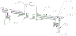
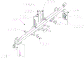
FIG. 14 is a schematic view of a portion of the structure of an access module according to the present invention;
FIG. 15 is a schematic view of a pick-up plate assembly according to the present invention;
FIG. 16 is a schematic view of a pick-up plate assembly according to the present invention;
fig. 17 is a schematic view of the tensioning adjustment assembly of the present invention.
Detailed Description
The following description of the embodiments of the present invention will be made clearly and completely with reference to the accompanying drawings, in which it is apparent that the embodiments described are only some embodiments of the present invention, but not all embodiments. All other embodiments, which can be made by those skilled in the art based on the embodiments of the invention without making any inventive effort, are intended to be within the scope of the invention.
In the description of the present invention, it should be understood that the terms "open," "upper," "lower," "thickness," "top," "middle," "length," "inner," "peripheral," and the like indicate orientation or positional relationships, merely for convenience in describing the present invention and to simplify the description, and do not indicate or imply that the components or elements referred to must have a particular orientation, be constructed and operated in a particular orientation, and thus should not be construed as limiting the present invention.
Referring to fig. 1 to 17, a multifunctional paper feeder for printing paper includes a paper lifting assembly 1, a conveying assembly 2, and an access assembly 3, wherein the paper lifting assembly 1 includes a first bracket 11, a first lifting frame 12, a first conveying frame 13, a traversing frame 15, and a paper feeding roller 183, the conveying assembly 2 includes a second bracket 21, a second conveying frame 22, a receiving assembly 23, a third conveying frame 24, a paper pushing assembly 25, a fourth conveying frame 26, and a power assembly 27, and the access assembly 3 includes a fourth bracket 31, a fifth bracket 32, a plate taking assembly 33, and a tension adjusting assembly 34.
The paper lifting assembly 1 comprises a first bracket 11, wherein first sliding rails 111 which are symmetrically distributed are arranged in the first bracket 11, first sliding blocks 112 which are in sliding fit are arranged on the first sliding rails 111, first lifting frames 12 are fixedly arranged on the first sliding blocks 112, first mounting blocks 113 and first bearing seats 114 which are symmetrically distributed are arranged at the upper ends of the first bracket 11, first rotating wheels 1131 which are rotationally connected are arranged in the first mounting blocks 113, first rotating shafts 17 which are rotationally connected are arranged in the first bearing seats 114, a first motor 171 is arranged at one end of each first rotating shaft 17, the first motor 171 drives the first rotating shafts 17 to rotate, second rotating wheels 16 which are fixedly connected are arranged on the first rotating shafts 17, and first synchronous belts 161 which are rotationally matched are arranged on the second rotating wheels 16 and the first rotating wheels 1131;
the upper end of the first bracket 11 is also provided with second sliding rails 14 which are symmetrically distributed, the second sliding rails 14 are provided with second sliding blocks 141 which are in sliding fit, the second sliding blocks 141 are fixedly provided with transverse moving frames 15, the transverse moving frames 15 are provided with first connecting blocks 151, the transverse moving frames 15 are fixedly connected with first synchronous belts 161 by the first connecting blocks 151, and the first synchronous belts 161 are driven to move when rotating;
a first conveying frame 13 is fixedly arranged above the first lifting frame 12, first electric rollers 132 distributed in an array are arranged in the first conveying frame 13, first auxiliary rollers 131 distributed in an array are arranged at two ends of each first electric roller 132, a first conveying belt 133 in running fit is arranged on each first electric roller 132, and papers to be conveyed are piled on the first conveying belts 133;
the first cylinder 18 is fixedly arranged on one side of the traversing rack 15, the telescopic end below the first cylinder 18 is fixedly connected with the second cylinder 181, the telescopic end below the second cylinder 181 is fixedly connected with the first mounting rack 182, the paper feeding roller 183 which is rotationally connected is arranged in the first mounting rack 182, a second motor 184 is arranged at one end of the paper feeding roller 183, the second motor 184 drives the paper feeding roller 183 to rotate, a coil 19 is arranged on one side of the first rack 11, a rope in the coil 19 is fixedly connected with the first lifting rack 12, a third motor 191 is arranged at one end of the coil 19, and the third motor 191 drives the coil 19 to rotate, so that the first lifting rack 12 is driven to lift.
One end of the first bracket 11 is provided with a conveying assembly 2, the conveying assembly 2 comprises a second bracket 21, a second conveying frame 22 with adjustable height is arranged in the second bracket 21, second electric rollers 221 distributed in an array are arranged in the second conveying frame 22, and a material receiving assembly 23 is arranged above the second conveying frame 22;
the material receiving assembly 23 comprises a third support 231, the third support 231 is fixedly connected with the second support 21, second rotating shafts 232 which are distributed in an array mode and are rotationally connected are arranged in the third support 231, first chain wheels 234 which are distributed in an array mode are arranged on the second rotating shafts 232, second chain wheels 233 are further arranged on one group of second rotating shafts 232, a fourth motor 235 is arranged on the third support 231, a third chain wheel 236 which is fixedly connected is arranged on a rotating shaft of the fourth motor 235, a first chain 237 which is rotationally connected is arranged on the second chain wheel 233 and the third chain wheel 236, a second chain 238 which is rotationally connected is arranged on the first chain wheel 234, third sliding rails 239 which are symmetrically distributed are arranged below the third support 231, third sliding blocks 2310 which are in sliding fit are arranged on the third sliding rails 239, scraping plates 2311 are fixedly arranged on the third sliding blocks 2310, and the scraping plates 2311 are fixedly connected with the second chain 238.
The upper end of the second bracket 21 is provided with a third conveying frame 24 and a fourth conveying frame 26, a paper pushing assembly 25 is fixedly arranged below the third conveying frame 24, second auxiliary rollers 241 which are symmetrically distributed in an array are arranged in the third conveying frame 24 and the fourth conveying frame 26, third electric rollers 242 which are distributed in an array are arranged between the second auxiliary rollers 241, and a second conveying belt 243 which is rotationally connected is arranged on the third electric rollers 242;
the paper pushing assembly 25 comprises a guide plate 251, a connecting rod 252 is arranged on one side of the guide plate 251, first mounting plates 253 distributed in an array are arranged on the guide plate 251 and the connecting rod 252, fourth sliding rails 254 are arranged on the first mounting plates 253, fourth sliding blocks 255 in sliding fit are arranged on the fourth sliding rails 254, a pushing plate 256 is fixedly arranged on the fourth sliding blocks 255, pushing blocks 258 distributed in an array are arranged on the pushing plate 256, a third air cylinder 257 is arranged on one side of the pushing plate 256, the third air cylinder 257 is fixedly arranged on the guide plate 251 and the connecting rod 252, and the telescopic ends of the third air cylinders 257 are fixedly connected with the pushing plate 256;
a power assembly 27 is arranged between the third conveying frame 24 and the fourth conveying frame 26, the power assembly 27 comprises a fifth conveying frame 271, a third rotating wheel 272 which is distributed in an array is arranged on one side of the fifth conveying frame 271, a second bearing seat 273 which is distributed in an array is arranged on the other side of the fifth conveying frame 271, a third rotating shaft 274 which is connected in a rotating mode is arranged in the second bearing seat 273, a fourth rotating wheel 275 which is distributed in an array and is fixedly connected is arranged on the third rotating shaft 274, a third conveying belt 276 is arranged on the fourth rotating wheel 275 and the third rotating wheel 272, a fifth motor 277 is arranged at one end of the third rotating shaft 274, and the fifth motor 277 drives the third rotating shaft 274 to rotate.
An access assembly 3 is arranged at one end of the second support 21, the access assembly 3 comprises a fourth support 31, a fourth electric roller 311 is arranged at one end of the fourth support 31, a sixth motor 312 is arranged at one side of the fourth support 31, fifth sliding rails 313 which are distributed in an array manner are arranged at two sides of the fourth support 31, fifth sliding blocks 314 which are in sliding fit are arranged on the fifth sliding rails 313, a first rack 315 is also arranged at the other side of the fourth support 31, a support plate 316 is arranged between the fourth supports 31, a fifth slidable support 32 is arranged in the fourth support 31, a fifth electric roller 321 is arranged at one end of the fifth support 32, a sliding plate 322 is arranged in the fifth support 32, the sliding plate 322 slides in the support plate 316, a second rack 323 is arranged at one side of the fifth support 32, a first gear 3121 is arranged on the rotating shaft of the sixth motor 312, a second gear 3122 which is connected in a rotating manner is arranged at one side of the fifth support 32, the first gear 3121 is meshed with the second gear 3122, and the second gear 3122 is meshed with the second rack 323;
a first electric cylinder 317 in rotary connection is arranged below the fourth bracket 31, rotary blocks 318 in rotary connection are arranged on two sides of one end of the fourth bracket 31, a second electric cylinder 319 in fixed connection is arranged below the rotary blocks 318, the telescopic end of the second electric cylinder 319 drives the rotary blocks 318 to descend, and accordingly one end of the fourth bracket 31 is driven to descend, and the first electric cylinder 317 adjusts the angle of the fourth bracket 31 and the height of the other end of the fourth bracket;
the movable plate taking assembly 33 is arranged above the fourth support 31, the plate taking assembly 33 comprises a sixth support 331, the sixth support 331 is fixedly matched with the fifth sliding block 314, first screw rods 332 which are symmetrically distributed are arranged above the sixth support 331, first screw rod sliding blocks 3321 are arranged on the first screw rods 332, a seventh motor 334 is arranged at one end of each first screw rod 332, a movable plate 333 is arranged on each first screw rod sliding block 3321, a fourth air cylinder 335 is fixedly arranged on each movable plate 333, an eighth motor 336 is arranged on one side of the sixth support 331, a third gear 3361 which is fixedly connected is arranged on a rotating shaft of the eighth motor 336, a fourth gear 3362 which is rotatably connected is arranged on one side in the sixth support 331, the third gear 3361 is meshed with the fourth gear 3362, and the fourth gear 3362 is meshed with the first rack 315;
a fifth air cylinder 337 distributed in an array is arranged below the fourth support 31, a sucking disc 3371 is fixedly arranged at the telescopic end of the fifth air cylinder 337, a second screw rod 338 is arranged on one side of the fourth support 31, a second screw rod sliding block 3381 is arranged on the second screw rod 338, a ninth motor 3382 is arranged at the upper end of the second screw rod 338, a second lifting frame 39 is fixedly arranged on the second screw rod sliding block 3381, and pressing wheels 3391 are arranged on two sides of the lower end of the second lifting frame 39;
the tensioning adjustment assembly 34 is arranged in the fourth bracket 31 and the fifth bracket 32, the tensioning adjustment assembly 34 comprises a fourth conveying belt 341, the fourth conveying belt 341 is in running fit with the fourth electric roller 311 and the fifth electric roller 321, a supporting plate 316 and a sliding plate 322 are arranged in the fourth conveying belt 341, a tensioning roller 342 and a moving roller 345 are arranged on the fourth conveying belt 341, the tensioning roller 342 is rotationally connected with the fourth bracket 31, a moving frame 344 is arranged on one side of the moving roller 345, the moving roller 345 is rotationally connected with the moving frame 344, a fixing frame 343 is arranged on one side of the moving frame 344, the fixing frame 343 is fixedly connected with the fifth bracket 32, a moving rod 356 penetrating through the fixing frame 343 is further fixedly arranged on one side of the moving frame 344, a spring 347 is arranged on the moving rod 356, one end of the spring 347 is fixedly connected with a base of the moving rod 356, and the other end of the spring 347 is fixedly connected with the fixing frame 343.
In use, the unprinted paper stacking state is placed on the first conveying belt 133, the wire reel 19 rotates to drive the first lifting frame 12 to lift, the first lifting frame 12 drives the first conveying frame 13 to lift, when the highest position of the stacked paper is equal to the height of the fourth conveying frame 26, the power assembly 27 and the third conveying frame 24, the first motor 171 drives the traversing frame 15 to move to the front end of the paper, the first cylinder 18 and the second cylinder 181 push the paper feeding roller 183 to descend to contact the paper at the highest position, the second motor 184 starts to drive the paper feeding roller 183 to rotate to drive the paper to advance, the first conveying frame 13 continues to lift when the paper is conveyed, the second conveying belt 243 and the third conveying belt 276 rotate, the paper reaches the position of the paper pushing assembly 25 to stop, the third cylinder 257 pushes the pushing block 258 to stretch out, the pushing block 258 drives the front end of the paper to be horizontal, the eighth motor 336 drives the paper taking assembly 33 to move forward, the fifth cylinder 337 pushes the suction cup 3371 to advance to suck the paper, then the eighth motor 336 drives the take-off plate assembly 33 to retreat, the paper is pulled to the fourth conveyor belt 341, the seventh motor 334 drives the fourth cylinder 335 to move, the telescopic end of the fourth cylinder 335 pushes, the paper is centered, the sixth motor 312 starts pushing out the sliding plate 322 according to the length inside the printer, the fourth conveyor belt 341 stretches, the spring 347 contracts, the moving frame 344 advances, the repeated operation is performed until the paper is completely printed, then the telescopic end of the second cylinder 319 drives the rotating block 318 to descend, thereby driving one end of the fourth bracket 31 to descend, one end of the fourth bracket 31 is contacted with the second conveyor frame 22 to stop, the first cylinder 317 adjusts the angle of the fourth bracket 31 and the height of the other end, the printed paper is reversely conveyed and conveyed to the second electric roller 221 through the fourth conveyor belt 341, the second motor roller 221 rotates to convey the paper to the center of the second conveying frame 22, and the fourth motor 235 is started to drive the scraper 2311 to move so as to push out the printed paper.
In the description of the present specification, the descriptions of the terms "one embodiment," "example," "specific example," and the like, mean that a particular feature, structure, material, or characteristic described in connection with the embodiment or example is included in at least one embodiment or example of the present invention. In this specification, schematic representations of the above terms do not necessarily refer to the same embodiments or examples. Furthermore, the particular features, structures, materials, or characteristics described may be combined in any suitable manner in any one or more embodiments or examples.
The foregoing has shown and described the basic principles, principal features and advantages of the invention. It will be understood by those skilled in the art that the present invention is not limited to the embodiments described above, and that the above embodiments and descriptions are merely illustrative of the principles of the present invention, and various changes and modifications may be made without departing from the spirit and scope of the invention, which is defined in the appended claims.
Claims (10)
1. The multifunctional paper feeder for paper printing comprises a paper lifting assembly (1), a conveying assembly (2) and an in-out assembly (3), and is characterized in that the paper lifting assembly (1) comprises a first bracket (11), one end of the first bracket (11) is provided with the conveying assembly (2), the conveying assembly (2) comprises a second bracket (21), a second conveying frame (22) with adjustable height is arranged in the second bracket (21), a material collecting assembly (23) is arranged above the second conveying frame (22), the material collecting assembly (23) comprises a third bracket (231), a scraping plate (2311) is arranged below the third bracket (231), a third conveying frame (24) and a fourth conveying frame (26) are arranged at the upper end of the second bracket (21), a paper pushing assembly (25) is fixedly arranged below the third conveying frame (24), the paper pushing assembly (25) comprises a guide plate (251), one side of the guide plate (251) is provided with a connecting rod (252), a first conveying frame (253) distributed in an array manner is arranged on the second bracket (21), a first pushing plate (253) distributed in an array manner is arranged above the connecting rod (252), a movable pushing plate (256) is arranged on the first pushing plate (256) and a first pushing plate (258) is provided with an array pushing plate (257), the telescopic end of the third air cylinder (257) is fixedly connected with the pushing plate (256);
one end of the second bracket (21) is provided with an access assembly (3), the access assembly (3) comprises a fourth bracket (31), a fifth slidable bracket (32) is arranged in the fourth bracket (31), tensioning and adjusting assemblies (34) are arranged in the fourth bracket (31) and the fifth bracket (32), the tensioning and adjusting assemblies (34) comprise a fourth conveying belt (341), the fourth conveying belt (341) is in running fit with the fourth electric roller (311) and the fifth electric roller (321), the supporting plate (316) and the sliding plate (322) are arranged in the fourth conveying belt (341), and the fourth conveying belt (341) is provided with a tensioning roller (342) and a moving roller (345).
2. The multifunctional paper feeder for paper printing according to claim 1, wherein a first lifting frame (12) capable of lifting is arranged in the first bracket (11), first installation blocks (113) and first bearing seats (114) which are symmetrically distributed are arranged at the upper end of the first bracket (11), first rotating wheels (1131) which are rotationally connected are arranged in the first installation blocks (113), first rotating shafts (17) which are rotationally connected are arranged in the first bearing seats (114), a first motor (171) is arranged at one end of each first rotating shaft (17), the first motor (171) drives the first rotating shafts (17) to rotate, second rotating wheels (16) which are fixedly connected are arranged on the first rotating shafts (17), and first synchronous belts (161) which are rotationally matched with the first rotating wheels (1131) are arranged on the second rotating wheels (16);
the upper end of the first bracket (11) is also provided with a movable transverse moving frame (15), the transverse moving frame (15) is fixedly connected with a first synchronous belt (161), and the first synchronous belt (161) drives the transverse moving frame (15) to move when rotating;
a first conveying frame (13) is fixedly arranged above the first lifting frame (12), first electric rollers (132) distributed in an array are arranged in the first conveying frame (13), and first conveying belts (133) in running fit are arranged on the first electric rollers (132);
the utility model discloses a paper feeding device, including sideslip frame (15), first cylinder (18), flexible end in first cylinder (18) below and second cylinder (181) fixed connection, flexible end in second cylinder (181) below and first mounting bracket (182) fixed connection, be equipped with in first mounting bracket (182) and rotate feed cylinder (183) of being connected, feed cylinder (183) one end is equipped with second motor (184), second motor (184) drive feed cylinder (183) rotation, first support (11) one side is equipped with coil of wire (19), rope and first crane (12) fixed connection in coil of wire (19), coil of wire (19) one end is equipped with third motor (191).
3. The multifunctional paper feeder for printing paper according to claim 1, wherein the second conveying frame (22) is internally provided with second electric rollers (221) distributed in an array, the third support (231) is fixedly connected with the second support (21), the third support (231) is internally provided with second rotating shafts (232) distributed in an array and connected in a rotating mode, the third support (231) is provided with a fourth motor (235), the fourth motor (235) drives the second rotating shafts (232) to rotate, and the second rotating shafts (232) drive the scraping plates (2311) to move when rotating.
4. The multifunctional paper feeder for printing paper according to claim 1, wherein the third conveying frame (24) and the fourth conveying frame (26) are respectively provided with third electric rollers (242) which are distributed in an array, and the third electric rollers (242) are provided with a second conveying belt (243) which is connected in a rotating way.
5. The multifunctional paper feeder for paper printing according to claim 1, wherein a power assembly (27) is arranged between the third conveying frame (24) and the fourth conveying frame (26), the power assembly (27) comprises a fifth conveying frame (271), a third rotating wheel (272) distributed in an array is arranged on one side of the fifth conveying frame (271), a fourth rotating wheel (275) distributed in an array is arranged on the other side of the fifth conveying frame (271), a third conveying belt (276) is arranged on the fourth rotating wheel (275) and the third rotating wheel (272), a fifth motor (277) is arranged at one end of the third rotating shaft (274), and the fifth motor (277) drives the third conveying belt (276) to rotate.
6. The multifunctional paper feeder for printing paper according to claim 1, wherein a fourth electric roller (311) is arranged at one end of the fourth bracket (31), a supporting plate (316) is arranged between the fourth brackets (31), a fifth electric roller (321) is arranged at one end of the fifth bracket (32), a sliding plate (322) is arranged in the fifth bracket (32), and the sliding plate (322) slides in the supporting plate (316).
7. The multifunctional paper feeder for printing paper according to claim 1, wherein a first electric cylinder (317) connected in a rotating manner is arranged below the fourth bracket (31), two sides of one end of the fourth bracket (31) are respectively provided with a rotating block (318) connected in a rotating manner, a second electric cylinder (319) connected in a fixed manner is arranged below the rotating blocks (318), the telescopic end of the second electric cylinder (319) drives the rotating blocks (318) to descend, and accordingly one end of the fourth bracket (31) is driven to descend, and the angle of the fourth bracket (31) and the height of the other end of the fourth bracket are adjusted by the first electric cylinder (317).
8. The multifunctional paper feeder for paper printing according to claim 1, wherein the movable board taking assembly (33) is arranged above the fourth support (31), the board taking assembly (33) comprises a sixth support (331), first lead screws (332) which are symmetrically distributed are arranged above the sixth support (331), first lead screw sliding blocks (3321) are arranged on the first lead screws (332), seventh motors (334) are arranged at one ends of the first lead screws (332), movable boards (333) are arranged on the first lead screw sliding blocks (3321), fourth air cylinders (335) are fixedly arranged on the movable boards (333), an eighth motor (336) is arranged on one side of the sixth support (331), a third gear (3361) which is fixedly connected is arranged on a rotating shaft of the eighth motor (336), fourth gears (3362) which are rotationally connected are arranged on one side in the sixth support (331), the third gears (3361) are meshed with the fourth gears (3362), and the fourth gears (3362) are meshed with the first racks (315).
9. The multifunctional paper feeder for paper printing according to claim 1, wherein a fifth cylinder (337) distributed in an array is arranged below the fourth support (31), a sucking disc (3371) is fixedly arranged at the telescopic end of the fifth cylinder (337), a second screw rod (338) is arranged on one side of the fourth support (31), a second screw rod sliding block (3381) is arranged on the second screw rod (338), a ninth motor (3382) is arranged at the upper end of the second screw rod (338), a second lifting frame (39) is fixedly arranged on the second screw rod sliding block (3381), and pinch rollers (3391) are arranged on two sides of the lower end of the second lifting frame (39).
10. The multifunctional paper feeder for paper printing according to claim 1, wherein the tension roller (342) is rotatably connected with the fourth bracket (31), a movable frame (344) is arranged on one side of the movable roller (345), the movable roller (345) is rotatably connected with the movable frame (344), a fixing frame (343) is arranged on one side of the movable frame (344), the fixing frame (343) is fixedly connected with the fifth bracket (32), a movable rod (356) penetrating the fixing frame (343) is fixedly arranged on one side of the movable frame (344), a spring (347) is arranged on the movable rod (356), one end of the spring (347) is fixedly connected with a base of the movable rod (356), and the other end of the spring (347) is fixedly connected with the fixing frame (343).
Priority Applications (1)
| Application Number | Priority Date | Filing Date | Title |
|---|---|---|---|
| CN202111246893.4A CN113942856B (en) | 2021-10-26 | 2021-10-26 | Multifunctional paper feeder for paper printing |
Applications Claiming Priority (1)
| Application Number | Priority Date | Filing Date | Title |
|---|---|---|---|
| CN202111246893.4A CN113942856B (en) | 2021-10-26 | 2021-10-26 | Multifunctional paper feeder for paper printing |
Publications (2)
| Publication Number | Publication Date |
|---|---|
| CN113942856A CN113942856A (en) | 2022-01-18 |
| CN113942856B true CN113942856B (en) | 2023-05-09 |
Family
ID=79332406
Family Applications (1)
| Application Number | Title | Priority Date | Filing Date |
|---|---|---|---|
| CN202111246893.4A Active CN113942856B (en) | 2021-10-26 | 2021-10-26 | Multifunctional paper feeder for paper printing |
Country Status (1)
| Country | Link |
|---|---|
| CN (1) | CN113942856B (en) |
Families Citing this family (1)
| Publication number | Priority date | Publication date | Assignee | Title |
|---|---|---|---|---|
| CN114481511B (en) * | 2022-01-20 | 2024-04-12 | 嘉兴市鸣业纺织有限公司 | Fabric imitation silk wrinkling device |
Citations (6)
| Publication number | Priority date | Publication date | Assignee | Title |
|---|---|---|---|---|
| JP2004142917A (en) * | 2002-10-28 | 2004-05-20 | Maruju Tekkosho:Kk | Laminating device |
| CN203865636U (en) * | 2014-05-27 | 2014-10-08 | 瑞安市荣庆包装机械厂 | Automatic paperboard turn-over mechanism |
| CN211812492U (en) * | 2019-12-30 | 2020-10-30 | 扬州皓宇图文印刷有限公司 | Paper conveying device with tensioning mechanism for printing machine |
| CN212216877U (en) * | 2020-04-21 | 2020-12-25 | 安徽新立滤清器有限公司 | Punching press automatic feeding device based on flexible coupling and pneumatic adsorption |
| CN213707143U (en) * | 2020-10-24 | 2021-07-16 | 郑州佳佳印务有限公司 | Automatic feeding device of sheet printing machine |
| CN214243147U (en) * | 2020-12-04 | 2021-09-21 | 杜志鹏 | Full-automatic paper collator |
Family Cites Families (1)
| Publication number | Priority date | Publication date | Assignee | Title |
|---|---|---|---|---|
| US20030014376A1 (en) * | 2001-07-13 | 2003-01-16 | Dewitt Robert R. | Method and apparatus for processing outgoing bulk mail |
-
2021
- 2021-10-26 CN CN202111246893.4A patent/CN113942856B/en active Active
Patent Citations (6)
| Publication number | Priority date | Publication date | Assignee | Title |
|---|---|---|---|---|
| JP2004142917A (en) * | 2002-10-28 | 2004-05-20 | Maruju Tekkosho:Kk | Laminating device |
| CN203865636U (en) * | 2014-05-27 | 2014-10-08 | 瑞安市荣庆包装机械厂 | Automatic paperboard turn-over mechanism |
| CN211812492U (en) * | 2019-12-30 | 2020-10-30 | 扬州皓宇图文印刷有限公司 | Paper conveying device with tensioning mechanism for printing machine |
| CN212216877U (en) * | 2020-04-21 | 2020-12-25 | 安徽新立滤清器有限公司 | Punching press automatic feeding device based on flexible coupling and pneumatic adsorption |
| CN213707143U (en) * | 2020-10-24 | 2021-07-16 | 郑州佳佳印务有限公司 | Automatic feeding device of sheet printing machine |
| CN214243147U (en) * | 2020-12-04 | 2021-09-21 | 杜志鹏 | Full-automatic paper collator |
Also Published As
| Publication number | Publication date |
|---|---|
| CN113942856A (en) | 2022-01-18 |
Similar Documents
| Publication | Publication Date | Title |
|---|---|---|
| CN113942856B (en) | Multifunctional paper feeder for paper printing | |
| CN113120565B (en) | Conveying device of towel printing machine | |
| CN216610473U (en) | Full-automatic screen printing machine | |
| CN210418634U (en) | Printing output device | |
| CN113401567B (en) | Charging tray conveying device | |
| CN213325922U (en) | Feeding deviation correcting device of printing machine | |
| CN212219428U (en) | Paper feeding mechanism of full-automatic book-shaped box assembling machine | |
| CN114872432A (en) | Automatic change integrative equipment of hot pressing rendition and tectorial membrane | |
| CN212445465U (en) | Cutting device is used in corrugated paper production | |
| CN211225610U (en) | Paper feeding mechanism of printing machine | |
| CN213798700U (en) | A adjustable impression equipment for books and periodicals magazine printing | |
| CN216548779U (en) | Printing is with incessant paper supply rail set | |
| CN218477288U (en) | Production is with hard board positioning printing machine | |
| CN218809375U (en) | Printing delivery aligning device | |
| CN220808872U (en) | High-speed automatic printing machine convenient to adjust belt height | |
| CN215042925U (en) | A handling device for printed matter coiled material | |
| CN220810904U (en) | Automatic plate feeding mechanism | |
| CN220466494U (en) | Automatic board collecting machine for camera production | |
| CN218505473U (en) | Multi-station printing machine | |
| CN214732962U (en) | Tray adjusting mechanism of printing machine | |
| CN214878763U (en) | Paper transfer device for paper printing | |
| CN211545457U (en) | Printed matter folding device | |
| CN217170264U (en) | Remove and paste cloth device | |
| CN219823049U (en) | Printing machine feed mechanism | |
| CN213593929U (en) | Automatic general loading attachment of regulation formula and printing machine |
Legal Events
| Date | Code | Title | Description |
|---|---|---|---|
| PB01 | Publication | ||
| PB01 | Publication | ||
| SE01 | Entry into force of request for substantive examination | ||
| SE01 | Entry into force of request for substantive examination | ||
| GR01 | Patent grant | ||
| GR01 | Patent grant |