CN113939752A - Optical module, isolator-equipped socket, and optical module - Google Patents
Optical module, isolator-equipped socket, and optical module Download PDFInfo
- Publication number
- CN113939752A CN113939752A CN202080037910.0A CN202080037910A CN113939752A CN 113939752 A CN113939752 A CN 113939752A CN 202080037910 A CN202080037910 A CN 202080037910A CN 113939752 A CN113939752 A CN 113939752A
- Authority
- CN
- China
- Prior art keywords
- ferrule
- optical
- core
- isolator
- optical fiber
- Prior art date
- Legal status (The legal status is an assumption and is not a legal conclusion. Google has not performed a legal analysis and makes no representation as to the accuracy of the status listed.)
- Pending
Links
- 230000003287 optical effect Effects 0.000 title claims abstract description 127
- 230000010287 polarization Effects 0.000 claims abstract description 63
- 239000000758 substrate Substances 0.000 claims abstract description 9
- 239000013307 optical fiber Substances 0.000 claims description 60
- MCMNRKCIXSYSNV-UHFFFAOYSA-N Zirconium dioxide Chemical compound O=[Zr]=O MCMNRKCIXSYSNV-UHFFFAOYSA-N 0.000 claims description 28
- 239000000463 material Substances 0.000 claims description 23
- 238000005253 cladding Methods 0.000 claims description 16
- 229920005989 resin Polymers 0.000 claims description 14
- 239000011347 resin Substances 0.000 claims description 14
- 239000000919 ceramic Substances 0.000 claims description 13
- 239000000853 adhesive Substances 0.000 description 21
- 230000001070 adhesive effect Effects 0.000 description 20
- 239000013078 crystal Substances 0.000 description 13
- 239000000843 powder Substances 0.000 description 13
- 239000000835 fiber Substances 0.000 description 10
- 239000011521 glass Substances 0.000 description 8
- 239000010935 stainless steel Substances 0.000 description 7
- 229910001220 stainless steel Inorganic materials 0.000 description 7
- 239000004925 Acrylic resin Substances 0.000 description 6
- 229920000178 Acrylic resin Polymers 0.000 description 6
- 239000003822 epoxy resin Substances 0.000 description 6
- 238000004519 manufacturing process Methods 0.000 description 6
- 229920000647 polyepoxide Polymers 0.000 description 6
- 239000011812 mixed powder Substances 0.000 description 5
- 238000005498 polishing Methods 0.000 description 5
- 238000004891 communication Methods 0.000 description 4
- 238000000034 method Methods 0.000 description 4
- 238000000465 moulding Methods 0.000 description 4
- 229920001707 polybutylene terephthalate Polymers 0.000 description 4
- RUDFQVOCFDJEEF-UHFFFAOYSA-N yttrium(III) oxide Inorganic materials [O-2].[O-2].[O-2].[Y+3].[Y+3] RUDFQVOCFDJEEF-UHFFFAOYSA-N 0.000 description 4
- GWEVSGVZZGPLCZ-UHFFFAOYSA-N Titan oxide Chemical compound O=[Ti]=O GWEVSGVZZGPLCZ-UHFFFAOYSA-N 0.000 description 3
- KPLQYGBQNPPQGA-UHFFFAOYSA-N cobalt samarium Chemical compound [Co].[Sm] KPLQYGBQNPPQGA-UHFFFAOYSA-N 0.000 description 3
- 230000001419 dependent effect Effects 0.000 description 3
- 239000002223 garnet Substances 0.000 description 3
- 238000010438 heat treatment Methods 0.000 description 3
- 229910052751 metal Inorganic materials 0.000 description 3
- 239000002184 metal Substances 0.000 description 3
- 239000012778 molding material Substances 0.000 description 3
- 229910000938 samarium–cobalt magnet Inorganic materials 0.000 description 3
- VYPSYNLAJGMNEJ-UHFFFAOYSA-N silicon dioxide Inorganic materials O=[Si]=O VYPSYNLAJGMNEJ-UHFFFAOYSA-N 0.000 description 3
- YCKRFDGAMUMZLT-UHFFFAOYSA-N Fluorine atom Chemical compound [F] YCKRFDGAMUMZLT-UHFFFAOYSA-N 0.000 description 2
- 239000005062 Polybutadiene Substances 0.000 description 2
- XUIMIQQOPSSXEZ-UHFFFAOYSA-N Silicon Chemical compound [Si] XUIMIQQOPSSXEZ-UHFFFAOYSA-N 0.000 description 2
- -1 Yttrium Vanadates Chemical class 0.000 description 2
- 230000002159 abnormal effect Effects 0.000 description 2
- 238000010521 absorption reaction Methods 0.000 description 2
- PNEYBMLMFCGWSK-UHFFFAOYSA-N aluminium oxide Inorganic materials [O-2].[O-2].[O-2].[Al+3].[Al+3] PNEYBMLMFCGWSK-UHFFFAOYSA-N 0.000 description 2
- JNDMLEXHDPKVFC-UHFFFAOYSA-N aluminum;oxygen(2-);yttrium(3+) Chemical compound [O-2].[O-2].[O-2].[Al+3].[Y+3] JNDMLEXHDPKVFC-UHFFFAOYSA-N 0.000 description 2
- 230000000694 effects Effects 0.000 description 2
- 239000011737 fluorine Substances 0.000 description 2
- 229910052731 fluorine Inorganic materials 0.000 description 2
- LNEPOXFFQSENCJ-UHFFFAOYSA-N haloperidol Chemical compound C1CC(O)(C=2C=CC(Cl)=CC=2)CCN1CCCC(=O)C1=CC=C(F)C=C1 LNEPOXFFQSENCJ-UHFFFAOYSA-N 0.000 description 2
- 238000005259 measurement Methods 0.000 description 2
- 229920006122 polyamide resin Polymers 0.000 description 2
- 229920002857 polybutadiene Polymers 0.000 description 2
- 229920005668 polycarbonate resin Polymers 0.000 description 2
- 239000004431 polycarbonate resin Substances 0.000 description 2
- 238000012545 processing Methods 0.000 description 2
- 239000004065 semiconductor Substances 0.000 description 2
- 229910052710 silicon Inorganic materials 0.000 description 2
- 239000010703 silicon Substances 0.000 description 2
- 235000012239 silicon dioxide Nutrition 0.000 description 2
- 229920002050 silicone resin Polymers 0.000 description 2
- 229920002803 thermoplastic polyurethane Polymers 0.000 description 2
- 125000000391 vinyl group Chemical group [H]C([*])=C([H])[H] 0.000 description 2
- 229920002554 vinyl polymer Polymers 0.000 description 2
- 229910019901 yttrium aluminum garnet Inorganic materials 0.000 description 2
- 229910021532 Calcite Inorganic materials 0.000 description 1
- 229910052688 Gadolinium Inorganic materials 0.000 description 1
- 229910052689 Holmium Inorganic materials 0.000 description 1
- 229910052771 Terbium Inorganic materials 0.000 description 1
- QVGXLLKOCUKJST-UHFFFAOYSA-N atomic oxygen Chemical compound [O] QVGXLLKOCUKJST-UHFFFAOYSA-N 0.000 description 1
- 239000011230 binding agent Substances 0.000 description 1
- 230000015556 catabolic process Effects 0.000 description 1
- 238000009694 cold isostatic pressing Methods 0.000 description 1
- 238000010276 construction Methods 0.000 description 1
- 238000005520 cutting process Methods 0.000 description 1
- 238000005238 degreasing Methods 0.000 description 1
- 238000001739 density measurement Methods 0.000 description 1
- 238000009826 distribution Methods 0.000 description 1
- 238000001125 extrusion Methods 0.000 description 1
- 230000004907 flux Effects 0.000 description 1
- 238000000227 grinding Methods 0.000 description 1
- 238000001746 injection moulding Methods 0.000 description 1
- 238000003780 insertion Methods 0.000 description 1
- 230000037431 insertion Effects 0.000 description 1
- 238000002955 isolation Methods 0.000 description 1
- 238000003754 machining Methods 0.000 description 1
- 238000002156 mixing Methods 0.000 description 1
- 238000012986 modification Methods 0.000 description 1
- 230000004048 modification Effects 0.000 description 1
- 239000003921 oil Substances 0.000 description 1
- 229910052760 oxygen Inorganic materials 0.000 description 1
- 239000001301 oxygen Substances 0.000 description 1
- BPUBBGLMJRNUCC-UHFFFAOYSA-N oxygen(2-);tantalum(5+) Chemical compound [O-2].[O-2].[O-2].[O-2].[O-2].[Ta+5].[Ta+5] BPUBBGLMJRNUCC-UHFFFAOYSA-N 0.000 description 1
- 230000000149 penetrating effect Effects 0.000 description 1
- 230000002093 peripheral effect Effects 0.000 description 1
- 239000013308 plastic optical fiber Substances 0.000 description 1
- 239000010453 quartz Substances 0.000 description 1
- 229910052594 sapphire Inorganic materials 0.000 description 1
- 239000010980 sapphire Substances 0.000 description 1
- 238000000926 separation method Methods 0.000 description 1
- 239000000377 silicon dioxide Substances 0.000 description 1
- 239000000126 substance Substances 0.000 description 1
- PBCFLUZVCVVTBY-UHFFFAOYSA-N tantalum pentoxide Inorganic materials O=[Ta](=O)O[Ta](=O)=O PBCFLUZVCVVTBY-UHFFFAOYSA-N 0.000 description 1
- 239000004408 titanium dioxide Substances 0.000 description 1
- OGIDPMRJRNCKJF-UHFFFAOYSA-N titanium oxide Inorganic materials [Ti]=O OGIDPMRJRNCKJF-UHFFFAOYSA-N 0.000 description 1
- 238000003466 welding Methods 0.000 description 1
- 229910052727 yttrium Inorganic materials 0.000 description 1
Images


Classifications
-
- G—PHYSICS
- G02—OPTICS
- G02B—OPTICAL ELEMENTS, SYSTEMS OR APPARATUS
- G02B6/00—Light guides; Structural details of arrangements comprising light guides and other optical elements, e.g. couplings
- G02B6/24—Coupling light guides
- G02B6/36—Mechanical coupling means
- G02B6/38—Mechanical coupling means having fibre to fibre mating means
- G02B6/3807—Dismountable connectors, i.e. comprising plugs
- G02B6/381—Dismountable connectors, i.e. comprising plugs of the ferrule type, e.g. fibre ends embedded in ferrules, connecting a pair of fibres
- G02B6/3812—Dismountable connectors, i.e. comprising plugs of the ferrule type, e.g. fibre ends embedded in ferrules, connecting a pair of fibres having polarisation-maintaining light guides
-
- G—PHYSICS
- G02—OPTICS
- G02B—OPTICAL ELEMENTS, SYSTEMS OR APPARATUS
- G02B6/00—Light guides; Structural details of arrangements comprising light guides and other optical elements, e.g. couplings
- G02B6/24—Coupling light guides
- G02B6/36—Mechanical coupling means
- G02B6/38—Mechanical coupling means having fibre to fibre mating means
- G02B6/3807—Dismountable connectors, i.e. comprising plugs
- G02B6/3833—Details of mounting fibres in ferrules; Assembly methods; Manufacture
- G02B6/3853—Lens inside the ferrule
-
- G—PHYSICS
- G02—OPTICS
- G02B—OPTICAL ELEMENTS, SYSTEMS OR APPARATUS
- G02B6/00—Light guides; Structural details of arrangements comprising light guides and other optical elements, e.g. couplings
- G02B6/24—Coupling light guides
- G02B6/26—Optical coupling means
- G02B6/27—Optical coupling means with polarisation selective and adjusting means
- G02B6/2746—Optical coupling means with polarisation selective and adjusting means comprising non-reciprocal devices, e.g. isolators, FRM, circulators, quasi-isolators
-
- G—PHYSICS
- G02—OPTICS
- G02B—OPTICAL ELEMENTS, SYSTEMS OR APPARATUS
- G02B6/00—Light guides; Structural details of arrangements comprising light guides and other optical elements, e.g. couplings
- G02B6/24—Coupling light guides
- G02B6/36—Mechanical coupling means
- G02B6/38—Mechanical coupling means having fibre to fibre mating means
- G02B6/3807—Dismountable connectors, i.e. comprising plugs
- G02B6/381—Dismountable connectors, i.e. comprising plugs of the ferrule type, e.g. fibre ends embedded in ferrules, connecting a pair of fibres
- G02B6/3826—Dismountable connectors, i.e. comprising plugs of the ferrule type, e.g. fibre ends embedded in ferrules, connecting a pair of fibres characterised by form or shape
- G02B6/3829—Bent or angled connectors
-
- G—PHYSICS
- G02—OPTICS
- G02B—OPTICAL ELEMENTS, SYSTEMS OR APPARATUS
- G02B6/00—Light guides; Structural details of arrangements comprising light guides and other optical elements, e.g. couplings
- G02B6/24—Coupling light guides
- G02B6/36—Mechanical coupling means
- G02B6/38—Mechanical coupling means having fibre to fibre mating means
- G02B6/3807—Dismountable connectors, i.e. comprising plugs
- G02B6/3833—Details of mounting fibres in ferrules; Assembly methods; Manufacture
- G02B6/3854—Ferrules characterised by materials
-
- G—PHYSICS
- G02—OPTICS
- G02B—OPTICAL ELEMENTS, SYSTEMS OR APPARATUS
- G02B6/00—Light guides; Structural details of arrangements comprising light guides and other optical elements, e.g. couplings
- G02B6/24—Coupling light guides
- G02B6/36—Mechanical coupling means
- G02B6/38—Mechanical coupling means having fibre to fibre mating means
- G02B6/3807—Dismountable connectors, i.e. comprising plugs
- G02B6/3873—Connectors using guide surfaces for aligning ferrule ends, e.g. tubes, sleeves, V-grooves, rods, pins, balls
- G02B6/3885—Multicore or multichannel optical connectors, i.e. one single ferrule containing more than one fibre, e.g. ribbon type
-
- G—PHYSICS
- G02—OPTICS
- G02B—OPTICAL ELEMENTS, SYSTEMS OR APPARATUS
- G02B27/00—Optical systems or apparatus not provided for by any of the groups G02B1/00 - G02B26/00, G02B30/00
- G02B27/30—Collimators
Landscapes
- Physics & Mathematics (AREA)
- General Physics & Mathematics (AREA)
- Optics & Photonics (AREA)
- Optical Couplings Of Light Guides (AREA)
Abstract
The optical module of the present disclosure includes: a 1 st ferrule having a 1 st collimating lens; and a 2 nd ferrule having a 2 nd collimator lens, and a polarization-independent optical isolator is provided between the 1 st ferrule and the 2 nd ferrule. The disclosed isolator-equipped socket is provided with: the above optical module; and a receptacle connected to the optical module. The optical module of the present disclosure includes: the above isolator-equipped socket; and an external substrate connected to the isolator-equipped socket.
Description
CROSS-REFERENCE TO RELATED APPLICATIONS
This application claims priority from japanese patent application No. 2019-100407 (application No. 5/29/2019), the disclosure of which is incorporated herein by reference in its entirety.
Technical Field
The present disclosure relates to an optical module, an isolator-equipped receptacle, and an optical module used in optical communication and the like, using a polarization-independent optical isolator having a function of reducing return light from the outside.
Background
Semiconductor lasers (hereinafter referred to as LDs) are used in optical communication systems, optical measurement systems, and the like. It is known that, when an LD is used, a part of light is reflected, and the LD is damaged by incidence of the reflected light, i.e., return light, on an active layer of the LD. Further, it is known that a breakdown of the internal interference state causes a wavelength shift or a fluctuation in output. In order to protect the LD from the return light, to realize high-precision measurement, communication under high-speed modulation, and high-density measurement, an optical isolator having a function of passing forward light and reducing the return light is used.
Optical isolators are classified into polarization-dependent optical isolators and polarization-independent optical isolators according to the difference in the method of reducing the return light. The polarization dependent optical isolator transmits polarized light having a specific polarization plane in the forward direction, and reduces the generation of return light by rotating the polarization plane. On the other hand, the polarization-independent optical isolator separates polarized light into normal light and abnormal light without affecting the polarization plane, and transmits polarized light components in the forward direction by utilizing the difference in the optical paths of the normal light and the abnormal light, thereby reducing the return light. The latter polarization-dependent optical isolator has a structure with a low insertion loss and high versatility because it does not affect the polarization plane. An example of using a polarization-independent optical isolator in an optical communication system is disclosed in cited document 1 (japanese unexamined patent application publication No. 11-174382).
Disclosure of Invention
The optical module of the present disclosure includes: a 1 st ferrule having a 1 st collimating lens; and a 2 nd ferrule having a 2 nd collimator lens, and a polarization-independent optical isolator is provided between the 1 st ferrule and the 2 nd ferrule.
The disclosed isolator-equipped socket is provided with: the optical module of the above structure; and a receptacle connected to the optical module.
The optical module of the present disclosure includes: the isolator-equipped socket of the above configuration; and an external substrate connected to the isolator-equipped socket.
Drawings
Fig. 1 is a perspective view of an optical module according to embodiment 1 of the present disclosure.
Fig. 2 is a cross-sectional view of an optical module according to embodiment 1 of the present disclosure.
Fig. 3 is a cross-sectional view of an optical module according to embodiment 2 of the present disclosure.
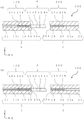
Fig. 4 is a cross-sectional view of an optical module according to embodiment 3 of the present disclosure.
Fig. 5 is a perspective view of the socket with isolator according to embodiment 4 of the present disclosure.
Fig. 6 is a sectional view of a socket with an isolator according to embodiment 4 of the present disclosure.
Fig. 7 is a perspective view of an optical module according to embodiment 5 of the present disclosure.
Detailed Description
The embodiments are described in detail below with reference to the drawings.
< Structure of optical Module 1 >
As shown in fig. 1, the optical module 10 of the present disclosure includes a 1 st ferrule 1, a 2 nd ferrule 2, and a polarization-independent optical isolator 3.
The 1 st ferrule 1 has, for example, a cylindrical shape or a square tubular shape. The size of the No. 1 ferrule 1 is, for example, the diameter The length is 2.0 mm-10 mm. In fig. 1, optical fibers are shown at
 reference numerals 11, 12.
As shown in fig. 2, the 1 st ferrule 1 includes a 1 st end portion 12, a 2 nd end portion 13, and a 1 st through hole 10 that penetrates the 1 st end portion 12 and the 2 nd end portion 13. Here, the light traveling direction is the X-axis direction in fig. 2, and light from an external light source such as an LD enters an opening provided at the 1 st end portion 12, passes through the 1 st through hole 10, and exits from an opening located at the 2 nd end portion 13. Light from an external light source such as an LD may be directly incident into the 1 st through hole 10, or may be incident into the 1 st through hole 10 via the optical fiber 11. Fig. 2 (a) to (c) show an example in which a 1 st collimator lens 14 is provided in the 1 st through hole 10 in the vicinity of the 2 nd end 13. As such, with the optical module 100 of the present disclosure, the 1 st ferrule 1 has the 1 st collimating lens 14. The 1 st collimator lens 14 outputs a substantially parallel light beam.
Examples of the material constituting the 1 st ferrule 1 include zirconia ceramics, alumina ceramics, glass, and the like. Here, for example, the term "zirconia ceramic" refers to a ceramic containing zirconia (ZrO)2) The ceramic as the main component is a component containing 80 mass% or more of 100 mass% of all components constituting the ceramic. The same applies to alumina ceramics. When the material of the 1 st ferrule 1 is zirconia ceramics, it can be used for a long period of time because of its high mechanical strength and excellent wear resistance. When the material of the 1 st ferrule 1 is glass, it can be visually checked whether the 1 st collimator lens 14 and the like located in the 1 st through hole 10 are located at the correct positions.
When the 1 st ferrule 1 has a cylindrical shape, the 1 st through hole 10 may be concentric with the outer shape and may linearly extend. When such a configuration is satisfied, the optical axis can be adjusted without considering the position of the through hole with respect to the outer shape and the direction in which the through hole extends, and therefore, the optical axis of light passing through the inside of the 1 st through hole 10 can be easily adjusted.
When an external light source is incident into the 1 st through hole 10, an optical fiber 11 having an outer diameter of 125 μm defined in JIS standard or TIA/EIA standard may be used. The size of the diameter of the 1 st through hole 10 can be determined as appropriate for the value specified by the specification. The size of the diameter of the 1 st through hole 10 is, for example Determined by the diameter of the optical fiber used. Examples of the
 optical fiber 11 include a quartz optical fiber, a plastic optical fiber, and a multicomponent glass optical fiber. The optical fiber 11 is inserted into the 1 st through hole 10 from the 1 st end 12 side of the 1 st ferrule 1, and the 1 st through hole 10 is filled with adhesiveAgent 8 to anchor cuff 1.
As the adhesive 8, for example, acrylic resin, epoxy resin, vinyl resin, silicone resin, urethane resin, polyamide resin, fluorine resin, polybutadiene resin, polycarbonate resin, or the like can be used. Among the above materials, acrylic resins and epoxy resins are excellent in moisture resistance, heat resistance, peeling resistance and impact resistance.
As shown in fig. 2 (d), the 1 st end 12 of the 1 st ferrule 1 may have a tapered shape with a wider opening side with respect to the inside of the 1 st ferrule 1 in a cross-sectional view in the X-axis direction. As shown in fig. 2 (e), the edge of the opening on the 1 st end 12 side may be a shape with a corner removed. When such a configuration is satisfied, the 1 st collimator lens 14 and the optical fiber 11 are easily inserted into the 1 st through hole 10. In addition, the adhesive 8 for fixing the optical fiber 11 is easily inserted. The 1 st collimator lens 14 is connected to the optical fiber 11 in advance and then inserted into the 1 st through hole 10. Therefore, the 1 st through hole 10 is provided with the optical fiber 11 and the 1 st collimator lens 14 in this order in the light traveling direction. At this time, the 1 st collimator lens 14 may be located at the opening of the 2 nd end portion 13.
The 1 st surface 13a of the 2 nd end 13 of the 1 st ferrule 1 may be a flat surface as shown in fig. 2 (a), for example. The 1 st surface 13a is a surface located in the vicinity of the 2 nd ferrule 2. When the 1 st surface 13a is a plane, the polarization-independent optical isolator 4 is easily provided. The 1 st surface 13a may be a plane inclined with respect to the light traveling direction. The plane inclined with respect to the light traveling direction is, for example, a plane inclined in a range of 2 ° to 12 ° with respect to the Z-axis direction, which is a direction perpendicular to the X-axis direction, when viewed in a cross section in the X-axis direction as shown in fig. 2 (b). When the 1 st surface 13a is a plane inclined with respect to the light traveling direction, the optical axis of the reflected light on the 1 st surface 13a is inclined, and therefore the reflected light on the 1 st surface 13a is coupled to the 3 rd core 11a of the 1 st optical fiber 11, and becomes less return light.
A 1 st transparent member 15 may be attached to the 1 st collimator lens 14. In this case, the 1 st collimator lens 14 and the 1 st transparent member 15 may be provided in the 1 st through hole 10 in this order in the X-axis direction, and the 1 st transparent member 15 may be positioned at the opening of the 2 nd end portion 13. When the 1 st transparent member 15 is positioned at the opening of the 2 nd end portion 13, when the 1 st surface 13a is formed by polishing the 2 nd end portion 13, powder generated by polishing hardly enters the 1 st through hole 10, and absorption or reflection of light by the entering powder is small, so that loss of light amount is less likely to occur. The 1 st collimator lens 14 and the 1 st transparent member 15 may be joined by an adhesive 8 or may be fused by heat treatment.
The material of the 1 st transparent member 15 may be glass. When such a configuration is satisfied, if an acrylic resin or an epoxy resin is used as the adhesive 8 whenever the polarization independent optical isolator 4 is bonded to the 1 st surface 13a, the refractive indices of the glass and the acrylic resin or the epoxy resin are close to each other, and therefore, reflected light is less generated between the glass and the adhesive 8.
The 1 st collimator lens 14 is a lens having a property of obtaining a substantially parallel light flux, and when it is positioned in the 1 st through hole 10, for example, a multimode fiber of a graded index type (GI) can be used as the 1 st collimator lens 14. The GI multimode fiber continuously changes the refractive index, and outputs substantially parallel light according to the refractive index distribution, and thus functions as a collimator lens. Therefore, by using the GI multimode fiber, the optical module 100 can be made smaller than when a collimator lens is disposed. When the 1 st collimator lens 14 is a GI multi-mode fiber and the 1 st transparent member 15 is glass, the values of the refractive indexes of the GI multi-mode fiber and the glass are close to each other, and therefore, reflected light is less likely to be generated and return light is less likely to be generated.
The description of the shape, size, and material of the 2 nd ferrule 2 is the same as those described above with respect to the 1 st ferrule 1, and therefore, is omitted. As shown in FIG. 2, the 2 nd ferrule 2 has a 3 rd end portion 22, a 4 th end portion 23, and a 2 nd through hole 20 penetrating the 3 rd end portion 22 and the 4 th end portion 23. Here, light enters from the opening located at the 3 rd end portion 22, passes through the 2 nd through hole, and exits from the opening located at the 4 th end portion 23. Fig. 2 (a) to (c) show an example in which a 2 nd collimator lens 24 is provided in the 2 nd through hole 20 in the vicinity of the 3 rd end 22. As described above, in the optical module 100 of the present disclosure, the 2 nd ferrule 2 includes the 2 nd collimator lens 24.
The description of the shape of the 2 nd through hole 20 is the same as that described above with respect to the 1 st through hole 10, and therefore, is omitted.
The 4 th end 23 of the 2 nd ferrule 2 may be tapered such that the opening side thereof is wider with respect to the inside of the 2 nd ferrule 2, as in the 1 st end 12 shown in fig. 2 (d). As shown in fig. 2 (e), the edge of the opening on the 4 th end 23 side may be a shape with a corner removed, as in the 1 st end 12. When such a configuration is satisfied, the 2 nd collimator lens 24 and the optical fiber 21 are easily inserted into the 2 nd through hole 20. In addition, the adhesive 8 for fixing the optical fiber 21 is easily inserted. The 2 nd collimator lens 24 is inserted after being connected to the optical fiber 21 in advance. Therefore, the 2 nd through hole 20 is provided with the 2 nd collimator lens 24 and the optical fiber 21 in this order in the light traveling direction. In this case, the 2 nd collimator lens 24 may be located at the opening of the 3 rd end 22.
The 2 nd surface 22a of the 3 rd end 22 of the 2 nd ferrule 2 may be a flat surface as shown in fig. 2 (a), for example. The 2 nd surface 22a is a surface located in the vicinity of the 1 st ferrule 1. In the case of a plane, it is easy to provide the polarization-independent optical isolator 4. The 2 nd surface 22a may be a plane inclined with respect to the traveling direction of light. The plane inclined with respect to the light traveling direction is, for example, a plane inclined in a range of 2 ° to 12 ° with respect to the Z-axis direction, which is a direction perpendicular to the X-axis direction, when viewed in a cross section in the X-axis direction as shown in fig. 2 (b). When the 2 nd surface 22a is a plane inclined with respect to the traveling direction of light, the optical axis of the reflected light on the 2 nd surface 22a is inclined, and therefore the reflected light on the 2 nd surface 22a is coupled to the 1 st optical fiber 11 and becomes return light in a small amount.
In the 2 nd collimator lens 24, a 2 nd transparent member 25 may be connected. In this case, the 2 nd transparent member 25 and the 2 nd collimator lens 24 may be positioned in the 2 nd through hole 20 in this order, and the 2 nd transparent member 25 may be positioned at the opening of the 3 rd end 22 in the X-axis direction. When the 2 nd transparent member 25 is positioned at the opening of the 3 rd end portion 22, when the 3 rd end portion 22 is subjected to end surface processing to form the 2 nd surface 22a, powder generated by polishing hardly enters the 2 nd through hole 20, and absorption or reflection of light by the entering powder is small, so that loss of light amount is less likely to occur. The 2 nd collimator lens 24 and the 2 nd transparent member 25 may be joined by an adhesive 8 or may be fused by heat treatment.
The description of the material of the 2 nd transparent member 25, the 2 nd collimator lens 24, and the optical fiber 21 is the same as the description of the 1 st transparent member 15, the 1 st collimator lens 14, and the optical fiber 11, and therefore, is omitted.
The 1 st ferrule 1 and the 2 nd ferrule 2 may be independent of each other. Thus, the alignment can be performed by moving the 2 nd ferrule 2 so that the light coming out from the opening on the 2 nd end 13 side of the 1 st through hole 10 in the 1 st ferrule 1 is incident into the 2 nd through hole 20. The 1 st surface 13a of the 1 st ferrule 1 and the 2 nd surface 22a of the 2 nd ferrule 2 may be arranged in parallel or may not be arranged in parallel. In this case, the optical axis can be adjusted by arranging the 1 st surface 13a of the 1 st ferrule 1 and the 2 nd surface 22a of the 2 nd ferrule 2 in parallel, in such a manner that the 1 st through hole 10 of the 1 st ferrule 1 extends concentrically and linearly with respect to the outer shape, the 2 nd through hole 20 of the 2 nd ferrule 2 extends concentrically and linearly with respect to the outer shape, and the angle between the 1 st surface 13a and the 1 st through hole 10 and the angle between the 2 nd surface 22a and the 2 nd through hole 20 are adjusted to be different angles.
< method for producing ferrule >
An example of the method for manufacturing the 1 st ferrule 1 will be described below. In this example, an example will be described in which the material of the 1 st ferrule 1 is zirconia ceramics containing zirconia as a main component. The method for producing the 2 nd ferrule 2 is also the same as the method for producing the 1 st ferrule 1.
First, a mixed powder of zirconia powder and yttria powder is sufficiently mixed and pulverized by a ball mill or the like, and then a binder is added to the pulverized product and the resultant is mixed to obtain a molding material. The mixed powder is, for example, a powder obtained by mixing 85 to 99 mass% of zirconia powder and 1 to 15 mass% of yttria powder, out of 100 mass% of the mixed powder. The mixed powder may be 90 to 99% by mass of zirconia powder, 1 to 10% by mass of yttria powder, 95 to 99% by mass of zirconia powder, and 1 to 5% by mass of yttria powder, among 100% by mass of the mixed powder.
Next, a molded body having a shape similar to the final shape and a through hole is formed using the prepared molding material. Specifically, a cavity of a molding die capable of obtaining a shape similar to the final shape is filled with a molding material, and press molding is performed at a predetermined pressure, thereby obtaining a molded body. The method for obtaining the molded body is not limited to the above press molding, and a method such as injection molding, cast molding, cold isostatic pressing, or extrusion molding may be used.
Next, the obtained compact is fired to obtain a sintered body. Specifically, the obtained molded body is degreased by being put into a degreasing furnace at 500 to 600 ℃ for 2 to 10 hours, and then the degreased molded body is fired at 1300 to 1500 ℃ for 0.5 to 3 hours in an oxygen atmosphere, thereby obtaining a sintered body.
Next, the outer periphery of the obtained sintered body and the inner peripheral surface of the through hole are subjected to polishing or the like to form the 1 st end 12, the 2 nd end 13, and the 1 st through hole 10. Specifically, the machining is performed by pushing a grindstone while rotating the sintered body. In this case, the polishing can be performed while suppressing an increase in roughness of the polished surface by using the grinding oil. The ferrule 1 can be manufactured as described above.
Next, the polarization-independent optical isolator 4 is, for example, a square prism shape. The end face may be a plane with an inclination. In the case where the polarization independent optical isolator 4 is provided in the 2 nd end portion 13, the 1 st through hole 10 in the 1 st ferrule 1 may extend linearly and concentrically with respect to the outer shape, the 1 st surface 13a in the 2 nd end portion 13 may be a plane with a tilt, and the end surface of the polarization independent optical isolator 4 may be tilted so as to be parallel to the 1 st surface 13 a. This makes it easy to provide the polarization-independent optical isolator 4 on the 1 st surface 13 a. The polarization independent optical isolator 4 has a mounting surface with a size in a range of 0.2mm to 1.5mm in the vertical direction and 0.2mm to 1.5mm in the horizontal direction, for example, and has a length in the optical axis direction in a range of 1.0mm to 2.5 mm.
The polarization independent optical isolator 4 is configured by bonding a 1 st birefringent crystal 41, a faraday rotator 42, a 1/2 wavelength plate 43, and a 2 nd birefringent crystal 44 as shown in fig. 4 (a) and (b). In this case, the faraday rotator 42 and the 1/2 wavelength plate 43 are sandwiched between the 1 st birefringent crystal 41 and the 2 nd birefringent crystal 44, respectively, but the order of the faraday rotator 42 and the 1/2 wavelength plate 43 may be set in front of either direction of the traveling path of the light. The antireflection material may be located between the 1 st birefringent crystal 41, the faraday rotator 42, the 1/2 wavelength plate 43, and the 2 nd birefringent crystal 44, respectively. This can reduce reflected light at the surface (interface) of the boundary between the members. Although the antireflection material is provided at the interface, the drawing is complicated, and hence no reference numeral is given to the drawing.
The polarization independent optical isolator 4 is located on the forward path of light exiting from the opening on the 2 nd end 13 side of the 1 st through hole 10 and is located at the 2 nd end 13 of the 1 st ferrule 1 or the 3 rd end 22 of the 2 nd ferrule 2.
At this time, the polarization independent optical isolator 4 may be bonded to the 2 nd end portion 13 or the 3 rd end portion 22 by the adhesive 8. In this case, when the refractive index differences between the adhesive 8 and the polarization independent optical isolator 4, and between the collimator lens and the optical fiber located in the opening on the side where the polarization independent optical isolator 4 is located are close to each other, the reflected light at the interface is small.
The anti-reflection material may be provided at least one of between the 1 st ferrule 1 and the polarization-independent optical isolator 4, inside the polarization-independent optical isolator 4, and between the 2 nd ferrule 2 and the polarization-independent optical isolator 4. When such a structure is satisfied, reflection of light is small. The anti-reflection material can be, for example, titanium dioxide (TiO)2) Silicon dioxide (SiO)2) Or tantalum pentoxide (Ta)2O5) And the like.
Examples of the faraday rotator 42 used in the polarization-independent optical isolator 4 include a Bi-substituted garnet in which Tb, Gd, and Ho are added, an yttrium-iron-garnet (YIG), and a self-biased faraday rotator in which the magnet 45 described later is not required.
As the 1 st birefringent crystal 41 and the 2 nd birefringent crystal 44 of the polarization-independent optical isolator 4, for exampleExamples of rutile and Yttrium Vanadates (YVO)4) Calcite (CaCO)3) alpha-BBO crystals, and the like. Examples of the 1/2 wavelength plate 43 include crystal and sapphire. Here, the material is exemplified, but the present invention is not limited thereto, and can be used as long as the same function is provided.
The polarization independent optical isolator 4 may be, as shown in fig. 2 (c), a 1 st polarization independent optical isolator 4a located at the 2 nd end portion 13 and a 2 nd polarization independent optical isolator 4b located at the 3 rd end portion 2. In this case, the 1 st polarization-independent optical isolator 4a and the 2 nd polarization-independent optical isolator 4b may not be in contact.
As described above, when the 1 st polarization-independent optical isolator 4a and the 2 nd polarization-independent optical isolator 4b are provided, the distance between the 3 rd core 11a of the optical fiber 11 and the light separated into the ordinary light and the extraordinary light becomes long in the direction in which the reflected light travels, that is, in the direction opposite to the traveling direction of the light, and the isolation effect is excellent, and therefore, the optical characteristics are excellent. The 2 nd polarization-independent optical isolator 4b may be arranged so that the separation direction of light is rotated by 90 ° with respect to the 1 st polarization-independent optical isolator 4 a. This reduces the incidence of reflected light into the 1 st through-hole 10, and therefore the occurrence of return light can be further reduced.
< method for producing polarization-independent optical isolator >
An example of a method of manufacturing the polarization-independent optical isolator 4 is described below. First, optical adjustment was performed using a large 1/2 wavelength plate and a birefringent crystal. Thereafter, the substrates are bonded to each other with the adhesive 8 and cut to produce the semiconductor device. Thus, a large number of polarization-independent optical isolators can be manufactured.
Further, by cutting the ferrule obliquely in a predetermined direction, a polarization-independent optical isolator having an oblique end face can be produced, and the polarization-independent optical isolator is formed into an oblique face that matches the shape of the end face of the ferrule.
When the polarization independent optical isolator 4 is located at the 2 nd end portion 13, the magnet 45 may be located on the outer periphery of the polarization independent optical isolator 4 along the traveling direction of the light in the 1 st through hole 10. In this way, when the magnet 45 is provided, when the faraday rotator 42 is made of Bi-substituted garnet or YIG instead of the self-bias type, it is possible to exhibit the faraday effect of rotating the polarization plane when linearly polarized light is transmitted through a substance in the traveling direction parallel to the magnetic field. In this manner, the magnet 45 applies a magnetic field to the polarization-independent optical isolator 4.
The magnet 45 may be bonded to the 2 nd end portion 13 or the 3 rd end portion 22 using, for example, an adhesive 8, as long as a magnetic field is applied to the polarization-independent optical isolator 4. The inner circumference and the end of the 1 st anchor 61 holding the 1 st ferrule 1, the inner circumference and the end of the 2 nd anchor 62 holding the 2 nd ferrule 2, and the inner circumference of the 3 rd sleeve 65, which will be described later, may be bonded to each other with an adhesive 8.
The magnet 45 may be shaped not like a cylinder but like a rod, but in the case of a cylinder, a magnetic field can be applied to the polarization-independent optical isolator 4 from the circumferential direction.
The magnet 45 may be of samarium cobalt (SmCo) system. In the SmCo system, the magnet 45 is unlikely to have reduced magnetic properties even when heat treatment is performed, because the curie temperature is high and the heat resistance is high.
In embodiment 2 shown in fig. 3, the optical module 100 may include a 1 st sleeve 5 having a 3 rd through hole 50, and the 2 nd end portion 13 of the 1 st ferrule 1, the polarization independent optical isolator 4, and the 3 rd end portion 22 of the 2 nd ferrule 2 may be positioned in the 3 rd through hole 50. In this case, the optical axis can be aligned by connecting the outer periphery of the 1 st ferrule 1 to one end of the 3 rd through hole 50 and connecting the outer periphery of the 2 nd ferrule 2 from the end opposite to the 3 rd through hole 50, while the 1 st through hole 10 in the 1 st ferrule 1 extends linearly and concentrically with respect to the outer periphery, and the 2 nd through hole 20 in the 2 nd ferrule 2 extends linearly and concentrically with respect to the outer periphery.
The 3 rd through hole 50 may be connected to the 1 st ferrule 1 and the 2 nd ferrule 2 by using the adhesive 8 when the 1 st ferrule 1 and the 2 nd ferrule 2 are fitted into the 3 rd through hole 50. The adhesive 8 may be used after the 1 st ferrule 1 and the 2 nd ferrule 2 are fitted into the 3 rd through hole 50. This improves the connection strength between the 3 rd through hole 50 and the 1 st ferrule 1 and the 2 nd ferrule 2.
In the case where the 1 st sleeve 5 is provided as in the 2 nd embodiment of fig. 3, the magnets may be bonded to the outer circumference of the 1 st sleeve 5 with the adhesive 8, or the magnets may be bonded to the inner circumference of the 1 st sleeve 5 with the adhesive 8.
As the material of the 1 st sleeve 5, zirconia ceramics or the like is used. When the material of the 1 st sleeve 5 is zirconia ceramics, it can be used for a long period of time because of its high mechanical strength and excellent wear resistance.
As shown in fig. 3 (b), the resin material 51 may be located in the 3 rd through hole 50 of the 1 st sleeve 5 and in a space between the 2 nd end portion 13 and the 3 rd end portion 22. Examples of the resin material 51 include acrylic resin, epoxy resin, vinyl resin, silicone resin, urethane resin, polyamide resin, fluorine resin, polybutadiene resin, and polycarbonate resin. Among the above materials, acrylic resins and epoxy resins are also excellent in moisture resistance, heat resistance, peeling resistance and impact resistance. When the resin material 51 is located in the region inside the 1 st sleeve 5, for example, reflection at the interface can be suppressed even if no antireflection material is provided on the 2 nd transparent member 25 because of the proximity to the refractive index of the 2 nd transparent member 25 existing in the traveling direction of light.
As in embodiment 3 shown in fig. 4, the 1 st collimator lens 14 may be a 1 st optical fiber 140 having a 1 st core 14a and a 1 st cladding 14b, and the 2 nd collimator lens 24 may be a 2 nd optical fiber 240 having a 2 nd core 24a and a 2 nd cladding 24 b. Here, the 1 st optical fiber 140 and the 2 nd optical fiber 240 are GI multimode optical fibers. In this case, the 1 st ferrule 1 further includes an optical fiber 11 (hereinafter, referred to as a 3 rd optical fiber in the description relating to fig. 4) having a 3 rd core 11a and located in the 1 st through hole 10. The 3 rd optical fiber 11 is provided in the order of the 3 rd optical fiber 11 and the 1 st optical fiber 140 with respect to the traveling direction of light in the 1 st through hole 10. The 2 nd ferrule 2 further includes an optical fiber 21 (hereinafter, referred to as a 4 th optical fiber in the description relating to fig. 4) having a 4 th core 21a and located in the 2 nd through hole 20. The 4 th optical fiber 21 is provided in the order of the 2 nd optical fiber 240 and the 4 th optical fiber 21 with respect to the traveling path direction of light in the 2 nd through hole 20. The core diameter of the 3 rd core 11a is smaller than the core diameter of the 4 th core 21a ((b) in fig. 4). Further, in this case, the difference in refractive index between the 1 st core 14a and the 1 st cladding 14b may be larger than the difference in refractive index between the 2 nd core 24a and the 2 nd cladding 24 b. Alternatively, the core diameter of the 4 th core 21a may be smaller than the core diameter of the 3 rd core 11a ((a) in fig. 4). Further, in this case, the difference in refractive index between the 1 st core 14a and the 1 st cladding 14b may be smaller than the difference in refractive index between the 2 nd core 24a and the 2 nd cladding 24 b. Thus, by connecting optical fibers of different mode field diameters MFD), the loss caused by the inconsistency of MFD can be reduced.
< construction of isolator-equipped socket 6 >
Fig. 5 is a perspective view of the isolator-equipped socket according to embodiment 4. Fig. 6 is a sectional view of the spacer-equipped socket according to embodiment 4. Fig. 6 (a) and (b) are partial sectional views. Isolator-equipped receptacle 6 according to embodiment 4 includes optical module 100 and receptacle 60.
The socket 6 includes: the 2 nd sleeve 63 having a cylindrical shape; and a sleeve housing 64 that holds the outer periphery of the 2 nd sleeve 63. The 2 nd sleeve 63 is, for example, cylindrical and is made of zirconia ceramic. The sleeve case 64 is, for example, cylindrical, and is made of metal such as stainless steel, polybutylene terephthalate (PBT) resin, or the like.
When the receptacle 60 and the optical module 100 are connected, first, the 2 nd ferrule 2 is inserted into the through hole of the 2 nd sleeve 63 from the 4 th end 23 side to be connected. In this case, if the shape of the 4 th end 23 is a convex surface, the end of the external optical plug and the 4 th end 23 interfere with each other to be easily brought into physical contact with each other, as compared with the case of the shape other than the convex surface, and as a result, the reliability of connection between the isolator-equipped socket 6 and the external optical plug is improved. Further, the outer periphery of the 2 nd sleeve 63 is connected in contact with the inner periphery of the sleeve housing 64. Then, the 1 st ferrule 1 is inserted into the through hole of the 1 st anchor 61, and the 1 st ferrule 1 is connected to the 1 st anchor 61 such that the outer periphery thereof contacts the inner periphery of the 1 st anchor 61. The 2 nd ferrule 2 and the sleeve housing 64 are connected so that the outer peripheries thereof contact the inner periphery of the 2 nd retainer 62. The 1 st anchor 61 holding the 1 st ferrule 1 and the 2 nd anchor 62 holding the 2 nd ferrule 2 are connected by the connector 65 to form the isolator-equipped socket 6. In the connection here, the bonding may be performed by means of an adhesive 8, or the welding may be performed by means of YAG (yttrium-aluminum garnet).
The through-holes in the 1 st anchor 61 and the 2 nd anchor 62 may be cylindrical in shape from the viewpoint of ease of processing. Further, if the through hole in the 1 st anchor 61 is cylindrical and the 1 st ferrule 1 is also cylindrical, the strength of connection between the 1 st anchor 61 and the 1 st ferrule 1 increases. Further, by firmly fitting the 1 st anchor 61 to the 1 st ferrule 1, the optical axis deviation due to the tightness of the connection can be reduced, and the optical reliability of the receptacle with isolator 6 can be improved. The same applies to the 2 nd anchor 62 and the 2 nd ferrule 2.
The 1 st anchor 61 and the 2 nd anchor 62 are made of metal such as stainless steel or stainless steel, or resin such as PBT, and the 1 st anchor 61 and the 2 nd anchor 62 are hard to deform against stress applied from the outside in the case of stainless steel, and therefore can be used for a long period of time.
The 3 rd sleeve 65 may be configured to hold the outer circumference of the 1 st anchor 61. The 2 nd anchor 62 may be connected to the end of the 2 nd anchor 62 with the adhesive 8 after aligning the 2 nd ferrule 2 so that light exiting from the opening on the 2 nd end 13 side of the 1 st through hole 10 enters the 2 nd through hole 20 of the 2 nd ferrule 2. By moving the 2 nd ferrule 2 so that the optical alignment is performed such that the light coming out from the opening of the 1 st through hole 10 on the 2 nd end 13 side is incident into the 2 nd through hole 20, the isolator-equipped socket 6 having excellent optical characteristics can be formed.
The 3 rd sleeve 65 is made of metal such as stainless steel or stainless steel, or resin such as PBT, and in the case of stainless steel, the 3 rd sleeve 65 is hard to deform against stress received from the outside, and therefore can be used for a long period of time.
< Structure of optical Module 7 >
Fig. 7 is a perspective view of an optical module according to embodiment 5 of the present invention. In fig. 7, the optical module 7 according to the embodiment of the present invention includes the above-described receptacle with isolator 6 and the external substrate 70.
The external substrate 70 in fig. 7 is formed based on Silicon photonics (Silicon photonics), and is connected to the strip isolator socket 6 by an adhesive 8. In this case, the LD is disposed on the external substrate 70, but the isolator-equipped socket 6 includes the optical fiber 11, and the LD can be freely disposed on the external substrate 70 by allowing the light of the LD to pass therethrough and enter the 1 st through hole 10.
The optical module 100, the isolator-equipped socket 6, and the optical module 7 including the same according to the respective embodiments have been described above, but the present invention is not limited to the above embodiments. That is, various modifications and combinations of the embodiments are not limited to the scope of the invention.
Description of reference numerals
100: optical module
1: no. 1 ferrule
10: 1 st through hole
11: optical fiber (3 rd fiber)
11 a: 3 rd fiber core
12: 1 st end part
13: 2 nd end part
14: 1 st collimating lens
14 a: 1 st fiber core
14 b: 1 st cladding layer
140: 1 st optical fiber
15: 1 st transparent member
2: no. 2 ferrule
20: 2 nd through hole
21: optical fiber (4 th optical fiber)
21 a: 4 th fiber core
22: end part 3
23: end part 4
24: 2 nd collimating lens
24 a: 2 nd fiber core
24 b: 2 nd cladding
240: 2 nd optical fiber
25: 2 nd transparent member
4: polarization independent optical isolator
4 a: 1 st polarization-independent optical isolator
4 b: 2 nd polarization-independent type optical isolator
41: 1 st birefringent crystal
42: faraday rotor
43: 1/2 wave plate
44: 2 nd birefringent crystal
45: magnet
5: 1 st sleeve
50: the 3 rd through hole
51: resin material
6: socket with isolator
60: socket with improved structure
61: 1 st anchor
62: no. 2 fastener
63: no. 2 sleeve
64: sleeve shell
65: connector with a locking member
7: optical assembly
70: external substrate
8: and (3) an adhesive.
Claims (12)
1. An optical module is characterized by comprising:
a 1 st ferrule having a 1 st collimating lens; and
a 2 nd ferrule having a 2 nd collimating lens,
a polarization-independent optical isolator is provided between the 1 st ferrule and the 2 nd ferrule.
2. The light module of claim 1,
in the 1 st ferrule, the 1 st surface located in the vicinity of the 2 nd ferrule is a plane inclined with respect to the traveling direction of light.
3. The light module according to claim 1 or 2,
in the 2 nd ferrule, the 2 nd surface located in the vicinity of the 1 st ferrule is a plane inclined with respect to the traveling direction of light.
4. The optical module according to any one of claims 1 to 3,
an anti-reflection material is provided at least one of between the 1 st ferrule and the polarization-independent optical isolator, within the polarization-independent optical isolator, and between the 2 nd ferrule and the polarization-independent optical isolator.
5. The optical module according to any one of claims 1 to 4,
the optical module includes: a magnet for applying a magnetic field to the polarization-independent optical isolator.
6. The optical module according to any one of claims 1 to 5,
the resin material is located in an optical path between the 1 st ferrule and the polarization-independent optical isolator or between the 2 nd ferrule and the polarization-independent optical isolator.
7. The optical module according to any one of claims 1 to 6,
the optical module includes:
a 1 st retainer retaining the 1 st ferrule;
a 2 nd retainer retaining the 2 nd ferrule; and
a connector connecting the 1 st anchor and the 2 nd anchor.
8. The optical module according to any one of claims 1 to 7,
the 1 st ferrule and the 2 nd ferrule are zirconia ceramics.
9. The optical module according to any one of claims 1 to 8,
the 1 st collimating lens is a 1 st optical fiber of a graded index type multimode having a 1 st core and a 1 st cladding,
the 2 nd collimating lens is a multimode 2 nd optical fiber of graded index type having a 2 nd core and a 2 nd cladding,
the 1 st ferrule has a 3 rd optical fiber having a 3 rd core, the 3 rd optical fiber and the 1 st optical fiber being arranged in this order with respect to the direction of the light traveling path,
the 2 nd ferrule has a 4 th optical fiber having a 4 th core, the 2 nd optical fiber and the 4 th optical fiber being arranged in this order with respect to the direction of the traveling path of light,
the core diameter of the 3 rd core is smaller than the core diameter of the 4 th core,
the difference in refractive index between the 1 st core and the 1 st cladding is greater than the difference in refractive index between the 2 nd core and the 2 nd cladding.
10. The optical module according to any one of claims 1 to 8,
the 1 st collimating lens is a 1 st optical fiber of a graded index type multimode having a 1 st core and a 1 st cladding,
the 2 nd collimating lens is a multimode 2 nd optical fiber of graded index type having a 2 nd core and a 2 nd cladding,
the 1 st ferrule has a 3 rd optical fiber having a 3 rd core, the 3 rd optical fiber and the 1 st optical fiber being arranged in this order with respect to the direction of the light traveling path,
the 2 nd ferrule has a 4 th optical fiber having a 4 th core, the 2 nd optical fiber and the 4 th optical fiber being arranged in this order with respect to the direction of the traveling path of light,
the core diameter of the 4 th core is smaller than the core diameter of the 3 rd core,
the difference in refractive index between the 1 st core and the 1 st cladding is less than the difference in refractive index between the 2 nd core and the 2 nd cladding.
11. An isolator-equipped socket is characterized by comprising:
the light module of any one of claims 1 to 10; and
and the socket is connected with the optical module.
12. An optical module, comprising:
the isolator-equipped socket of claim 11; and
an external substrate connected to the isolator-equipped socket.
Applications Claiming Priority (3)
| Application Number | Priority Date | Filing Date | Title |
|---|---|---|---|
| JP2019100407 | 2019-05-29 | ||
| JP2019-100407 | 2019-05-29 | ||
| PCT/JP2020/021180 WO2020241774A1 (en) | 2019-05-29 | 2020-05-28 | Optical module, receptacle equipped with isolator, and optical unit |
Publications (1)
| Publication Number | Publication Date |
|---|---|
| CN113939752A true CN113939752A (en) | 2022-01-14 |
Family
ID=73553769
Family Applications (1)
| Application Number | Title | Priority Date | Filing Date |
|---|---|---|---|
| CN202080037910.0A Pending CN113939752A (en) | 2019-05-29 | 2020-05-28 | Optical module, isolator-equipped socket, and optical module |
Country Status (4)
| Country | Link |
|---|---|
| US (1) | US20220252794A1 (en) |
| JP (1) | JPWO2020241774A1 (en) |
| CN (1) | CN113939752A (en) |
| WO (1) | WO2020241774A1 (en) |
Citations (5)
| Publication number | Priority date | Publication date | Assignee | Title |
|---|---|---|---|---|
| JPH08194130A (en) * | 1995-01-13 | 1996-07-30 | Kyocera Corp | Optical connector |
| JPH08286150A (en) * | 1995-04-17 | 1996-11-01 | Sumitomo Electric Ind Ltd | Optical isolator |
| JP2006119633A (en) * | 2004-09-27 | 2006-05-11 | Kyocera Corp | Optical receptacle and optical module using the same |
| JP2007010826A (en) * | 2005-06-29 | 2007-01-18 | Kyocera Corp | Optical connector |
| JP2008276204A (en) * | 2007-03-30 | 2008-11-13 | Kyocera Corp | Optical device and optical receptacle using the same |
Family Cites Families (8)
| Publication number | Priority date | Publication date | Assignee | Title |
|---|---|---|---|---|
| US5293438A (en) * | 1991-09-21 | 1994-03-08 | Namiki Precision Jewel Co., Ltd. | Microlensed optical terminals and optical system equipped therewith, and methods for their manufacture, especially an optical coupling method and optical coupler for use therewith |
| US5446813A (en) * | 1994-08-08 | 1995-08-29 | Industrial Technology Research Institute | Optical isolator |
| FR2797058A1 (en) * | 1999-07-29 | 2001-02-02 | Kyocera Corp | Fiber-hob system used in optic communication system includes end piece, through which optic fibers are inserted, groove, and optocoupler, placed in groove |
| CA2380808C (en) * | 2001-05-19 | 2006-07-11 | Lucent Technologies Inc. | Fiber devices using grin fiber lenses |
| TW547649U (en) * | 2001-06-08 | 2003-08-11 | Hon Hai Prec Ind Co Ltd | Optical isolator |
| FR2842915B1 (en) * | 2002-07-26 | 2004-10-08 | Atmel Grenoble Sa | METHOD AND DEVICE FOR POSITIONING AN OPTICAL COMPONENT BETWEEN TWO OPTICAL FIBERS |
| US7150566B2 (en) * | 2003-12-22 | 2006-12-19 | Kyocera Corporation | Optical device |
| JP2006047951A (en) * | 2004-06-29 | 2006-02-16 | Kyocera Corp | Optical isolator |
-
2020
- 2020-05-28 CN CN202080037910.0A patent/CN113939752A/en active Pending
- 2020-05-28 US US17/613,515 patent/US20220252794A1/en not_active Abandoned
- 2020-05-28 WO PCT/JP2020/021180 patent/WO2020241774A1/en active Application Filing
- 2020-05-28 JP JP2021522874A patent/JPWO2020241774A1/ja active Pending
Patent Citations (5)
| Publication number | Priority date | Publication date | Assignee | Title |
|---|---|---|---|---|
| JPH08194130A (en) * | 1995-01-13 | 1996-07-30 | Kyocera Corp | Optical connector |
| JPH08286150A (en) * | 1995-04-17 | 1996-11-01 | Sumitomo Electric Ind Ltd | Optical isolator |
| JP2006119633A (en) * | 2004-09-27 | 2006-05-11 | Kyocera Corp | Optical receptacle and optical module using the same |
| JP2007010826A (en) * | 2005-06-29 | 2007-01-18 | Kyocera Corp | Optical connector |
| JP2008276204A (en) * | 2007-03-30 | 2008-11-13 | Kyocera Corp | Optical device and optical receptacle using the same |
Also Published As
| Publication number | Publication date |
|---|---|
| US20220252794A1 (en) | 2022-08-11 |
| WO2020241774A1 (en) | 2020-12-03 |
| JPWO2020241774A1 (en) | 2020-12-03 |
Similar Documents
| Publication | Publication Date | Title |
|---|---|---|
| US8388240B2 (en) | Receptacle attached with optical isolator and method thereof | |
| US10191224B2 (en) | Optical receptacle | |
| US9500818B2 (en) | Light receptacle | |
| JP4883969B2 (en) | Optical receptacle and optical module using the same | |
| JP4658844B2 (en) | Receptacle and optical module including the receptacle | |
| US20210026080A1 (en) | Optical receptacle and optical transceiver | |
| JP4446596B2 (en) | Manufacturing method of optical module | |
| JPH10133146A (en) | Capillary type optical isolator | |
| CN113939752A (en) | Optical module, isolator-equipped socket, and optical module | |
| JP4548988B2 (en) | Receptacle with optical isolator and its assembly method | |
| JP5414568B2 (en) | Optical component with optical element and optical receptacle with optical element using the same | |
| WO2021039572A1 (en) | Optical module and optical unit | |
| JP2004325606A (en) | Receptacle with optical isolator | |
| JP4446614B2 (en) | Optical device and optical module | |
| JP4150310B2 (en) | Receptacle with optical isolator | |
| JPH0949989A (en) | Multi core fiber optical isolator | |
| JP2019207353A (en) | Receptacle with isolator and optical device | |
| JP3881555B2 (en) | Ferrule for optical fiber and stub and receptacle with optical isolator using the same | |
| JP2006154242A (en) | Optical fiber with optical isolator and optical component using the same | |
| JP2009205151A (en) | Optical device | |
| JP2007010826A (en) | Optical connector | |
| JP2006308737A (en) | Optical isolator and optical module with optical isolator | |
| JP2014010280A (en) | Optical receptacle | |
| JP2005338518A (en) | In-line optical component and its manufacturing method | |
| JP2001215447A (en) | Fiber stab type optical device and optical module using the same |
Legal Events
| Date | Code | Title | Description |
|---|---|---|---|
| PB01 | Publication | ||
| PB01 | Publication | ||
| SE01 | Entry into force of request for substantive examination | ||
| SE01 | Entry into force of request for substantive examination |